Advertisement
Quick Links
Advertisement

Related Manuals for AccuEnergy AcuRev 1200 Series


Summary of Contents for AccuEnergy AcuRev 1200 Series
- Page 1 AcuRev 1200 Energy Meter User's Manual...
- Page 3 The information contained in this document is believed to be accurate at the time of publication. However, Accuenergy assumes no responsibility for any errors which may appear here and reserves the right to make changes without notice. Please ask the local representative for latest product specifications before ordering.
- Page 4 Please read this manual carefully before installation, operation and maintenance of AcuRev 1200 series meter. The following symbols in this manual are used to provide warning of danger or risk during the installation and operation of the meters. Electric Shock Symbol: Carries information about procedures which must be followed to reduce the risk of electric shock and danger to personal health.
- Page 5 Contents Chapter 1 Introduction ------------------------------------------------------------------------------------- 1.1 Meter Overview--------------------------------------------------------------------------2 1.2 Areas of Application--------------------------------------------------------------------------3 1.3 Product Features-------------------------------------------------------------------3 Chapter 2 Installation -------------------------------------------------------------------------------------- 2.1 Appearance and Dimensions---------------------------------------------------------7 2.2 Installation Methods---------------------------------------------------------8 2.3 Wiring-----------------------------------------------------------------------------------------------10 Chapter 3 Operation and Application-----------------------------------------------------------13 3.1 Display Panel and Keys-----------------------------------------------------------------14 3.2 Display Mode and Key Operations-----------------------------------------------------------15 3.3 Parameter Display and Key Operations-----------------------------------------------------22 3.4 Settings and Operations-----------------------------------------------------------------22 Chapter 4 Functions and Software----------------------------------------------------------25...
- Page 6 Chapter 5 Communication-------------------------------------------------------------------------45 5.1 Modbus Protocol Introduction-------------------------------------------------------------46 5.2 Communication Format------------------------------------------------------------------------49 5.3 Application Details------------------------------------------------------------------------------53 Appendix-----------------------------------------------------------------------------------------------79 Appendix A Function List---------------------------------------------------------------------------80 Appendix B Technical Data and Specification-------------------------------------------------81 Appendix C Ordering Information---------------------------------------------------------------83 Appendix D Revision History----------------------------------------------------------------------84...
- Page 7 Welcome to AcuRev 1200! You have purchased an advanced, versatile, multifunctional power meter. Please note the following chapter descriptions in order to utilize the power meter properly. Chapter 1 Introduces the basic AcuRev 1200 features and application areas. Chapter 2 Introduces AcuRev 1200 installation and wiring methods in detail. Chapter 3 Walks through how to operate AcuRev 1200 via the display panel, display measurement data and parameter settings.
- Page 9 Chapter 1 Introduction 1.1 Meter Overview 1.2 Areas of Application 1.3 Product Features...
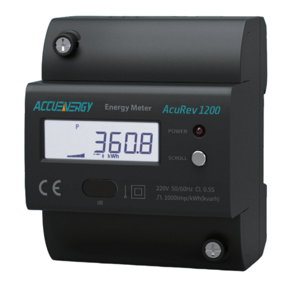
- Page 10 1.1 Meter Overview AcuRev 1200 series rail-mounted three phase energy meter has a small size and high accuracy, and has access to 80A current directly. It is ideal for use in distributor and tight spaces. The meter is equipped with an easy to read liquid crystal display (LCD) which displays all the important informations.
- Page 11 Smart building system Energy management system Industrial environment Energy saving system 1.3 Product Features Multifunction, High accuracy AcuRev 1200 series meter has data collection and management function, energy measurement and multi-parameters measurement function, and demand measurement, event logging, trend record function.
- Page 12 The measurement accuracy of energy, power, voltage, current is 0.5%. Small size, Convenient installation AcuRev 1200 series products' appearance and dimension comply with the IEC 35mm DIN standard, accounts for only 4 mold. Intuitive Display The LCD display is very clear. All measurement parameters could be searched easily through the display .
- Page 14 Before Installtion The installation must be perfomred by qualified, competent accredited professionals who have received formal training and have experience with high voltage and current devices. Appropriate safety wear (gloves, glasses, arc flush suit, etc.) is mandatory to ensure safe installation. ...
- Page 15 This chapter mainly described how to install an AcuRev 1200 series meter, which is a very important step of using the meter correctly. This chapter gives some pictures about how to install the meter and some notes. Before installing the meter, please read this first.
- Page 16 2.2 Installation Methods Note Environmental Before installation, please check the temperature and Temperature and humidity humidity to ensure the AcuRev 1200 series meter is being placed of the environment must accord with the where it will not be damaged. requirement of Acurev 1200, Otherwise it may 1.
- Page 17 2. Humidity 5% to 95% non-condensing. 3. Location AcuRev1200 series meter should be installed in a dry and dust free environment. Avoid exposing meter to excessive heat, radiation and high electrical noise sources. Installation Steps: This meter is DIN rail mounted, which fits 35 mm standard rails. 1.
- Page 18 2. Use the metal clips to tighten the rail and installation will be completed. Figure 2-4 Step B 2.3 Wiring Terminals: R1 R2 P1 P2 Figure 2-5 Meter base terminals Upper row: Current Input, Serial Communication Lower row: Current Output, Digital Output, Relay Output...
- Page 19 Wiring: Figure 2-6 wiring Communication: AcuRev1200 communication utilizes RS485 port, via Modbus-RTU protocol. The wiringterminals are A, B, S. "A" is called differential signal"+", "B" is called differentialsignal"-", "S" is connected to the cupper net of the Shielded Twisted Pair(STP) in the shielding layer. The maximum distance of STP is 1200m.
- Page 20 4. "T" type connection topology should be avoided. This means no new branches except from the starting point. 5. Keep communication cables away as much as possible from sources of electrical noise. When several devices are connected (daisy chain) to the same long communication line, an anti-signal reflecting resistor (typical value 120-300 ohm, 0.25W) is often used at the end of the circuit (the last meter of the chain) if the communication quality is distorted.
- Page 21 Chapter 3 Operation and Application 3.1 Display Panel and Keys 3.2 Display Mode and Key Operations 3.3 Parameter Display and Key Operations 3.4 Settings and Operations...
- Page 22 In this chapter, you would see some details about human-computer interaction, including how to use the keys to research demanded information, and how to set the parameters correctly. 3.1 Display Panel and Keys Chapter 2.1 shows the appearance of Display Module. It consists of one LCD screen and one key.
- Page 23 Four-quadrant reactive energy To indicate the first to forth quadrant reactive energy display Input icon on: display the Consumed Energy Output icon on: display the Generated Energy Inductance icon on: inductive load Load character indicate Capacitor icon on: capacitive load unit Unit of the parameter in parameter display area 3.2 Display Mode and Key Operations...
- Page 24 Note: Configuration 1: Setting corresponding flag to 1 through communication, the consequence would be added to the important parameter display area to cycle display, and the corresponding flag would be cleared and expelled from important parameters. System default display data content cannot be deleted. Configuration 2: Add or delete the corresponding number through pressing keys.
- Page 25 Model Model Model Model Page Setting flag Content Optional display flag word 1 Consumed real energy √ √ √ √ - Bit3 Optional display flag word 1 Consumed real energy tariff 19-22 √ √ - Bit4 Optional display flag word 1 Generated real energy √...
- Page 26 Model Model Model Model Page Setting flag Content Optional display flag word 2 System apparent power √ √ - Bit3 Optional display flag word 2 System power factor √ √ - Bit4 Optional display flag word2 Frequency √ √ √ - Bit5 Optional display flag word2 Real Power demand...
- Page 27 Table 3-3 ModBus RTU protocol data coding table Display Content Specification 1 Specification 2 Specification 3 Specification 4 Meter address Meter address S-01 S-01 S-01 S-01 Baud rate S-02 S-02 S-02 RS485 communication Check mode S-03 S-03 S-03 Energy pulse Energy pulse value S-04 S-04...
- Page 28 Keys presentation: 1. Seal key: Used as electronic seal function. 2. Set key(SET): Used as LCD parameter setting. Short time press (Set) ( the press time is shorter than 2 second) Used to enter the setting mode, enable setting, identify the setting. 3.
- Page 29 authentication Backlight description: If there’s any pressing action, the backlight would be lighten. After no action for 90s, the backlight is off. 3.3 All Parameter Display and Key Operations In the all parameter display mode, short time press the “SCOLL” key to display different parameters.
- Page 30 A) Password protection inquiry Password protection inquiry is the secret key of key setting function. Only if entered the correct password, can you enter the parameter setting page. If users entered wrong password, it would quit the setting mode and enter the important parameter display mode. The factory default password is 0000 Enter the password key operation: Short press “SCOLL”...
- Page 31 “Set” key could change the cursor's blinking state, cursor’s movement,and confirm the setting data( which is changing from cursor blinking state to no cursor blinking state.). Illegal number could not be set and the data would not change. Different specifications support different setting data. Take AcuRev 1203 for example.
- Page 32 Choose Choose...
- Page 33 Chapter 4 Functions and Software 4.1 Parameter Settings 4.2 Basic Measurement Functions 4.3 Energy 4.4 Demand 4.5 RO function 4.6 Event Logging 4.7 Meter Information 4.8 Seal Function...
- Page 34 Take AcuRev 1203 for example. 4.1 Parameter settings AcuRev 1200 series meters need basic settings so that the meters can work in the scheduled way. The figure below is the display of basic parameters that set by PC tools...
- Page 35 Figure 4-1 Basic setting parameters in the software...
- Page 36 1) Reactive power formula True reactive: − − Generalized reactive: − 2) Energy pulse generated Used to choose the pulse type that represented by the pulse generated through P1,P2 terminals. Real: P1,P2 terminals generated pulse is real energy pulse. Reactive: The generated pulse is reactive energy pulse. 3) Demand Demand supports 4 kinds of calculate methods, which are sliding block method, fixed block method, rolling block and thermal demand method.
- Page 37 of the thermal demand table. Set 1-30min as a calculate cycle. In the whole cycle, we just need to calculate the demand once,which means the demand update time is equal to the demand calculate cycle. In this method, in the operation state demand calculation method is displayed to block.
- Page 38 Figure 4-2 Basic Measurement Parameter Display 4.3 Energy AcuRev 1200 series meters provide time of use double direction real-time energy. The boundaries of time could be any day during the date 1-28. Real–time energy can change the energy base. The value only can be changed under the high authority and sealing open condition.
- Page 39 Figure 4-3 Calculation and Measurement Parameter Display Supports time of use energy. According to the demand of users, we can depart the time to several sequence time segments. Each segment can point to the same or different tariff (at most 4 kinds of tariff ).
- Page 40 Figure 4-4 TOU Energy Setting Display a) The current rate of value from the internal clock TOU energy time segment setting: At most 14 time blocks.Each block corresponds with one segment table (at most 8 time segment tables). Each segment can point to anyone of the 4 tariffs.
- Page 41 Time setting demands: 1. Season setting parameter: The calendar year will be divided up into different seasons depending on the season setting parameter. The parameter can be selected from any integer between 1 to 14. User must enter the correct value for the season setting parameter in accordance to the TOU season table.
- Page 42 disabled). 5. Tariff setting parameter: This parameter corresponds to the number of tariffs available for the TOU calendar and can be selected from any integer from 1 to 4. The four tariffs: sharp, peak, valley and normal are represented by 4 integers: 1,2,3 and 4 respectively.
- Page 43 accumulate under the tariff that corresponds to the schedule. b) The value of the currentrate of self-communication order. 8. Daylight saving time (DST): Daylight saving time can be enabled in one of two formats: The fixed date option, or a fixed day of one of the weeks in the month (also named as the non-fixed date option).
- Page 44 Figure 4-5 Daylight Saving Time Setting Display 4.4 Demand Demand have four calculation methods: Sliding block method, fixed block method, rolling block method, thermal demand method. Users can clear the demand.
- Page 45 Figure 4-6 Demand Parameter Display 4.5 RO function AcuRev1200 have relay output (RO), all the way to realize the remote control.
- Page 46 4.6 Event Logging The meter supports the event logging of important operations. Including programming event, open meter cover event, demand clearance event, event clearance event, meter clearance event. Programming event: Record the programming time and programming event flag when programming some important parameters of the meter. When one programming event occur several times within 5 min, the meter just record the first time.
- Page 47 open meter cover event, programming event, support 3 groups of open meter cover event. Support 3 groups of event clearance event. Meter clearance event: Clear parameter record, this event cannot be cleared. Support 3 groups of meter clearance logging. Figure 4-7 Event Clearance Record Display...
- Page 48 4.7 Meter Information Meter type, hardware version, software version, release date, serial number and other basic information as well as the meter running word and real-time clock are available through the meter’s information interface. Figure 4-8 Meter Information Display 4.8 Seal function AcuRev1200 series meters support seal function.
- Page 49 From 107H, we can see if the seal state is valid. When the sealing key is invalid, the address displays open seal state. When the seal is valid the address displays (both 2 seal keys are valid), seal state, and the corresponding content would be shield. Bit0: TOU setting sealing or not Other bits are reserved 20FH...
- Page 50 Modbus address (HEX) Parameter description Communication 908H-909H Total Real Energy tariff 4 √ 90AH-90BH Net Real Energy √ 90CH-90DH Net Real Energy tariff 1 √ 90EH-90FH Net Real Energy tariff 2 √ 910H-911H Net Real Energy tariff 3 √ 912H-913H Net Real Energy tariff 4 √...
- Page 51 Modbus address (HEX) Parameter description Communication 948H-949H Generated Reactive Energy tariff 1 √ 94AH-94BH Generated Reactive Energy tariff 2 √ 94CH-94DH Generated Reactive Energy tariff 3 √ 94EH-94FH Generated Reactive Energy tariff 4 √ 950H-951H Apparent Energy √ Sealing nonstandard content test 1) When the TOU related is valid, the TOU related content need to be shield: Address Parameter...
- Page 53 Chapter 5 Communication 5.1 Modbus Protocol Introduction 5.2 Communication Format 5.3 Application Details...
- Page 54 This chapter introduced how to use software to manipulate the meter through the communication interface. The chapter’s contents include MODBUS protocol, communication format, application details of AcuRev 1200 series meter. 5.1 Modbus Protocol Introduction 1. Transmission mode The mode of transmission defines the data structure within a frame and the rules used to transmit data.
- Page 55 2.1 Frame Format Table 5-1 Data Frame Format Address Function Data Check 8-Bits 8-Bits N x 8-Bits 16-Bits 2.2 Address Field The address field is at the start of the frame. It is composed of 1 byte (8 bits), its decimal value range is 0-247.
- Page 56 2.5 Error Check Field The field allows the error check by master and slave devices. Due to electrical noise and other interferences, a group of data may be changed while transmitting from one location to the another. Error Check ensures master or slave devices do not respond to the distorted data during the transmission, which enhances the system security and efficiency.
- Page 57 of the register, after all the bytes of the message have been applied, is the CRC value. When the CRC is appended to the message, the low-order byte is appended first, followed by the high-order byte. 5.2 Communication Format Table 5-3 Protocol IIIustration Data start Data start Data #of regs...
- Page 58 17 slave device. The data type of energy is dward. Each parameter takes 2 bits, and each bit takes 2 bytes. AcuRev 1200 series meters’ total real energy addresses are 900H, 901H. Total real energy tariff 1 addresses are 902H, 903H.
- Page 59 2. Preset/Reset Multi-Register (Function Code 10H) Set: Function code 10H allows users to change multiple registers’ content, including system parameter,TOU parameter, initialization energy. Table 5-6 is an example of It's Total Real Energy is 0.20KWh,Total Real Energy tariff 1 is 0.12KWh,Total Real Energy tariff 2 is 0.08KWh 17th slave device.
- Page 60 The response data frames: Response data frames, respond to the host data from the machine frame. Include address, function code, the amount of data from the machine and CRC error checking, and packet in each relay occupy a (1 = ON, 0 = OFF), the first byte of the lowest for addressing to relay value, the rest in the back.As shown in table 5-5 for instance relay output state response.
- Page 61 Table 5-9 Independent Control Relay Query DO addr DO addr Value Value CRC16 CRC16 Addr The response data frames: Is a normal response to this command request after the relay state changes back to receive data. Table 5-10 Independent Relay Control Response Response DO addr DO addr Value...
- Page 62 "float"is single precision floating point, using two register addresses.The data range is -0.0~3.402823E+38. 2. The relationship between communication value and real value The meter's communication value does not always equal to the real value. There is a conversion relationship between them. It is very important to be aware of the parameter relationship when users design a communication software, otherwise the result may be incorrect.
- Page 63 Table 5-12 Meter Running State Display Modbus Data Default Register Parameter description Data range Model address(HEX) type value number 1, 2 100H Meter running state word1 Word See table 5-13~5-16 3, 4 1, 2 101H Meter running state word2 Word See table 5-13~5-16 3, 4 1, 2...
- Page 64 Meter running state word 2: Table 5-14 Meter running state word 2 Bit7 Bit6 Bit5 Bit4 Bit3 Bit2 Bit1 Bit0 Reserved Reserved Reserved Reserved Reserved Reserved Reserved Reserved Bit15 Bit14 Bit13 Bit12 Bit11 Bit10 Bit9 Bit8 Reserved Reserved Reserved Reserved Reserved Reserved Reserved Reserved...
- Page 65 Table 5-17 System Parameters address table Modbus Parameter Data Default Register Data range Model address(HEX) description type value number 200H Meter address Word R/W 1-247 1,2,3,4 0x00: On the side 201H Line-side choice Word line; 0xAA: The lower 1,2,3,4 side of the line 202H Reserved 1200...
- Page 66 Modbus Parameter Data Default Register Data range Model address(HEX) description type value number 0: True reactive Reactive power 20DH Word 1:Generalized 3, 4 alculate way reactive 0: IEC 20EH VAR/PF Word 3, 4 1: IEEE Bit0:TOU set 20FH Seal option Word 1:Enable 3, 4...
- Page 67 Modbus Parameter Data Default Register Data range Model address(HEX) description type value number Bit0:Clear demand data Bit1:Clear energy data Bit2:Clear program record B i t 3 : C l e a r o p e n 1, 2 213H Clear meter’s data Word cover record 3, 4...
- Page 68 Screen Set flag Content Type 1 Type 2 Type 3 Type 4 Optional display flag Net active energy √ √ √ √ word1 - Bit1 Optional display flag 14-17 Net active energy rate 1-4 √ √ word1 - Bit2 Optional display flag Consumed Rea energy √...
- Page 69 Screen Set flag Content Type 1 Type 2 Type 3 Type 4 Optional display flag System reactive power √ √ word2 - Bit2 Optional display flag System apparent power √ √ word2 - Bit3 Optional display flag System power factor √...
- Page 70 Modbus Parameter Register Data type Data range Default Model address(HEX) description number Clock 305H Word 0-59 3, 4 :Second 306H Week Word 0: Sunday 3, 4 1~6 Monday-Saturday Daylight saving time setting (03H:read 10H: write) Table 5-20 Daylight saving time address table Modbus Data Register...
- Page 71 Modbus Data Register Parameter description R/W Data range Default Model address(HEX) type number Format 2 35CH DST start month Word R/W 1~12 3, 4 0: Sunday 35DH DST start week Word 3, 4 1~6 Monday- Saturday 35EH DST start which week Word R/W 1~5 3, 4...
- Page 72 Modbus Data Register Parameter description R/W Data range Default Model address(HEX) type number W e e k e n d f e a t u r e Bit0-bit7weekday 406H Word R/W 3, 4 word 0:Weekend Weekend segment 407H Word R/W 1-8 3, 4 table no.
- Page 73 Modbus Data Register Parameter description R/W Data range Default Model address(HEX) type number 12 time zone start 441H-443H 00-00 00 3, 4 time 13 time zone start 444H-446H 00-00 00 3, 4 time 14 time zone start 447H-449H 00-00 00 3, 4 time day 1...
- Page 74 Modbus Data Register Parameter description R/W Data range Default Model address(HEX) type number day 10 time seg 465H-467H start time and tariff 00:00 00 3, 4 number day 11 time seg 468H-46AH start time and tariff 00:00 00 3, 4 day 12 time seg 46BH-46DH...
- Page 75 Modbus Data Register Parameter description R/W Data range Default Model address(HEX) type number day 1-14 time seg 570H-599H start time and tariff 00:00:00 3, 4 number special date and 59AH-59CH 03-12 01 3, 4 time seg special date and 59DH-59FH 09-10 02 3, 4 time seg...
- Page 76 Rate parameter error information word 1(basic parameter) Table 5-22 Tariff parameter error information word 1 Bit7 Bit6 Bit5 Bit4 Bit3 Bit2 Bit1 Bit0 Weekend Holiday Holiday Season Season Schedule Schedule Rate no. Schedule setting Number Setting Setting Table Setting Tariff Setting error Exceeds...
- Page 77 Modbus Parameter Register Data type Data range Default Model address(HEX) description number 816H-817H I_dema Float 0-80.000 3, 4 818H-81FH Reserved Energy data (03H read; 10H write) Table 5-25 Energy data address Modbus Data Register Parameter description Data range Default Model address(HEX) type number...
- Page 78 Modbus Data Register Parameter description Data range Default Model address(HEX) type number Generated Real Energy 922H-923H Dword R/W 0~+99999999 tariff 2 Generated Real Energy 924H-925H Dword R/W 0~+99999999 tariff 3 Generated Real Energy 926H-927H Dword R/W 0~+99999999 tariff 4 928H-929H Total Reactive Energy Dword R/W 0~+99999999 Total Reactive Energy...
- Page 79 Modbus Data Register Parameter description Data range Default Model address(HEX) type number Generated Reactive 946H-947H Dword 0~+99999999 Energy Generated Reactive 948H-949H Dword 0~+99999999 Energy tariff 1 Generated Reactive 94AH-94BH Dword 0~+99999999 Energy tariff 2 Generated Reactive 94CH-94DH Dword 0~+99999999 Energy tariff 3 Generated Reactive 94EH-94FH Dword...
- Page 80 Modbus Data Register Parameter description Data range Default Model address(HEX) type number Consumed Real power 1605H-1606H Float Xx.xxxx kw Tariff 1 max demand and 1607H-1609H Dword YYMMDDhhmmss occur time Consumed Real power 160AH-160BH Float Xx.xxxx kw Tariff 2 max demand and 160CH-160EH Dword YYMMDDhhmmss...
- Page 81 Modbus Data Register Parameter description Data range Default Model address(HEX) type number Consumed reactive power 163CH-163DH Float Xx.xxxx kvar rate 2 max demand and 163EH-1640H Dword YYMMDDhhmmss occur time Consumed reactive power 1641H-1642H Float Xx.xxxx kvar rate 3 max demand and 1643H-1645H Dword YYMMDDhhmmss...
- Page 82 Event logging (03H:read) Programming record Table 5-27 Programming record address Modbus Parameter Data Register Data range Default Model address(HEX) description type number Total 1A00H-1A01H programming Dword 0-999999 3, 4 time Last time programming record 1A02H-1A04H Occur time Word YYMMDDhhmmss 3, 4 Programming 1A05H Word...
- Page 83 Modbus Parameter Register Data type Data range Default Model address(HEX) description number Last time demand clearance record 1B02H-1B04H Occur time Word YYMMDDhhmmss 3, 4 Last 2 time 1B05H-1B0AH 3, 4 Open cover record Table 5-29 Open cover record address Modbus Parameter Data type Data range...
- Page 84 Modbus Data Register Parameter description Default Model address(HEX) type number 1: Clear the programming records Event clearance data 1D05H Word 2: Clear demand 3, 4 flag records 3: Clear open cover records Last 2 time 1D06H-1D0DH 3, 4 Meter clearance event Table 5-31 Meter clearance address Modbus Parameter...
- Page 85 RO control function(01H read,05H write) RO state read(01H) Table 5-32 RO control function-01H Read Modbus Parameter Register Data type R/W Data range Default Model address(HEX) description number 0000H RO state word 1:ON 0:OFF RO control(05H) Table 5-33 RO control function-05H Write Modbus Parameter Register...
- Page 87 Appendix Appendix A Function List Appendix B Technical Data and Specification Appendix C Ordering Information Appendix D Revision History...
- Page 88 Appendix A Function List AcuRev AcuRev AcuRev AcuRev Function Parameter 1201 1202 1203 1204 Real Power Ep_imp, Ep_exp ● ● ● ● Reactive Power Eq_imp, Eq_exp ● ● Energy Apparent Es_imp, Es_exp ● ● Power 4 Tariffs ● ● Power Demand Dmd_P, Dmd_Q, Dmd_S ●...
- Page 89 Appendix B Technical Data and Specification Voltage Standard reference voltageVn 220 Vac l-N Working voltage range 80%-120% Vn Working frequency 50/60Hz Current 10(50)A , 20(80)A Standard reference current In Start current 0.001In Power supply Supply voltage From the voltage loop Consumption <2W or <10VA Environment...
- Page 90 Communication RS485 interface rate 1200-38400bps Communication protocol Modbus-RTU IR interface Non- contact infrared IR interface rate 1200bps Measurement Parameter Accuracy Resolution Range Real energy 0.5% 0.1kWh 0-999999.9 Reactive energy 0.5% 0.1kvar 0-999999.9 Apparent energy 0.5% 0.1kVAh 0-999999.9 Voltage 0.5% 0.1V 175.0V-265.0V Current 0.5%...
- Page 91 Appendix C Ordering Information AcuRev1200 RO protocol 1RO: Limit AcuRev1202/ 1203/1204 optional Communication protocol ModBus: RS485, ModBus-RTU Reference l1: 10 (50)A current l2: 20 (80)A AcuRev 1201 AcuRev 1202 Model AcuRev 1203 AcuRev 1204 For example: AcuRev1203-A1-ModBus-1RO...
- Page 92 Appendix D Revision History Version Date Description V2.01 20141021 First version V2.02 20151211 Increase RO Function Description...
- Page 94 Your Power and Automation Partner! Accuenergy Corporation Toronto - Los Angeles - Beijing North American Toll Free: 1-877-721-8908 Email: support@accuenergy.com Web: www.accuenergy.com...
Need help?
Do you have a question about the AcuRev 1200 Series and is the answer not in the manual?
Questions and answers