Table of Contents
Advertisement
Quick Links
Advertisement
Table of Contents

Subscribe to Our Youtube Channel
Related Manuals for AccuEnergy AcuRev 1312


Summary of Contents for AccuEnergy AcuRev 1312
- Page 1 AcuRev 1312 DIN-Rail Power Meter User's Manual...
- Page 2 The information contained in this document is believed to be accurate at the time of publica- tion, however, Accuenergy assumes no responsibility for any errors which may appear here and reserves the right to make changes without notice. Please ask the local representative for latest product specifications before ordering.
- Page 3 Accuenergy shall not be responsible or liable for any injuries caused by improper meter installation and/or operation.
-
Page 4: Table Of Contents
4.3 Introduction to AcuRev 1310 Utility Software……………………………………………30 4.3.1 Real-time Readings……………………………………………………………………31 4.3.2 Energy Readings………………………………………………………………………32 4.3.3 Device Information……………………………………………………………………33 4.3.4 Settings…………………………………………………………………………………33 4.3.5 Setting the Pulse Output:……………………………………………………………35 Chapter 5: Communication……………………………………36 5.1 Modbus Protocol Introduction……………………………………………………………37 5.2 Communication Format……………………………………………………………………38 5.3 Application Details…………………………………………………………………………40 Appendix…………………………………………………………………45 V: 1.0 Revised: Aug. 2017 www.accuenergy.com... - Page 5 Chapter 2 provides an overview of installation and wiring methods for the AcuRev 1312. Chapter 3 introduces the operation of the AcuRev 1312 via the display panel and how to use the meter to view measurement data and parameter settings.
-
Page 6: Chapter 1: Introduction
AcuRev 1312 DIN-Rail Power Meter Chapter 1: Introduction 1.1 Meter Overview 1.2 Areas of Application 1.3 Product Features... - Page 7 Active, Reactive and Apparent Power. It provides demand forecasting as well as the peak demand. Pulse Output The AcuRev 1312 supports the energy Pulse Output function to output digital pulses. There is a dedicated channel that is KZ output type to transmit pulses proportional to the metered active energy.
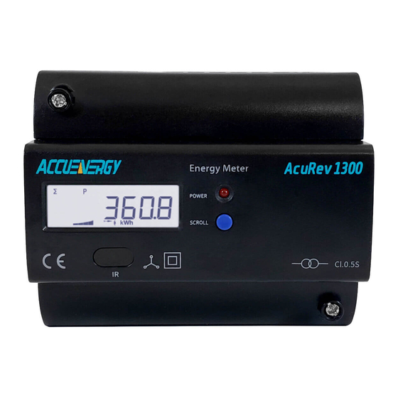
- Page 8 The AcuRev 1312 includes a built-in display to provide clear visibility in all environments. The LCD display of the AcuRev 1312 includes a backlight to aid in visibility when the meter is in- stalled in poor lighting. All the measurement parameters can be easily accessed through the display.
-
Page 9: Chapter 2: Installation
AcuRev 1312 DIN-Rail Power Meter Chapter 2: Installation 2.1 Appearance and Dimensions 2.2 Installation Methods 2.3 Wiring... - Page 10 ⚫ Do not input voltage above the rated specifi cation of the AcuRev 1312 and the devices connected to it. Before energizing the meter, please refer to the meter’s label and specifi ca- tions.
-
Page 11: Appearance And Dimensions
AcuRev 1312 DIN-Rail Power Meter 2.1 Appearance and Dimensions Figure 2.1.1 Unit: mm 108.0 15.0 17.5 62.5 Front View Side View Figure 2.1.2 Front and side views of the AcuRev 1312 V: 1.0 Revised: Aug. 2017 www.accuenergy.com... -
Page 12: Installation Methods
Humidity 5% to 95% non-condensing. Location The AcuRev 1312 should be installed in a dry and dust free environment. Avoid exposing meter to excessive heat, radiation and high electrical noise sources. Installation Steps: This product is DIN railed mounted and fits on a standard 35 mm rail. - Page 13 2. Use the metal clips to tighten onto the rail to complete installation. Figure 2.2.2 2.3 Wiring The terminals of the AcuRev 1312 can be accessed by first removing the terminal covers on the meter. 1. To open the terminal cover, remove the seal if applicable, unscrew the sealing screws and lift the cover upwards to remove.
- Page 14 The steps to attach the top cover is to apply the right side of the cover down into the groove and press down onto the left side. Figure 2.3.2 3. After inserting the cover, tighten the sealing screws and place the seal. Figure 2.3.3 V: 1.0 Revised: Aug. 2017 www.accuenergy.com...
- Page 15 Relay Output Terminals. Auxiliary Power Supply: The AcuRev 1312 power meter requires an AC supply of 100-415V at 60Hz for operation. In nor- mal operation, the power consumption of the meter is less than 1 Watt so the meter can be powered by either an independent power supply or it can obtained from the circuit under test.
- Page 16 The meter requires AWG22-14 as the wires to connect the power supply. Voltage Input: The AcuRev 1312 can measure up to 240V LN/415V LL AC for a three phase system or 400VLN AC for a single phase system. Potential Transformers (PT’s) must be used when the system voltage is higher than the meter’s rated voltage.
- Page 17 AcuRev 1312 DIN-Rail Power Meter The AcuRev 1312 meter supports different wiring configurations for both three phase and single phase systems. Please read this section carefully before choosing a suitable wiring method for your monitoring your system. Here are some of the common installation methods, their respective diagrams and meter con- figurations for the AcuRev 1312 meter.
- Page 18 PTs. The PTs should be connected as shown below. Note: Only two PTs are needed for this connection LINE A B C 1A FUSE Terminal Block V3 V2 V1 AcuRev 1312 LOAD Figure 2.3.7a-2LL wiring diagram using two 5A CT's LINE A B C 1A FUSE Terminal Block...
- Page 19 AcuRev 1312 DIN-Rail Power Meter 3. Single Phase: 2 Lines (Single phase with one line and a neutral) The wiring mode is set to 1LN. One CT needed for this connection. Common Voltage for this connection: 120V LINE 1A FUSE...
- Page 20 The wiring mode is set to 1LL. Two CT's needed for this connection Common Voltage: 120V LN/240V LL LINE A N B 1A FUSE Terminal Block V3 V2 V1 AcuRev 1312 LOAD Figure 2.3.9a-1LL wiring diagram using two 5A CT's LINE A N B 1A FUSE Terminal Block...
- Page 21 DIN-Rail Power Meter Communication The AcuRev 1312 supports Modbus-RTU protocol through it’s built-in RS485 port. The RS485 terminals are denoted as ‘A’, ‘B’ and ‘S’. ‘A’ is the positive diff erential terminal, ‘B’ is the negative diff erential terminal and ‘S’ is for connecting the shield of the shielded twisted pair cable.
-
Page 22: Chapter 3: Operation
AcuRev 1312 DIN-Rail Power Meter Chapter 3: Operation 3.1 Display Panel and Keys 3.2 Display Modand Key Operations... - Page 23 AcuRev 1312 DIN-Rail Power Meter In this chapter, users will be introduced to the interface of the AcuRev 1312 meter as well as how to interact with the meter using the key on the display to read and configure parameters.
-
Page 24: Display Mode And Key Operations
AcuRev 1312 meter. Pressing and holding the “SCROLL” key from the important parameter display mode will direct the user to the all parameter display mode. In this mode there will be a displayed in the bottom row of the display to indicate the AcuRev 1312 is in all parameter display mode. - Page 25 Meter run time Load run time Setting mode: The settings mode is where the user can perform most configurations for the AcuRev 1312. Pressing the “SET” key that is located under the meter cover will prompt the user for the meter password.
- Page 26 3LN; 1LN; 1LL;2LL 5A/1A(5A Current Input) 80mA/100mA (mA Current Input) 1~50,000 50~400 50~1000000 Pulse Constant 1~60000 Pulse Width 20~100ms Energy Decimal places Custom data display: Add Custom data display: Remove Wiring check enable On; Off V: 1.0 Revised: Aug. 2017 www.accuenergy.com...
-
Page 27: Chapter 4: Functions And Software
AcuRev 1312 DIN-Rail Power Meter Chapter 4: Functions and Software 4.1 Confi guration 4.2 Energy Pulse Output 4.3 Introduction to software 4.3.1 Real-Time Readings 4.3.2 Energy Readings 4.3.3 Device Information 4.3.4 Settings 4.3.5 Setting the Pulse Output... -
Page 28: Configuration
4.1 Confi guration The AcuRev 1312 needs to be confi gured correctly in order for it to measure the data correctly. For the initial meter setup, The wire mode, PT and CT ratios needs to be set confi gured. Here are the steps to setup the meter from the display. -
Page 29: Energy Pulse Output
The AcuRev 1312 supports the transmission of pulses through the P1 and P2 terminals of the meter. The AcuRev 1312 uses the KZ output to transmit test pulses that are proportional to the accumulated energy that the meter is measuring. - Page 30 ➂ This means 1 pulse = (1/2200) kWh; therefore 2200 pulses = 1 kWh ➃ Since we get 2200 pulse/kWh, enter 2200 as the pulse constant into the meter ► Press “SCROLL” to get to the “S-14 PH” page. This configuration will represent the pulse V: 1.0 Revised: Aug. 2017 www.accuenergy.com...
-
Page 31: Introduction To Acurev 1310 Utility Software
4.3 Introduction to AcuRev 1310 Utility Software The AcuRev 1312 meter can be accessed through the AcuRev 1310 Utility Software. This soft- ware can be used to read the meters’ measurements or to configure the meters’ configurations. -
Page 32: Real-Time Readings
⚫ Locate the USB Serial Port(COMx) information where x is the port number to use. Select the baud rate and parity of the meter and enter the device address. Click OK to connect the AcuRev 1312 to the software. 4.3.1 Real-time Readings Upon successful connection, users will see readings appear in blue font beside each measure- ment parameter as shown in Figure 4.3.2... -
Page 33: Energy Readings
TOU energy as either the current month, previous month or the past two months. Users can also provide initial values for the AcuRev 1312 to start to accumulate energy from. To do this users must have sufficient permission, which can be obtained from the General Settings page. -
Page 34: Device Information
4.3.4 Settings The settings related to the AcuRev 1312 can be found by clicking on the “Settings” menu. To set up the meter for initial use, the settings can be found from the “General Settings”. Alter- natively, users can click on the icon highlighted below in the black box in Figure 4.3.5. - Page 35 AcuRev 1312 DIN-Rail Power Meter Figure 4.3.5 Users only need to select the “Wiring Method” and fill in the “CT1” field with the rated input of the CT they are using and the “PT1” and “PT2” fields with the PT ratio of the PT they are using.
-
Page 36: Setting The Pulse Output
From the “General Settings” page in the software, users can configure the meter to output puls- es corresponding to the energy that the AcuRev 1312 is measuring. Under “Energy Pulse Output”, the type of energy that will be outputted needs to be selected as either “Real Energy”... -
Page 37: Chapter 5: Communication
AcuRev 1312 DIN-Rail Power Meter Chapter 5: Communication 5.1 Modbus Protocol Introduction 5.2 Communication Format 5.3 Application details... - Page 38 ⚫ Error Checking Frame: When the query to the AcuRev 1312 meter (slave device) is received, the meter removes the frame header and reads the data. If there are no errors, then the meter will implement the data’s task. Once the task is completed, the meter will put its own data with the acquired header and send back the frame to the master device that queried the meter.
-
Page 39: Communication Format
This function code allows the user to obtain the measurement data from the AcuRev 1312. Below is a example of an query for reading three of the AcuRev 1312’s energy parameters. The query is requesting the total active energy, tariff 1 active energy and tariff 2 active energy from the meter with device address of 17. - Page 40 Response: The AcuRev 1312 responds back to the master’s query by responding with its slave device, func- tion code, data and CRC check. Below is the response from the AcuRev 1312 for returning the total active energy (1.27kWh), tariff 1 energy (1.00kWh) and tariff 2 energy(0.27kWh).
-
Page 41: Application Details
2.Relationship between communication value and real value. The measurement values from the AcuRev 1312 meter obtained through Modbus may not al- ways be equal to the real value. The values may be scaled or a relationship may need to be ap- plied. - Page 42 Chapter 5: Communication 3. Parameter Address Table For the complete Modbus addresses that the AcuRev 1312 supports, please reference the AcuRev 1310 Series User Manual. System Parameter Settings: Function Code: 03H to Read; 10H to Write Modbus Address Data P r o p -...
- Page 43 AcuRev 1312 DIN-Rail Power Meter Modbus Address Data P r o p - #of reg- Parameter Range Default Decimal Type erty isters 219H Pulse Width word R/W 20-100 ms Energy display 21AH word R/W 0,1, 2, 3 Decimal Clock Parameters: Function Code: 03H to Read; 10H to Write...
- Page 44 Total Apparent Energy: 2064H-2065H 8292-8293 Dword R/W 0-999999999 VAh Phase C Total Reactive Energy 2066H-2067H 8294-8295 Dword R/W 0-999999999 varh Consumed: Q1 Total Reactive Energy 2068H-2069H 8296-8297 Consumed: Q1 Phase Dword R/W 0-999999999 varh V: 1.0 Revised: Aug. 2017 www.accuenergy.com...
- Page 45 AcuRev 1312 DIN-Rail Power Meter Modbus Address Data Prop- #of reg- Parameter Range Type erty fault isters Decimal Total Reactive Energy 206AH-206BH 8298-8299 Consumed: Q1 Phase Dword R/W 0-999999999 varh Total Reactive Energy 206CH-206DH 8300-8301 Consumed: Q1 Phase Dword R/W...
-
Page 46: Appendix
AcuRev 1312 DIN-Rail Power Meter Appendix... -
Page 47: Specifications
AcuRev 1312 DIN-Rail Power Meter METERING Parameter Accuracy Resolution Range Active energy 0.5% 0-999999999 Reactive energy 0.5% 1varh 0-999999999 Apparent energy 0.5% 1VAh 0-999999999 Voltage 0.5% 0.1V 10V-1000KV Current 0.5% 0.001A 10mA-500000A Active power 0.5% -99-99MW Reactive power 0.5% 1var... - Page 48 MAKE ENERGY USAGE SMARTER ACCUENERGY (CANADA) INC. TF: 1-877-721-8908 INT: +1-416-497-4100 2 Lansing Square, Suite 700 FAX: +1-416-497-4130 Toronto, ON M2J 4P8, Canada E: marketing@accuenergy.com...
Need help?
Do you have a question about the AcuRev 1312 and is the answer not in the manual?
Questions and answers