Table of Contents
Advertisement
Advertisement
Table of Contents

Related Manuals for AccuEnergy Acuvim-L Series


Summary of Contents for AccuEnergy Acuvim-L Series
- Page 2 The information contained in this document is believed to be accurate at the time of publication, however, Accuenergy assumes no responsibility for any errors which may appear here and reserves the right to make changes without notice. Please ask the local representative for latest product specifications before ordering.
- Page 3 Please read this manual carefully before installation, operation and maintenance of Acuvim-L power meter. The following symbols in this manual and on Acuvim-L series meters are used to provide warning of danger or risk during the installation and operation of the meters.
-
Page 4: Table Of Contents
Content Chapter 1 Introduction-------------------------------------------------------------------1 1.1 Functionality ---------------------------------------------------------------2 1.2 Areas of application -------------------------------------------------------------2 1.3 Meter overview--------------------------------------------------------------3 Chapter 2 Installation---------------------------------------------------------------------7 2.1 Appearance and dimensions---------------------------------------------9 2.2 Installation Method-------------------------------------------------------------12 2.3 Wiring -------------------------------------------------------------------------------15 Chapter 3 Meter Operation and Parameter Setting-------------------------------31 3.1 Display Panel and Keys------------------------------------------------32 3.2 Metering Data Reading--------------------------------------------------34 3.3 Statistics Display-------------------------------------------------------------42 3.4 System Parameter Setting -----------------------------------------------------47... - Page 5 4.5 Data address table------------------------------------------------------------134 Appendix A Technical data and Specification-----------------------------------------------178 Appendix B Ordering Information-------------------------------------------------------------182 Appendix C Revision History---------------------------------------------------------------------184...
- Page 6 5. Additional documentation (Quick Setup Guide, Calibration Certificate) To avoid complications, please read this manual carefully before installation and operation of the Acuvim-L series meter. Chapter 1 Chapter 1 Introduction. Chapter 2 Installation and Wiring. Chapter 3 Meter Display and Parameter Settings.
-
Page 7: Chapter 1 Introduction
Chapter 1 Introduction 1.1 Functionality 1.2 Areas of Application 1.3 Meter Overview... - Page 8 Compact and Easy to Install Acuvim-L series meter can be installed into a standard ANSI C39.1 (4" round) or an IEC 92mm DIN (square) slot. With the 51mm depth , the meter can be installed in a small cabin. Installation clips are used for easy installation and removal.
-
Page 9: Meter Overview
Acuvim-L series meter is the ideal choice for replacing traditional, analog electric meters. It uses true RMS measuring methods so that nonlinear load can be monitored. Except providing means of monitoring and measuring power distribution automation system, it can also be used as a remote terminal unit (RTU) for monitoring and controlling a SCADA system. - Page 10 Function Parameters Energy Ep_imp, Ep_exp Reactive Energy Eq_imp, Eq_exp Energy Apparent Energy Current Dmd_I1, Dmd_I2, Demand Dmd_I3 Demand Dmd_Psum, Dmd_ Power Demand...
- Page 11 Dmd_I1_max, Max Current Dmd_I2 _max, Demand Dmd_I3_max Dmd_Psum_max, Max Power Dmd_Qsum_max, Demand Statistics Dmd_Ssum_max Max/Min Umax, Umin Voltage Max/Min Imax, Imin ...
-
Page 12: Chapter 2 Installation
Chapter 2 Installation 2.1 Appearance and Dimensions 2.2 Installation Methods 2.3 Wiring... -
Page 13: Considerations When Installing Meters
Considerations When Installing Meters Installation of the meter must be performed by qualified personnel only, who follow standard safety precautions through the installation procedures. Those personnel should have appropriate training and experience with high voltage devices. Appropriate safety gloves, safety glasses and protective clothing are recommended. - Page 14 The installation method is introduced in the chapter. Please read this chapter carefully before beginning installation . 2.1 Appearance and Dimensions Units: mm(inches) Multifunction Power Meter Gasket 96.00 (3.800) Gasket Front View of the Display Meter and Remote Display Unit 7.60 (0.300) ...
- Page 15 Front Casing mounting onto a panel. Key Four keys are used to select display and set. The Acuvim-L series meter enclosures is made Enclosure of high strength anti-combustible engineering plastic. Used for Installation 35mm rail of the DIN rail ...
- Page 16 IO module appearance and mechanical dimensions 19 .5 mm Fig.2-2 structure configuration of IO modules PROFIBUS module and Ethernet module appearance and mechanical dimensions 90.00 22.00 Fig.2-3 structure configuration of PROFIBUS modules...
- Page 17 Installation steps Acuvim-L series meter can be installed into a standard ANSI C39.1 (4” round) or an IEC 92mm DIN (square) form. 1. Cut a square or round hole on the panel of the switch gear. The cutting size shows as Fig.2-4.
- Page 18 2. Remove the clips from the meter and put Acuvim-L into the square hole from the front side. Panel Panel Fig.2-5 Put the meter into the square 3. Install the clips to the meter from backside and push the clips tightly so that the meter is fixed on the panel.
- Page 19 Module Installation (1) The extend module could be installed from the bottom of the meter . (2) The extend module is fixed on the meter by the screw. (3) Please install the PROFIBUS module first if both IO and PROFIBUS module are selected.
-
Page 20: Wiring
2.3 Wiring 2.3.1 Terminal Strips There are three or four terminal strips at the back of the Acuvim-L series meter depending on different models. The terminal strip diagrams are shown in below. The three phase voltage and current are represented by using 1, 2, and 3 respectively. - Page 21 Communication terminal strips Digital output terminal strips ALUM0213 ALUM0212 16 15 14 16 15 14 DOC DO2 DO1 Digital Output Comm Port Fig.2-8 Terminal diagram of Acuvim-L Note: Acuvim-AL does not have digital output and commnication terminal strips Acuvim-BL has digital output terminal strip Acuvim-CL/DL/EL/KL have communication terminal strip Comm Port Digital Input...
- Page 22 Note There are two Auxiliary Power Supply options for the Make sure the power Acuvim-L series meter: s u p p l y v o l t a g e i s 1. Standard: 100~415Vac (50/60Hz) or 100~300Vdc within the required 2.
- Page 23 Fig.2-12 wiring connection of auxiliary power supply with EMC filters Voltage input Maximum input voltage for the Acuvim-L series meter shall not exceed 400LN/690LL VAC rms for three phase or 400LN VAC rms for single phase. Potential Transformer (PT) must be used for high voltage systems. Typical secondary output for PTs shall be less than or equal to 400V.
- Page 24 details). CTs must be used if the system rated current is over 5A. The accuracy of the CT should be better than 0.5% with rating over 3VA is recommended in order to preserve the meter’s accuracy. The wire between CTs and the meter shall be as short as possible.
- Page 25 2.3.3 Voltage Input Wiring 3-Phase 4-Line Wye mode (3LN) The 3-Phase 4-Line Wye mode is popularly used in low voltage electric distribution power system. For voltage lower than 400LN/690LL Vac, power line can be connected directly to the meter’s voltage input port as shown in Fig.2- 13a.
- Page 26 3-Phase 3-Line direct connection mode (3LL) In a 3-Phase 3-Line system, power line A, B and C are connected to V1, V2 and V3 directly. Vn is floated. The voltage input mode of the meter should be set to 3LL. LINE 1A FUSE Acuvim-L...
- Page 27 2.3.4 Current Input Wiring The 3CT current wiring configuration can be used when either 3CTs are connected (as shown in Fig.2-16) or 2CTs are connected (as shown in Fig.2-17) to the system. In either case, there is current flowing through all three current terminals.
- Page 28 The difference between Fig.2-17 and Fig.2-18 is that no current flows through current input terminal I21 and I22. The I2 value is calculated from formula i1+i2+i3=0. The current input mode of the meter should be set to 2CT . LINE Terminal block Acuvim-L ALUM0227...
- Page 29 2.3.5 Frequently used wiring method In this section, most common voltage and current wiring connection combinations are put together into different diagrams. In order to display measurement readings correctly, please select the approprate wiring diagram according your setup and application. Note: Acuvim-L supports 3LN-3CT(Using the 3CT and a 2CT two wiring), 3LL-3CT, 2LL-3CT, 2LL-2CT, 1LL-2CT and 1LN-1CT.
- Page 30 2. 3LN, 3CT with 2 CTs (Wiring mode: 3LN,3CT) LINE 1A FUSE Terminal block Acuvim-L ALUM0230 LOAD Fig.2-21 3LN, 3CT with 2CTs 3. 3LL,3CT(Wiring mode:3LL,3CT) LINE 1A FUSE Terminal block V3 V2 V1 Acuvim-L LOAD ALUM0231 Fig.2-22 3LL, 3CT...
- Page 31 4. 2LL, 3CT (Wiring mode: 2LL, 3CT) LINE 1A FUSE Terminal block Acuvim-L ALUM0232 LOAD Fig.2-23 2LL, 3CT 5. 2LL, 2CT (Wiring mode: 2LL, 2CT) LINE 1A FUSE Terminal block Acuvim-L ALUM0233 LOAD Fig.2-24 2LL, 2CT...
- Page 32 6.1LN, 1CT(Wiring mode:1LN, 1CT) LINE 1A FUSE Terminal block Acuvim-L ALUM0234 LOAD Fig.2-25 1LN,1CT 7. 1LL, 2CT(Wiring mode:1LL, 2CT) LINE 1A FUSE Terminal block Acuvim- ALUM0235 LOAD Fig.2-26 1LL,2CT Note: For the 1LL, 2CT, A and B facies of the phase Angle is 180...
- Page 33 2.3.6 Digital Output (DO) There are two digital outputs for Acuvim-L. For the Acuvim-BL, the terminals of the digital output are DO1 , DO2 and DOC . For the Acuvim-DL/EL, the terminals of the digital output respectively is DO11, DO12 and DO21, DO22.These two digital outputs can be used as energy pulse output or over/under limit alarming output.
- Page 34 AWG22 (0.5mm2) or larger. The overall length of the RS485 cable connecting all devices can not exceed 1200m (4000ft). Acuvim-L series meter can be used as a slave device of a master device such as PC, PLC, Data Collector and RTU.
- Page 35 All meter have been standardized. In order to improve the quality of communications, now offers the following Suggestions: The shield of the RS485 cable must be connected to the ground at one end only. Every A(+) should be connected to A(+), B(-) to B(-), or it will influence the network, even damage the communication interface.
-
Page 36: Chapter 3 Meter Operation And Parameter Setting
Chapter 3 Meter Operation and Parameter Setting 3.1 Display Panel and Keys 3.2 Metering Data 3.3 Statistics Display 3.4 System Parameter Setting 3.5 DO Parameter Setting and Expansion Module Setting 3.6 Ethernet Network Module Settings 3.7 DI Status Display 3.8 TOU Energy and Maximum Demand Display 3.9 Measurement Methods and Parameters Definitations... -
Page 37: Display Panel And Keys
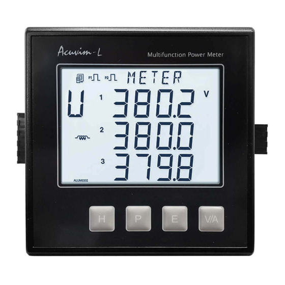
3.1 Display Panel and Keys The front of the Acuvim-L series meter consists of an LCD screen and four control keys. All display segments are shown as Fig.3-1 below: ALUM0301... - Page 38 display Description Display metering data Three lines of " " digits Voltage, current, power, power fac tor, THD, in the metering area frequency, demand, unbalance factor, max, min etc. Display current status Status display area Meter: metering status; Max: maximum value; Min: One line of"...
-
Page 39: Metering Data Reading
3.2 Metering Data Acuvim-L series meter displays the voltage metering screen (default screen) when first powered up. Different key combinations show different screen. Press “V/A” to show real-time metering data; press “E” to show energy parameters; press “P” to show power parameters; press “H” to show power quality information; press “H”... - Page 40 Press “V/A” to go to the next screen. The 2 screen: Line to line voltage: U12, U23 and U31. As shown in Fig.3-3, U12=658.5 V, U23=658.0 V, U31=657.8 V. Press “V/A” to go to the next screen. ALUM0303 Fig.3-3 Three phase voltage The 3 screen: Current for each phase: I1, I2 and I3.
- Page 41 The 5 screen: Current demand of each phase. As shown in Fig.3-6, Dmd_I1=2.503 A, Dmd_ I2=2.501 A, Dmd_I3=2.500 A. Press “V/A” to go back to the 1st screen. ALUM0306 Fig.3-6 Demand current Note: For Acuvim-KL, only the current page is displayed. When the wiring mode is set to 3LL-3CT,2LL-3CT or 2LL-2CT, it will not display phase voltage and neutral current , there is no the 1 and 4...
- Page 42 The 2 screen: Reactive power of each phase. As shown in Fig.3-8, Q1=0.823 kvar, Q2=0.823 kvar,Q3=0.822 kvar. Press “P”, go to the next screen. ALUM0308 Fig.3-8 Three phase reactive power The 3 screen: Apparent power of each phase. As shown in Fig.3-9, S1=0.950 kVA, S2=0.951 kVA,S3=0.950 kVA.
- Page 43 The 5 screen: Power factor of each phase: PF1,PF2, PF3. As shown in Fig.3-11, PF1=0.500, PF2=0.499, PF3=0.500. Press “P” to go to the next screen. ALUM0310 Fig.3-11 Three phase power factor The 6 screen: System average power factor PF and system frequency F. As shown in Fig.3-12, PF=0.500, F=50.01 Hz.
- Page 44 For other series meters, if the wiring is set to 2LL, or 3LL, there is no single-phase power and single-phase power factor displayed, press P to switch between screens only 4,6,7. The 1 screen: Import energy As shown in Fig. 3-14, Ep_imp=50.9 kWh. Press “E”, go to the next screen.
- Page 45 The 4 screen: Capactive (export) reactive energy. As shown in Fig. 3-17, Eq_exp=1.5 kvarh. Press “E” to go to the next screen. ALUM0316 Fig.3-17 Export reactive energy The 5 screen: Apparent energy. As shown in Fig.3-18, Es = 3.0kVAh. Press “E” to go to the next screen. ALUM0317 Fig.3-18 Apparent energy The 6...
- Page 46 The 7 screen: Load Run hours. As shown in Fig.3-20, Load Run hour = 1.3 hours. Press “E” to go to the next screen. Note: This screen only applies to Acuvim-DL, EL and KL. Note: In real-time metering mode, Acuvim-AL, Fig.3-20 Load Run hours Acuvim-BL, Acuvim-CL,Acuvim-DL and Acuvim-EL display voltage and current THD when “H”...
-
Page 47: Statistics Display
The 2 screen: Phase current THD: THD_I1, THD_ I2, THD_I3. As shown in Fig 3-23, THD of three phase current, THD_I1=1.89%, THD_I2=1.83%, THD_I3=1.85%. Press “H” key, go back to the 1 screen. ALUM0321 Fig.3-23 Current THD Note: When voltage wiring mode is set to 1LN, display only shows phase current THD: THD-I1. - Page 48 MAX=380.2 V, U3_MAX=380.5 V. The 2 screen: MIN value of phase voltage. The “MIN” icon shown on the top of screen. As shown in Fig.3-25, U1_MIN=379.6 V, U2_MIN=379.8 V, U3_MIN=379.7 V. Press “V/A” to go to the next screen. ALUM0323 Fig.3-25 Min value of phase voltage The 3 screen: Max value of line to line voltage.
- Page 49 The 5 screen: MAX value of current. As shown in Fig.3-28, I1_MAX=2.502 A , I2_MAX=2.503 A, I3_MAX=2.502 A . Press “V/A” to go to the next screen. ALUM0326 Fig.3-28 Max value of current The 6 screen: MIN value of current. As shown in Fig.3-29, I1_MIN=2.498 A, I2_MIN=2.496 A, I3_MIN=2.497 A.
- Page 50 3.3.2 Display the Max value of power and reactive power demand. Press “P” under the statistics display mode to display the peak value for power, reactive power and apparent power demand. As shown in Fig.3-31, P_Demand_MAX=1.435 kW, Q_Demand_MAX=2.478 kvar, S_Demand_MAX = 2.850 kVA.
- Page 51 The 2 screen: 2 harmonic content of voltage. As shown in Fig.3-33, U1_Hr2=0.12%, U2_Hr2=0.14% , U3_Hr2=0.12%. Press H to scroll through the 3 to the 31 phase voltage harmonic content ALUM0331 Fig.3-33 2 harmonic content of phase Note: When voltage wiring of the meter is set to 2LL voltage or 3LL, line to line voltage harmonic contents will be display instead (as shown in Fig.
-
Page 52: System Parameter Setting
3.4 System Parameter Setting Press “H” and “V/A” simultaneously in the metering data display mode to enter the system parameter setting mode. All the settings can be done through the keys on the meter front panel. Press “H” to move the flashing cursor to the right, press “P” to increase the number by 1 once a time, press “E”... - Page 53 The 1 screen: Communication Address setting. The address can be any integer between 1 - 247. As shown in Fig.3-37, the communication address is 1. To change the address, press “H” to move the cursor, press “P” to increase value by 1, press “E” to decrease value by 1.
- Page 54 Note: The page is only shown in Acuvim-EL and KL. “non1” represents non-parity, single stop bit; “non2” represents non-parity, double stop bit; “odd” represents odd-parity, single stop-bit; “EVEN” represents even parity, single stop bit. By default it is set as “EVEN”. The 4 screen: Voltage input wiring setting.
- Page 55 The 7 screen: PT secondary side ratio setting. PT2 ratio can be set from 50.0 to 400.0 (unit in V). As shown in Fig.3-43, PT2=380.0V. To change PT2 value, press “H” to move the cursor, press “P” to increase value by 1, press “E” ALUM0340 to decrease value by 1.
- Page 56 The 9 screen: CT secondary side ratio setting. CT2 can be 1, 5 and 333; user can modify the CT2 as 1 or 5, if CT2=333mv, it can not be modified. As shown in Fig.3-45, CT1=5A, Press “V/A” to proceed to the next page. ALUM0342 Fig.3-45 CT secondary side ratio setting The 10...
- Page 57 The 12 screen: Sliding windows time for demand setting. Sliding windows time of demand can be set from 1-30 minute. The window slides once per minute. As shown in Fig.3-48, the sliding windows time is ALUM0345 8 minute. Fig.3-48 Sliding windows time for demand setting The 13 screen: Clear Max and Min page setting.
- Page 58 The 15 screen: Acknowledgement to clear energy setting. This screen appears only when the 14 screen is set as “enable”. Press “E” or “P” to select “YES” or “NO”: ALUM0348 “YES”: clear energy; Fig.3-51 Acknowledgement to clear “NO”: do not clear energy. energy setting All energy parameters will be set to 0 when “YES”...
-
Page 59: Do Parameter Setting And Expansion Module Setting
The 18 screen: VAR/PF setting. Press “P” or “E” to change VAR/PF setting. As shown in Fig.3-54 is IEC standard. Note: The page would be show only in Acuvim-EL. Fig.3-54 VAR/PF setting The 19 screen: Password setting. This is the last screen in system parameter setting mode. - Page 60 If the extend IO module could be added, it contains 2 DO, 4 DI and communication with Modbus-RTU standard. Press “P” key and “E” key simutaneously under system parameter setting mode to enter DO parameter setting and Extend IO communication setting mode, the operation about key is same as Acuvim-BL DO setting.The following steps show how to set DO items: The 1 screen: Extend IO baud rate setting.
- Page 61 The 3 screen: DO1 output mode setting. 0: pulse output; 1: alarm output. As shown in Fig.3- 58, DO1 is set as pulse output mode. Press “V/A” to accept change and proceed to the next page. ALUM0351 Fig.3-58 DO1 output mode setting The 4 screen: DO2 output mode setting.
- Page 62 The 6 screen: DO pulse width setting. DO pulse width can be set from any integer from 1 to 50. Each unit stands for 20ms. As shown in Fig.3-61, the pulse width is set to 5, that is 5×20=100ms. ALUM0354 Press “V/A”...
- Page 63 The 9 screen: DO delay time for alarm setting. If alarm condition lasts for over the preset time period, the alarm signal will be triggered. The delay time can be set from any integer from 0 to 255. Each unit stands for 300ms. ALUM0357 Fig.3-64 DO delay time for alarm setting The10...
- Page 64 The 11 screen: DO1 inequality sign setting. 0: < (less than); 1: > (greater than) As shown in Fig.3-66, the inequality sign is set to 1, which means when the tracking value is above the preset limit, an alarm output will be triggered. ALUM0359 Press “V/A”...
- Page 65 The 14 screen: DO2 inequality sign setting. 0: < (less than); 1: > (greater than) Press “V/A” to accept change and proceed to the next page. ALUM0362 Fig.3-69 DO2 inequality sign setting The 15 screen: DO2 alarm limit setting. Set the alarming limit value for the tracking parameter.
-
Page 66: Ethernet Network Module Settings
The 17 screen: PROFIBUS address setting page. PROFIBUS address can be set from 0~126, this page will display if the power meter connect a PROFIBUS module. PROFIBUS address can be set only via key, and it ALUM0365 valid right now after modified. Fig.3-72 PROFIBUS address setting Only Acuvim-DL/EL display the page. - Page 67 The 2 screen: Displays the IP address settings page. IP address: 192.168.3.1 ALUM0367 Fig.3-74 IP address setting The 3 screen: Displays the subnet mask address (SUBMASK) settings page. Such as the subnet mask address is: 255.255.255.0 ALUM0368 Fig.3-75 Subnet mask address etting The 4 screen: Displays the gateway address (Gateway) settings page.
- Page 68 The 5 screen: Displays the IP address of the domain name server (DNS1) settings page. Such as server address 1:202.168.0.1 ALUM0370 Fig.3-77 Domain name server(DNS1) setting The 6 screen: Displays the domain name server address (DNS2) Settings page. Such as server address 2:202.168.0.4 ALUM0371 Fig.3-78 Domain name server(DNS2)
- Page 69 The 8 screen: Displays the HTTP port settings page. HTTP port address is 8080. ALUM0373 Fig.3-80 HTTP port setting The 9 screen: Displays network module reset settings page. Is set to 1, the reset network module; such as 0, is not reset. ALUM0374 Fig.3-81 Network module reset setting The 10...
-
Page 70: Di Status Display
3.7 DI status Display function Acuvim-DL and Acuvim-EL support display of 4 extend DI status. Press “H” + “P”can enter or exit DI status display. The pages can be turned by pressing “V/A”. From Fig. 3-83 to Fig. 3-86, it shows that all of the 4 DIs status are OFF. The 1 screen: DI1 current status display. -
Page 71: Tou Energy And Maximum Demand Display
The 4 screen: DI4 current status display. if DI4 status is turn on, the screen will display “ON”. if DI4 status is turn off, the screen will display “OFF”. As show in Fig.3-86, DI4 ststus is turn off. ALUM0379 Fig.3-86 DI4 status display 3.8 TOU Energy and Maximum Demand Display Press “V/A”... - Page 72 The 2 screen: Total tariff export energy. As shown in Fig.3-88, Ep_ Exp=203.8kWh. Press “V/A” to turn to the next screen. Fig.3-88 Total tariff export energy The 3 screen: Total tariff import reactive energy. As shown in Fig.3-89, Eq_ Imp=3025.8 kvarh.Press “V/A”...
- Page 73 The 5 screen: Total tariff apparent energy of TOU. As shown in Fig.3-91, Es=1879.8 kVAh.Press “V/ A” return to 1st screen, then press “H” turn to 6th screen. In the same way, press “V/A” key to switch the screen under the same tariffs. Fig.3-91 Total tariff apparent energy Press “H”...
- Page 74 Power (P): Three phase power and total system power are measured and displayed in the Acuvim-L series meter. Reactive power (Q): Acuvim-L series meter uses the following two methods for reactive power calculation. 1. Sinusoidal reactive power. The formula is as follows:...
- Page 75 Q: Budeanu’s reactive power. Apparent power (S): Three phase apparent power and total system apparent power are measured and displayed in the Acuvim-L series meter. Power factor (PF): Three phase power factor and total system power factor are measured and displayed in the Acuvim-L series meter.
- Page 76 Export reactive energy (Eq_exp): capacitive energy. Apparent energy: apparent energy is time integral of apparent power. The unit is kVAh. Harmonic parameter (not available for Acuvim-EL): Total harmonic distortion: this factor is often used to express the power quality of the power system. The formula is as follows: ...
- Page 77 Max/Min: Acuvim-L series meter can measure the max value of real system power, reactive power and apparent power and the max/min of the three phase voltage and current. The data is stored in non-volatile memory and can be accessed or cleared via meter front or communication.
- Page 78 schedule can be divided up into 14 segments (in which each segment can have its own tariff ). User can customize the TOU calendar (including its tariffs, seasons, schedules and segments) according to different applications. To make sure that the TOU calendar is setup correctly, the meter will check the TOU settings according to the predefined rules (see below for “TOU setting format requirement”...
- Page 79 3. Schedule setting parameter: The number of available TOU schedules depends on the schedule setting parameter. The parameter can be selected from any integer between 1 to 14. This parameter determines the number of TOU schedules available for the TOU calendar setting. A maximum of 14 TOU schedules (from TOU Schedule #1 to TOU Schedule #14) can be used.
- Page 80 tariffs (sharp and peak) will be available. 7. Holiday setting parameter: This parameter can be set from any integer between 1 and 30, meaning a maximum of 30 holidays can be programmed to the TOU calendar. If the holiday setting parameter is set as 3, the first 3 slots of the holiday schedule must be set, otherwise it will be considered as an invalid input (TOU function will be disabled).
- Page 81 Fig.3-94 DST setting interface...
- Page 82 10.Holidays preset function: Ten years holiday setting In this setting, users can program holidays in the future decade. The format is month / day , holiday code. When “Enable Holiday Years Settings” is checked, users can click “Make Holiday Settings (10 Year)” to enter the holiday table setup page. Once the setup is done, users can click “Generate”, by which a holiday table for the next decade can be generated.
- Page 83 11. Weekend Schedule: Weekend Setting (bit0 : Sunday; bit1 ~ bit6: Monday to Saturday; bit 0 means not effective, bit 1 means effective). For example, when the Weekend Setting bit0 is 1, it means Sunday is effective. When the Weekend Setting bit1 is 1, it means Monday is effective.
- Page 84 function chapter. Energy Pulse Output: The two digital outputs (DOs) from the Acuvim-BL, DL, EL can be used as energy pulse output. Introduction of extend IO function: As shown in Fig.3-95 extended IO parameter setting, it includes DO type, DI type and Communication settings. Fig.3-96 Extend IO parameter setting...
- Page 85 Extension IO communication: Acuvim-EL and Acuvim-DL extended IO module supports RS485 communications with Modbus-RTU protocol, the extended module share the same device address and it supports six baud rate: 1200, 2400, 4800, 9600, 19200, 38400, 57600 as well as different parity selections. The setting of baud rate and parity check can implement by software and meter display screen.
- Page 86 200:5) for over 15 seconds, over limit alarm will be triggered, alarm signal will be set out via DO1. Setting procedures should be as follows: Enter DO parameter setting mode by pressing “P” and “E” simutaneously under system parameter setting mode. 1) Set DO1 mode to 1 (alarm output) 2) Set delay time to 50 (the base unit of delay time is 300ms, the setting value should be 15/0.3=50)
- Page 87 In practice the pulse width and the pulse ratio are selected according to system power. The relation of the two parameters should satisfied following expression: ((1000*3600s)/P*Pulse_Const)>pulse width. In the expression, the unit of the power or reactive power is w or var. Digital Input (DI)(DL, EL) Fig.3-97 SOE record display...
- Page 88 Fig.3-98 DI counter and status display (1) DI function introduction: The DI type can be set as shown in Fig.3-95 Extend IO parameter setting. If SOE record function is selected, the DI will work as SOE state mode as shown Fig.
- Page 89 event be read, if the value is not currently reading the latest value of the event log, it reads the current single event and the record number will be incremental, if current reading record number is the latest event record number, a single incident remain unchanged.
-
Page 90: Chapter 4 Communication
Chapter 4 Communication 4.1 Modbus Protocol Introduction 4.2 Modbus Protocol 4.3 Communication Format 4.4 Ethernet Module (AXM-NET) 4.5 Data Address Table... - Page 91 4.1 Modbus Protocol Introduction Modbus RTU protocol is used for communication in Acuvim-L series meter. Data format and error check methods are defined in Modbus protocol. The half duplex query and respond mode is adopted in Modbus protocol. There is only one master device in the communication net.
-
Page 92: Modbus Protocol
4.2 Modbus Protocol Framing Table 4-1 data frame format Address Function Data Check 8-bit 8-bit N×8-bit 16-bit Address field The address field of a message frame contains eight bits. Valid slave device addresses are in the range of 0~247 decimal. A master addresses a slave by placing the slave address in the address field of the message. - Page 93 Data field The data field is constructed using sets of two hexadecimal digits, in the range of 00 to FF hexadecimal. The data field of messages sent from a master to slave devices contains additional information which the slave must use to take the action defined by the function code.
-
Page 94: Communication Format
applying successive 8-bit bytes of the message to the current contents of the register. Only the eight bits of data in each character are used for generating the CRC. Start and stop bits, and the parity bit, do not apply to the CRC. When generating the CRC, each 8-bit character is exclusive ORed with the register contents. - Page 95 Fun: Function code Data start reg HI: Start register address high byte Data start reg LO: Start register address low byte Data #of reg HI: Number of register high byte Data #of reg LO: Number of register low byte CRC16 HI: CRC high byte CRC16 LO: CRC low byte Chapter4 Communication 1.
- Page 96 Relay1:bit0 Relay2:bit1 Table 4-5 Relay status Response Addr Byte count Data CRC16 Hi CRC16 Lo The content of the data is: (Relay 1 = OFF , Relay 2=ON) 2. Read the status of DI(Function 02) Function Code 02 1=On 0=Off DI1’s address is 0x0000, DI2’s address is 0x0001, and so on.
- Page 97 This function allows the master to obtain the measurement results from the Acuvim-L series meter. Table 4-8 is an example to read the 3 measured data (F, V1 and V2) from slave device number 17, the data address of F is 0130H, V1 is 0131H...
- Page 98 Acuvim-L series meter can have its contents changed by this message. The example below is a request to an Acuvim-L series meter with the address of 17 to Preset Ep_imp = (17807783.3KWH), while its HEX...
-
Page 99: Ethernet Module (Axm-Net)
Table 4-10 Preset KWH Query Message Data start reg Data start reg Data #of reg Data #of reg Addr Fun Byte Count Value HI Value LO Value HI Value lO CRC HI CRC LO Response The normal response to a preset multi-register request includes the Acuvim-L series meter address, function code, data start register, the number of registers, and error checking. - Page 100 the used type of cable and the method of Signal processing in LAN. 4.4.2 Function Description of Ethernet module Please read appendix of technical data and specifications of Ethernet module before using. * The Ethernet module supports Modbus-TCP protocol. It is used as a server, the default value of the protocol port is 502, and the user defined range of the protocol port is 2000~5999.
- Page 101 90mm 55.6mm (Top View) (Bottom View) Fig. 4-1...
- Page 102 4.4.4 Installation Method Fig. 4-2 The Ethernet module is linked to the Acuvim-L meter by a communication plug. It can also be linked to other extended modules like IO modules. 1.Insert the installation clips to the counterpart of the meter, and then press the Ethernet module lightly, so linking is established.
- Page 103 (Top View) Fig. 4-3 Script Content Tranceive Data+ Tranceive Data- Receive Data+ Not connected Not connected Receive Data- Not connected Not connected LED_L (yellow): displays speed status. LED on indicates 100Mbps, while LED off indicates 10Mbps. LED_R (green): displays link and activity status combined. LED on indicates link status, while flashing LED indicates activity status.
- Page 104 4.4.7 Connection Method 1. Direct Connect The Ethernet module uses cross line (standard 568A) to connect to computers. The module supports Modbus-TCP,HTTP and SNMP functions for a direct connection. 2. Indirect Connect The Ethernet module uses straight line (standard 568B) to access the Ethernet through a router or hub.
- Page 105 2. Press “V/A” key to go to the device address page. It shows the Modbus address of the device. Fig. 4-5 3. Press “V/A” key to go to the baud rate setting page. Then press “H” key and “P” key simultaneously to go to the Ethernet module setting page.
- Page 106 5. Set IP Address in the second setting page, such as 192.168.3.1 as shown below. The cursor starts at the first digit. After setting the IP address, press the “V/A” key to accept and go to the third setting page for Subnet Mask.
- Page 107 8. Set DNS Primary Server in the fifth setting page, such as 202.168.0.1. The cursor starts at the first digit. After setting the DNS Primary Server, press the “V/A” key to accept and go to the sixth setting page for DNS Secondary Server. Note: the DNS parameters must be set correctly to use the SMTP functions.
- Page 108 11. Set HTTP port in the eighth setting page, such as 8080. The cursor starts at the first digit. After setting the HTTP port, press the “V/A” key to accept and go to the ninth setting page for the reset mode. The HTTP port’s default value is 80, and the user defined range of port is 6000~9999.
- Page 109 4.4.9 Searching IP Address of Ethernet Module The utility software of Acuvim-L series meter supports a meter search function. Users can use this function to obtain IP and MAC addresses of Ethernet Modules. Operation steps: 1) Click “Start” menu of utility software.
- Page 110 3) Utility software pop-ups “Search Device(s)” window, and the window displays IP addres, MAC address and all parameters of module. Fig. 4-18 Note:This function is used only in LAN, not used in WAN or direct connect to computer. 4.4.10 Description of Modbus-TCP protocol The Modbus-TCP protocol is used for communication in Ethernet modules.
- Page 111 Request Indication Modbus Client Modbus Server Confirmation Response Fig. 4-19 1. Protocol a. Data Frame Format Table 4-12 MBAP Header Function Data 7x8-Bits 8-Bits Nx8-Bits b. Modbus Application Header (MBAP Header) Field The Modbus application header field is the start of the data frame and consists of seven bytes.
- Page 112 Table 4-14 Code Meaning Action Read Relay Output Status Obtain current status of Relay Output Read Digital Input(DI) Status Obtain current status of Digital Input Read Data Obtain current binary value in one or more registers Control Single Relay Output Force Relay to a state of on or off Place specific value into a series of consecutive Write Multiple-registers...
- Page 113 Data #of regs lo: number of register low byte a. Read Status Relay (Function Code 01) Function Code 01 This function code is used to read relay status in Acuvim-L series meter. 1=On 0=Off There are 2 Relays in the meter, and the starting address is 0000H.
- Page 114 Data #of regs lo Response The Acuvim-L series meter response includes MBAP Header, function code, quantity of data byte and the data. For example response to read the status of Relay 1 and Relay 2 is shown as Table 4-17. The status of Relay 1 and Relay 2 is responding to the last 2 bit of the data.
- Page 115 b. Read Status of DI (Function Code 02) Function Code 02 1=On 0=Off There are 4 DIs in the meter, and the starting address is 0000H. The following query is to read the 4 DIs Status of address 1 of Acuvim II series meter.
- Page 116 Table 4-19 Read 4 DIs Response Message DI1: bit0 DI2: bit1 DI3: bit2 DI4: bit3 Transaction Transaction Protocol Protocol Unit Length hi Length lo identifier hi identifier lo identifier hi identifier lo identifier Byte count Data The content of the data is, c.
- Page 117 The message forces a single Relay either on or off. Any Relay that exists within the Acuvim-L series meter can be forced to be either status (on or off ). The address of Relay starts at 0000H, and the meter has two Relays.
- Page 118 Function code 16 allows the user to modify the contents of a Multi-Register. The example below is a request to an Acuvim-L series meter address 1 to Preset CT1 (500) and CT2 (5). CT1 data address is 108H, and CT2 data address is 109H.
- Page 119 4.4.11 Webpage Browsing and Parameter Settings The Ethernet module supports HTTP protocol and has a Web Server function making the Acuvim-L series meter accessible through Ethernet at anytime from anywhere. The Ethernet module supports IE Browser 6.0 and higher editions and the Webpage Settings only support ASCII characters.
- Page 120 Fig. 4-20 2. Module Status Webpage By selecting the "Module Status" link, users can view the status and change the settings of the Ethernet module.
- Page 121 Fig. 4-21 3. Settings Webpage By selecting the "Settings" link, users can access "Network Settings", "Mail Settings", "Webpage Settings", "Management" and "Password Setting". When accessing the "Settings" link, users will be prompted to enter a password. The default password is 12345678. a.
- Page 122 Fig. 4-22 b. “Network Settings” Webpage Figure 4-23: “Network Settings” webpage.There are two sections for you to set: Ethernet setting and SNTP setting. In Ethernet setting section, It supports two network setting modes: Manual or Auto. There are two port settings: HTTP port and Modbus-TCP port.
- Page 123 SNTP Interval, setup interval seconds which SNTP client check SNTP server. The default value is 10min, and the user defined range is 1-60000min. SNTP Server, setup SNTP Server which SNTP client update from. Please find available SNTP server from internet. ...
- Page 124 Note: Mail Server part includes "SMTP Server", "User Name" and "Password". For the "SMTP Server" users can input either domain name such as "mail.accuenergy. com" or an IP address such as "222.128.6.73" which is from "mail.accuenergy.com" resolved. A user name and password will be required to log in.
- Page 125 Fig. 4-24...
- Page 126 Fig. 4-25 e. “Management" webpage Figure 4-26: "Management" webpage. Users can easily update the software online by selecting the updated file, which can be got from Accuenergy Corporation. The "Reboot NET module" option resets the module itself. IP Address:192.168.1.254 Subnet Mask:255.255.255.0...
- Page 127 DNS Primary: 202.106.0.20 DNS Secondary: 202.106.196.115 MODBUS Port: 502 HTTP Port: 80 Fig. 4-26...
- Page 128 f. “Password Setting” Webpage Figure 4-27: “Password Setting” webpage. To change the password, users need to input the current password first. Fig. 4-27...
- Page 129 "Metering" webpage includes the data of real-time parameters for Acuvim-L series meter. There are thirty six parameters, such as Volts AN, I A, Watt A. "Energy" webpage includes the energy data for Acuvim-L series meter. There are five parameters, such as Delivered kWh, kVAh.
- Page 130 "Max and Min" webpage includes the max and min data of parameters for Acuvim-L series meter. There are fifteen parameters, such as Volts AN, I A , and Watt Total (Demand). "SOE Record" webpage includes SOE record for Acuvim-L series meter. There are twenty records.
- Page 131 NOTE: MG-SOFT MIB Browser Professional is the production of MG-SOFT Corporation, and its copyrights are reserved by MG-SOFT Corporation. We will not supply MG-SOFT MIB Browser Professional with our meters. 1. Compile MIB After installed MG-SOFT MIB Browser Professional, you can load AcuvimL.mib file by MIB Compiler, which is one part of MG-SOFT MIB Browser Professional.
- Page 132 Using F7 on keyboard to compile this MIB, then select ACCUENERGY-MIB, select Save. Fig. 4-30 After successfully adding Acuvim-L MIB, there should show ACCUENERGY-MIB in MIB Modules, which OID is 1.3.6.1.4.1.39604.
- Page 133 Fig. 4-31 2. Load ACCUENERGY-MIB Opening MIB Browser, which is part of MG-SOFT, select MIB Table, then load ACCUENERGY-MIB from MIB Modules, unload unnecessary MIBs from Loaded MIB modules.
- Page 134 Fig. 4-32 3. Contact SNMP Agent Change to Query Label, input IP address under Remote SNMP agent, such as 192.168.1.249, select Contact button , if the SNMP agent works on this IP, it will return like this,...
- Page 135 Remote address: 192.168.1.249 port: 161 transport: IP/UDP Local address: 192.168.1.126 port: 3592 transport: IP/UDP Protocol version: SNMPv1 1: [Loaded: RFC-1215] sysUpTime.0 (timeticks) 0 days 20h:11m:50s.23th (7271023) Fig. 4-33...
- Page 136 4. Walk the MIB Right Click on the tree root, then expand MIB, find acuvimL OID, right click to select walk , then query whole acuvimL MIB. Fig. 4-34 QUERY returns like these, ***** SNMP QUERY STARTED ***** 1: phaseVoltageA.0 (integer) 0...
- Page 137 2: phaseVoltageB.0 (integer) 0 3: phaseVoltageC.0 (integer) 0 4: lineVoltageAB.0 (integer) 0 5: lineVoltageBC.0 (integer) 0 ……………. 161: lastMonthEqExpNormal.0 (integer) 328 162: lastMonthEsNormal.0 (integer) 9771 163: lastMonthEpImpSum.0 (integer) 365020 164: lastMonthEpExpSum.0 (integer) 11864 165: lastMonthEqImpSum.0 (integer) 352534 166: lastMonthEqExpSum.0 (integer) 17539 167: lastMonthEsSum.0 (integer) 901432 ***** SNMP QUERY FINISHED ***** 5.
- Page 138 1: phaseVoltageA.0 (null) null Response binding: 1: phaseVoltageA.0 (integer) 0 Fig. 4-35...
-
Page 139: Data Address Table
4.4.14 SNTP Function Ethernet communication supports SNTP (Simple Network Time Protocol) protocol, so meters can get update time to Coordinated Universal Time (UTC). Please find the SNTP Settings – Network Settings by Internet Explorer, Fig. 4-36 4.5 Data Address Table Basic measurements The data address of basis measurements includes primary data address and secondary data address. - Page 140 Table 4-26 secondary data address of basic measurement Type of Address Parameter Range Data type access 130H Frequency F 4500~6500 word 131H Phase voltage V1 0~65535 word 132H Phase voltage V2 0~65535 word 133H Phase voltage V3 0~65535 word 134H Line voltage V12 0~65535 word 135H Line voltage V23...
- Page 141 The relationship between numerical value in register of the Acuvim-L series meter and the real physical value is shown in the following table. (Rx is numerical value in register of the Acuvim-L series meter) Table 4-27 Conversion relationship of basic measurements...
- Page 142 Table 4-28 Primary data address of basic measurements Type of Address Parameter Data type access 0600H~0601H Frequency F Float 0602H~0603H Phase voltage V1 Float 0604H~0605H Phase voltage V2 Float 0606H~0607H Phase voltage V3 Float 0608H~0609H Line voltage V12 Float 060AH~060BH Line voltage V23 Float 060CH~060DH...
- Page 143 0634H~0635H Reserved Float 0636H~0637H Phase apparent power Sa Float 0638H~0639H Phase apparent power Sb Float 063AH~063BH Phase apparent power Sc Float 063CH~063DH Reserved Float 063EH~063FH Apparent power demand Float 0640H~0641H Power demand P_Dmd Float 0642H~0643H Reactive power demand Float 0644H~0645H Phase A current demand Float 0646H~0647H...
- Page 144 Table 4-29 Data table of Power quality measurements Data Data Type of Address Parameter Range type access Total harmonic distortion of V1 400H 0~10000 word or V12 THD_V1 Total harmonic distortion of V2 401H 0~10000 word or V23 THD_V2 Total harmonic distortion of V3 402H 0~10000 word or V31 THD_V3...
- Page 145 The relationship between numerical value in register of Acuvim-L and the real physical value is as following table. (Rx is numerical value in register of Acuvim-L) Table 4-31 Conversion relationship of Power quality measurements Parameter Relationship Unit THD=Rx/10000×100% Harmonic content THDn=Rx/10000×100% Statistics measurements Function code: 03 read...
- Page 146 Table 4-32 data address of Statistics measurements Max of V1 V1_max(format: value/ 1000H~1003H 0~65535 word yy mm/dd hh/mm ss) 1004H~1007H Max of V2 V2_MAX and time 0~65535 word 1008H~100BH Max of V3 V3_MAX and time 0~65535 word 100CH~100FH Max of V12 V12_MAX and time 0~65535 word 1010H~1013H Max of V23 V23_MAX and time...
- Page 147 The data format of statistics measurements is the same as that of Basis measurements. This address space is stored meter run time and load run-time parameters, as shown in the table. Table 4-33 run time parameter address 180H Meter run time (high 16 bit) 0~999999999 Dword 181H...
- Page 148 Parameter setting Function code: 03 read; 16 preset Table4-35 Data address of setting parameter Type of Data Address Parameter Data type acccess type 0100H Access code 0~9999 word Communication 0101H 1~247 word address 0102H Baud rate 1200~57600 word 0103H Voltage wiring type 0: 3Ln;...
- Page 149 Sharp tariff 0114H 0AH:clear,other:do not clear word demand clear Peak tariff demand 0115H 0AH:clear,other:do not clear word clear Valley tariff 0116H 0AH:clear,other:do not clear word demand clear Normal tariff 0117H 0AH:clear,other:do not clear word demand clear Total tariff demand 0118H 0AH:clear,other:do not clear word clear...
- Page 150 Energy measurements The data address of energy measurements includes real time energy and TOU energy, the relationship between the real time energy and TOU energy as the following table: Data address of real time energy Data address of energy Data address of TOU energy Fig.
- Page 151 Table 4-37 data address of real time energy Data Type of Address Parameter Range type access 0156H~0157H Import energy Ep_imp 0~999999999 Dword 0158H~0159H Export energy Ep_exp 0~999999999 Dword 015AH~015BH Import reactive energy Eq_imp 0~999999999 Dword 015CH~015DH Export reactive energy Eq_exp 0~999999999 Dword 015EH~015FH...
- Page 152 Table 4-38 Conversion of energy parameter parameter relationship unit Power energy Ep_imp,Ep_exp Ep = Rx/10 Reactive energy Eq_imp,Eq_exp Ep = Rx/10 kvarh Apparent energy Es Ep = Rx/10 kVAh...
- Page 153 Data address of TOU energy The data address save the parameter of energy, which includes Data address of last month TOU energy, Data address of current month TOU energy, Data address of TOU parameter setting and Data address of TOU default parameter. Except for the data address of TOU default parameter, the data address could be read with 03 code, preset with 16 code.
- Page 154 Table4-39 data address of last and current month Current month TOU energy Type of address parameter range Data type access 200H~201H 0~999999999 Dword Ep_imp(sharp) 202H~203H 0~999999999 Dword Ep_exp(sharp) Eq_im(sharp) 204H~205H 0~999999999 Dword Eq_exp(sharp) 206H~207H 0~999999999 Dword Es(sharp) 208H~209H 0~999999999 Dword 20AH~20BH 0~999999999 Dword...
- Page 155 Last month TOU energy 232H~233H 0~999999999 Dword Ep_imp(sharp) 234H~235H 0~999999999 Dword Ep_exp(sharp) Eq_imp(sharp) 236H~237H 0~999999999 Dword Eq_exp(sharp) 238H~239H 0~999999999 Dword Es(sharp) 23AH~23BH 0~999999999 Dword 23CH~23DH 0~999999999 Dword Ep_imp(peak) Ep_exp(peak) 23EH~23FH 0~999999999 Dword Eq_imp(peak) 240H~241H 0~999999999 Dword Eq_exp(peak) 242H~243H 0~999999999 Dword Es(peak) 244H~245H 0~999999999...
- Page 156 Data address of TOU parameter setting includes basis parameter of TOU, time zone setting parameter of TOU, time table setting parameter of TOU and holiday setting parameter of TOU. Function: 03 code, 16: preset. Table4-40 data address of TOU Basis parameter of TOU 0800H number of time zone 0~12...
- Page 157 The time of caculation: 080DH 0~59 Word second 0: the setting of parameter is correct; 1: the fee in parameter setting is error; 2: the time interval num is error; 4: the time table num is error; 8: the time zone num is error; 16: the parameter setting in time zone is error;...
- Page 158 data and the time tableOf 082FH~0831H word the 6 time zone data and the time tableOf 0832H~0834H word the 7 time zone data and the time tableOf 0835H~0837H word the 8 time zone data and the time tableOf 0838H~083AH word the 9 time zone data and the time tableOf...
- Page 159 time interval and fee of 085FH~0861H word the 1 time table time interval and fee of 0862H~0864H word the 1 time table time interval and fee of 0865H~0867H word the 1 time table time interval and fee of 0868H~086AH word the 1 time table time interval and fee of...
- Page 160 The same From 1 to 14 time interval 0994H~09BDH as 1st time word and fee of the 9th time table table From 1 to 14 time interval The same 09BEH~09E7H and fee of the 10th time as 1st time word table table From 1...
- Page 161 data and the time table Of 0AA5H~0AA7H word the 8 holiday data and the time table Of 0AA8H~0AAAH word the 9 holiday data and the time table Of 0AABH~0AADH word the 10 holiday data and the time table Of 0AAEH~0AB0H word the 11 holiday...
- Page 162 data and the time table Of 0AD5H~0AD7H word the 24 holiday data and the time table Of 0AD8H~0ADAH word the 25 holiday data and the time table Of 0ADBH~0ADDH word the 26 holiday data and the time table Of 0ADEH~0AE0H word the 27 holiday...
- Page 163 B1BH~B1DH The 10 holiday and time table word B1EH~B20H The 11 holiday and time table word B21H~B23H The 12 holiday and time table word B24H~B26H The 13 holiday and time table word B27H~B29H The 14 holiday and time table word B2AH~B2CH The 15 holiday and time table...
- Page 164 B6BH~B6DH The 6 holiday and time table word B6EH~B70H The 7 holiday and time table word B71H~B73H The 8 holiday and time table word B74H~B76H The 9 holiday and time table word B77H~B79H The 10 holiday and time table word B7AH~B7CH The 11 holiday and time table...
- Page 165 BBBH~BBDH The 2 holiday and time table word BBEH~BC0H The 3 holiday and time table word BC1H~BC3H The 4 holiday and time table word BC4H~BC6H The 5 holiday and time table word BC7H~BC9H The 6 holiday and time table word BCAH~BCCH The 7 holiday and time table...
- Page 166 C13H Holiday number of the 3 year word The 4 year Holiday address Function: 03H Read 10H Preset The 1 holiday and time table C14H~C16H word (format: month /day /time table) C17H~C19H The 2 holiday and time table word C1AH~C1CH The 3 holiday and time table word...
- Page 167 C65H~C67H The 28 holiday and time table word C68H~C6AH The 29 holiday and time table word C6BH~C6DH The 30 holiday and time table word C6EH The 4 setting year word C6FH Holiday number of the 4 year word The 5 year Holiday address Function: 03H Read 10H Preset The 1 holiday and time table...
- Page 168 CB5H~CB7H The 24 holiday and time table word CB8H~CBAH The 25 holiday and time table word CBBH~CBDH The 26 holiday and time table word CBEH~CC0H The 27 holiday and time table word CC1H~CC3H The 28 holiday and time table word CC4H~CC6H The 29 holiday and time table...
- Page 169 D05H~D07H The 20 holiday and time table word D08H~D0AH The 21 holiday and time table word D0BH~DODH The 22 holiday and time table word D0EH~D10H The 23 holiday and time table word D11H~D13H The 24 holiday and time table word D14H~D16H The 25 holiday and time table...
- Page 170 D55H~D57H The 16 holiday and time table word D58H~D5AH The 17 holiday and time table word D5BH~D5DH The 18 holiday and time table word D5EH~D60H The 19 holiday and time table word D61H~D63H The 20 holiday and time table word D64H~D66H The 21 holiday and time table...
- Page 171 DA5H~DA7H The 12 holiday and time table word DA8H~DAAH The 13 holiday and time table word DABH~DADH The 14 holiday and time table word DAEH~DB0H The 15 holiday and time table word DB1H~DB3H The 16 holiday and time table word DB4H~DB6H The 17 holiday and time table...
- Page 172 DF5H~DF7H The 8 holiday and time table word DF8H~DFAH The 9 holiday and time table word DFBH~DFDH The 10 holiday and time table word DFEH~E00H The 11 holiday and time table word E01H~E03H The 12 holiday and time table word E04H~E06H The 13 holiday and time table...
- Page 173 E42H~E44H The 3 holiday and time table word E45H~E47H The 4 holiday and time table word E48H~E4AH The 5 holiday and time table word E4BH~E4DH The 6 holiday and time table word E4EH~E50H The 7 holiday and time table word E51H~E53H The 8 holiday and time table...
- Page 174 Extend IO Setting Area It includes extend IO communication parameter , DO related parameter and DI related parameter. in the extended IO communication section includes ways to set the baud rate and parity; DO parameters section includes: pulse output and alarm output function options, when set to pulse output functions, including pulse constant, pulse width and high level of output delay settings;...
- Page 175 0:none: 1:Import energy Ep_imp Do1 output energy 2:Export energy Ep_exp 3C4H word choice 3:Import reactive energy Eq_imp 4:Export reactive energy Eq_exp 0:none; 1:Import energy Ep_imp Do2 output energy 2:Export energy Ep_exp 3C5H word choice 3:Import reactive energy Eq_imp 4:Export reactive energy Eq_exp 3C6H Alarm delay...
- Page 176 0x0A: clear 3D2H DI counter clear Other: NONE The address area contains pulse counter number. The pulse counter number could be reserved with power-down, it also could be clear through PC software. DI counter parameter:03H Read;10H Write 0x3A0H~0x3A1H DI1 counter number 0-4294967295 Dword 0x3A2H~0x3A3H...
- Page 177 0x30fH~0x313H SOE event same word 0x314H~0x318H SOE event same word 0x319H~0x31dH SOE event same word 0x31eH~0x322H SOE event same word 0x323H~0x327H SOE event same word 0x328H~0x32cH SOE event same word 0x32dH~0x331H SOE event same word 0x332H~0x336H SOE event same word 0x337H~0x33bH SOE event same...
- Page 178 Day of 1 SOE Event(High Byte) 1-31 0x381H word Hour of 1 SOE Event(Low Byte) 0-23 Minute of 1 SOE Event(High Byte) 0-59 0x382H word second of 1 SOE Event(Low Byte) 0-59 0x383H Millisecond of 1st SOE Event 0-999 word 0x384H SOE event state 0-15...
- Page 179 Digital Input State The user can monitor DI state by reading the address area. The function code is 02H. Table 4-47 DI State Reading Area DI State Reading Area: 02 Function Address Parameter Range Type 0000H 1:ON 0:OFF 0001H 1:ON 0:OFF 0002H 1:ON 0:OFF 0003H...
- Page 180 plus low 16 bit data to get the energy and run time data in master software. The unit is 0.1kWh, 0.1kVarh and 0.1hour. The energy register can be cleared or preset via communication. The register of run time can be cleared and can not be preset.
- Page 181 Appendix Appendix A Technical Data and Specifications Appendix B Ordering Information Appendix C Revision History...
-
Page 182: Appendix A Technical Data And Specification
Appendix A Technical data and Specification Input ratings Voltage input Voltage rating 400 LN / 690 LL Vac RMS (3-phase) 400 LN Vac RMS (single-phase) With 20% overage Installation Category III, Pollution Degree 2 Frequency range 45~65Hz Overload 2 times(continuously); 2500Vac per second (no recurrence) Voltage range through PT 1000KV highest at primary side... - Page 183 Accuracy METERING Parameters Accuracy Resolution Range Voltage 0.5% 0.1V 10V~1000kV Current 0.5% 0.001A 0~50000A Current Demand 0.5% 0.001A 0~50000A Power 0.5% –9999~9999MW Reactive Power 0.5% 1var –9999~9999Mvar Apparent Power 0.5% 0~9999MVA Power Demand 0.5% –9999~9999MW Reactive Power Demand 0.5% 1var –9999~9999Mvar Apparent Power Demand 0.5%...
- Page 184 Standards Measuring IEC 62053-22; ANSI C12.20 Environmental IEC 60068-2 Safety IEC 61010-1, UL 61010-1 IEC 61000-4/2-3-4-5-6-8-11 Dimension DIN 43700/ANSI C39.1 Digital input (DI) Input Type Dry Contact Input Resistance 4kΩ Pulse Frequency (Max) 100Hz, 50% Duty Ratio SOE Resolution Digital output (DO)(Photo-MOS) Voltage Range 0~250Vac/dc Load Current...
- Page 185 Communication port The first way RS-485 (Option) Modbus®-RTU Protocol 2-wire connection, Half-duplex, Isolated 1200 to 57600 baud rate Second way RS485 communication (Acuvim-DL, and Acuvim-EL optional)(Work the same way as the first road RS485) PROFI-BUS ( Option)(Acuvim-DL and Acuvim-EL Option) PROFIBUS-DP/V0 Protocol PROFIBUS slave mode, baud rate adaptive, up to 12M Typical input bytes: 32;...
-
Page 186: Appendix B Ordering Information
Appendix B Ording Information Acuvim- X1: 4DI+2DO Expansion X2: 4DI+2DO+RS485 Module X3: PROFIBUS X4: 4DI+2DO+PROFIBUS X5: Ethernet X6: 4DI+2DO+Ethernet Power P1:100-415Vac,50/60Hz Supply 100-300Vdc P2: 20-60Vdc 5A: 5A Current 1A: 1A Frequence 50: 50Hz 60: 60Hz D: Standard with LCD Display DIN Rail M: DIN Rail mount(no LCD) A: Acuvim-AL (basic) - Page 187 Remote Display Option DS1: Compatible with Acuvim-L Series “M” (DIN Mount) models only...
-
Page 188: Appendix C Revision History
Appendix C Revision History Revision Date Description 20070915 First version Add primary data address table of Basic measurements 20070930 data and Statistics measurements data. 20071109 Add Apparent energy function. See Page 37 and Page 69. Add single phase apparent power, apparent power 20090430 demand and the max of apparent power demand;...
Need help?
Do you have a question about the Acuvim-L Series and is the answer not in the manual?
Questions and answers