Sign In
Upload
Download
Table of Contents
Contents
Add to my manuals
Delete from my manuals
Share
URL of this page:
HTML Link:
Bookmark this page
Add
Manual will be automatically added to "My Manuals"
Print this page
×
Bookmark added
×
Added to my manuals
Manuals
Brands
AccuEnergy Manuals
Measuring Instruments
EV300 Series
User manual
AccuEnergy EV300 Series User Manual
Power meter
Hide thumbs
1
2
3
Table Of Contents
4
5
6
7
8
9
10
11
12
13
14
15
16
17
18
19
20
21
22
23
24
25
26
27
28
29
30
31
32
33
34
35
36
37
38
39
40
41
42
43
44
45
46
47
48
49
50
51
52
53
54
55
page
of
55
Go
/
55
Contents
Table of Contents
Bookmarks
Table of Contents
Table of Contents
Chapter 1: Introduction
Description of EV/DV300
Application Area
EV/DV 300 Series
Chapter 2 Installation
Appearance and Dimensions
Appearance
Dimension (MM)
Installation
Installation Steps
Wiring
Safety Earth Connection
Auxiliary Power
Voltage Input
Current Input
I/O Wiring Method
Chapter 3: Operation and Setting
Display Panel and Keys
Metering Data Reading
Meter Parameter Setting
Chapter 4: Communications
Modbus Protocol Introduction
Format of Communication
Data Address Table
Appendix
Appendix A Technical Data and Specification
Appendix B Ordering Information
Advertisement
Quick Links
1
Description of Ev/Dv300
2
Display Panel and Keys
3
Meter Parameter Setting
4
Modbus Protocol Introduction
5
Data Address Table
Download this manual
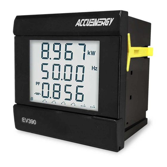
EV/DV300 Series Power Meter
Chapter 1: Introduction
[Cover page]
V:2.0 Revised October 2018
1
Table of
Contents
Previous
Page
Next
Page
1
2
3
4
5
Advertisement
Table of Contents
Need help?
Do you have a question about the EV300 Series and is the answer not in the manual?
Ask a question
Questions and answers
Related Manuals for AccuEnergy EV300 Series
Measuring Instruments AccuEnergy EV390 User Manual
Power meter (55 pages)
Measuring Instruments Accuenergy AcuDC 241 User Manual
Power meter (70 pages)
Measuring Instruments Accuenergy Acuvim-L Series Owner's Manual
Multifunctional power meter (188 pages)
Measuring Instruments Accuenergy Acuvim II User Manual
Power meter acuvim ii series (280 pages)
Measuring Instruments Accuenergy Acuvim II series User Manual
Power meter (350 pages)
Measuring Instruments AccuEnergy Acuvim II Series User Manual
Power meter snmp protocol (23 pages)
Measuring Instruments AccuEnergy Acuvim II User Manual
Bacnet for acuvim ii series power meter (27 pages)
Measuring Instruments AccuEnergy AcuRev 1300 User Manual
3p4w energy meter (121 pages)
Measuring Instruments AccuEnergy AcuRev 2000 User Manual
Smart metering system (225 pages)
Measuring Instruments AccuEnergy AcuRev 2000 User Manual
Smart metering system (270 pages)
Measuring Instruments AccuEnergy AcuDC 240 Series User Manual
Power meter (59 pages)
Measuring Instruments AccuEnergy Acuvim II Series User Manual
Power meter (60 pages)
Measuring Instruments AccuEnergy AcuDC 240 Series User Manual
Power and energy meter (93 pages)
Measuring Instruments AccuEnergy Acuvim II Series User Manual
Power meter (73 pages)
Measuring Instruments AccuEnergy AcuRev 1310 Series User Manual
Din-rail power meter (109 pages)
Measuring Instruments AccuEnergy Acuvim-L Series User Manual
Power meter (83 pages)
This manual is also suitable for:
Dv300 series
Dv30x series
Dv32x series
Ev361
Ev362
Ev382
...
Show all
Ev384
Ev387
Ev390
Dv330
Table of Contents
Print
Rename the bookmark
Delete bookmark?
Delete from my manuals?
Login
Sign In
OR
Sign in with Facebook
Sign in with Google
Upload manual
Upload from disk
Upload from URL


Need help?
Do you have a question about the EV300 Series and is the answer not in the manual?
Questions and answers