Table of Contents
Advertisement
Advertisement
Table of Contents

Subscribe to Our Youtube Channel
Related Manuals for AccuEnergy AcuRev 1310 Series


Summary of Contents for AccuEnergy AcuRev 1310 Series
- Page 1 AcuRev 1310 DIN-Rail Power Meter User's Manual...
- Page 2 Copyright © 2017 V1.00 This manual may not be altered or reproduced in whole or in part by any means without the expressed written consent of Accuenergy.
- Page 3 Please read this manual carefully before installation, operation and maintenance of the AcuRev 1310 series meter. The following symbols in this manual are used to provide warning of danger or risk during the installation and operation of the meters.
-
Page 4: Table Of Contents
4.2 Parameter Settings ....................42 4.2.1 Wiring Method & CT/PT Settings ................. 42 4.2.2 Reactive Power Calculation: ................43 4.2.3 Modbus Communication Options: ..............43 4.2.4 Energy Pulse Output .................... 44 4.2.5 Demand ........................ 45 V: 1.0 Revised: Jan. 2018 www.accuenergy.com... - Page 5 Appendix A – Functions List ..................103 Appendix B Technical Specifications and Parameters ..........104 Appendix C Revision History ..................105 Appendix D Alarm Parameters Comparison Table ........... 105 Appendix E Meter Event Flags: bit32 ................ 106 V: 1.0 Revised: Jan. 2018 www.accuenergy.com...
- Page 6 Welcome to the AcuRev 1310! You have purchased an advanced, versatile, multifunction power meter. Please note the following chapter descriptions in order to utilize the power meter properly. Chapter 1 introduces the basic AcuRev 1310 features and application areas. Chapter 2 introduces the AcuRev 1310 installation and wiring methods in detail. Chapter 3 walks through how to operate the AcuRev 1310 via the display panel, display measurement data and parameter settings.
-
Page 7: Chapter 1: Introduction
AcuRev 1310 DIN-Rail Power Meter Chapter 1: Introduction 1.1 Meter Overview 1.2 Areas of Application 1.3 Product Features... -
Page 8: Meter Overview
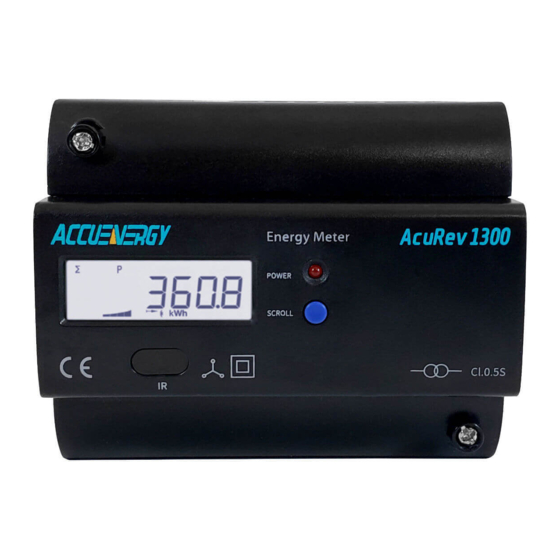
DIN-Rail Power Meter 1.1 Meter Overview The AcuRev 1310 series is a DIN rail-mounted, three phase energy meter that is small in size with high accuracy. The meter is equipped with an easy to read liquid crystal display (LCD) which conveys all the important data. It is ideal for building energy management systems, en- ergy monitoring and energy metering systems. -
Page 9: Areas Of Application
IEC 35mm DIN standard. Clear Display The AcuRev 1310 series features a clear display to provide visibility in all environments. All measurement parameters can be found and easily accessed through the display. The LCD display has backlight support that can aid users in weak lighting environments. - Page 10 It supports both high voltage systems and low voltage systems, as well as both three-phase three-wire systems and three-phase four-wire systems. Users can choose the appropriate wiring configuration for the AcuRev 1310 series meter. The AcuRev 1310 series meter can be used for single phase systems as well.
-
Page 11: Chapter 2: Installation
AcuRev 1310 DIN-Rail Power Meter Chapter 2: Installation 2.1 Appearance and Dimensions 2.2 Installation Methods 2.3 Wiring... - Page 12 Use dry cloth to wipe the meter. ✓ This chapter mainly describes the installation process of the AcuRev 1310 series meter, which is a very important step in using the meter correctly. This chapter provides information and diagrams about how to install the meter. Before installing the meter, please read through this section first.
-
Page 13: Appearance And Dimensions
Chapter 2: Installation 2.1 Appearance and Dimensions Figure 2-1 AcuRev 1310 Front Display Unit: mm 108.0 15.0 17.5 62.5 Front View Side View Figure 2-2 AcuRev 1310 meter Front and Side Dimensions V: 1.0 Revised: Jan. 2018 www.accuenergy.com... -
Page 14: Installation Methods
Humidity 5% to 95% non-condensing. Location AcuRev 1310 series meter should be installed in a dry and dust free environment. Avoid expos- ing the meter to excessive heat, radiation and high electrical noise sources. Installation Steps: This product is DIN railed mounted and fits on a standard 35mm rail. -
Page 15: Wiring
Figure 2-4 Step B 2.3 Wiring The terminals of the AcuRev 1310 series can be accessed by first removing the terminal covers on the meter. 1. To open the terminal cover, remove the seal if applicable, and then unscrew the sealing screws and lift the cover upwards to remove. - Page 16 Figure 2-6 Attaching terminal cover onto meter 3. 3. After inserting the cover, tighten the sealing screws and place the seal. Figure 2-7 V: 1.0 Revised: Jan. 2018 www.accuenergy.com...
-
Page 17: Terminals
• Relay Output: R1, R2 2.3.2 Auxiliary Power Supply: The AcuRev 1310 series meter requires a power supply of 100 ~ 415 Vac at 50/60 Hz. For use of other power supply voltage selections please contact the manufacturer. The meter typically has small power consumption (less than 1W) so the power supply can be an independent power supply, or can also be obtained from the circuit under test. -
Page 18: Voltage Input
2.3.3 Voltage Input: The maximum input voltage for the AcuRev 1310 series meter cannot exceed 400LN/690LL VAC RMS for three phase or 400LN VAC rms for single phase. The voltage input requires a 1A fuse. -
Page 19: Current Input
Please read this section carefully before choosing the suitable wiring meth- od for your power system. In the AcuRev 1310 series meter please make sure that the wiring connection mode and the cor- responding practical application in engineering are correct to ensure the measurement accura- cy of meter. - Page 20 Note: AcuRev 1314-RCT current input does not support neutral current measurement LINE A B C N 1A FUSE Terminal Block V3 V2 V1 AcuRev 1310 LOAD Figure 2-10b – Acurev 1311, 1312, 1313 3LN wiring diagram using 5A/1A CTs V: 1.0 Revised: Jan. 2018 www.accuenergy.com...
- Page 21 PTs. The PTs should be connected as shown below. Note: Only two PTs are needed for this connection LINE A B C 1A FUSE Terminal Block V3 V2 V1 AcuRev 1310 LOAD Figure 2-11a 2LL wiring diagram using 5A/1A CTs and PTs V: 1.0 Revised: Jan. 2018 www.accuenergy.com...
- Page 22 Figure 2-11b 2LL using 333mV, mA and Rogowski Coil CTs Direct Connection, without PT's: LINE A B C 1A FUSE Terminal Block V3 V2 V1 AcuRev 1310 LOAD Figure 2-11c – 3LN– 3 phase delta no neutral wiring diagram using 5A/1A CTs V: 1.0 Revised: Jan. 2018 www.accuenergy.com...
- Page 23 The wiring mode is set to 1LL. Two CT's needed for this connection. Common Voltage: 120V LN/240V LL LINE A N B 1A FUSE Terminal Block V3 V2 V1 AcuRev 1310 LOAD Figure 2-12a 1LL wiring diagram using 5A/1A and CT's V: 1.0 Revised: Jan. 2018 www.accuenergy.com...
- Page 24 The wiring mode is set to 1LN. One CT needed for this connection. Common Voltage for this connection: 120V LINE 1A FUSE Terminal Block V3 V2 V1 AcuRev 1310 LOAD Figure 2-13a - AcuRev 1314 Model 1LN using 5A/1A CT V: 1.0 Revised: Jan. 2018 www.accuenergy.com...
- Page 25 V3 V2 V1 AcuRev 1310 LOAD Figure 2-13b – AcuRev 1311, 1312, 1313 Model 1LN using 5A/1A CT LINE 1A FUSE Terminal Block AcuRev 1310 LOAD Figure 2-13c 1LN using 333mV, mA and Rogowski Coil CT V: 1.0 Revised: Jan. 2018 www.accuenergy.com...
-
Page 26: Relay Output Wiring Diagram
AcuRev 1310 DIN-Rail Power Meter 2.3.5 Relay Output Wiring Diagram 220Vac Auxiliary Power Supply Relay Output Figure 2-14 Relay Output Wiring Diagram V: 1.0 Revised: Jan. 2018 www.accuenergy.com... -
Page 27: Communication
(typical value 120- 300 Ohm, 0.25W) should be used at the end of the circuit (the last device of the chain). • Use RS232/RS485 or USB/RS485 converter with optical isolated output and surge protection. V: 1.0 Revised: Jan. 2018 www.accuenergy.com... -
Page 28: Chapter 3: Operation And Application
AcuRev 1310 DIN-Rail Power Meter Chapter 3: Operation and Application 3.1 Display Panel and Keys 3.2 Display Mode and Key Operations 3.3 Parameter Display and Key Operations 3.4 Settings and Operations 3.5 Meter Configuration 3.6 Energy Pulse Output... -
Page 29: Display Panel And Keys
Four- quadrant reactive power display power. Import icon(right arrow): Displays the energy consumed Export icon(left arrow) displays the energy generated Inductance icon: Inductive load Capacitor icon: Load type Capacitive load unit Unit of the parameter being displayed. V: 1.0 Revised: Jan. 2018 www.accuenergy.com... -
Page 30: Display Mode And Key Operations
The important parameter display mode is the default display mode of the meter. It will display the measurement parameters of the AcuRev 1310 series meter. Users only see the Consumed Active Energy (kWh) parameter unless additional parameters are added through the settings mode. -
Page 31: Parameter Display And Key Operations
Chapter 3: Operation & Application 3.2 Parameter Display and Key Operations The following tables show the All Parameters Display for the different AcuRev 1310 Series Me- ters. Table 3-2 All Parameters Display for AcuRev 1311 Page Parameter Voltage Wiring Check... - Page 32 Phase A Current(A) Phase B Current(A) Phase C Current(A) Total Current(A) System Active Power(kW) Active Power Phase A(kW) Active Power Phase B(kW) Active Power Phase C(kW) Frequency(Hz) Temperature Meter run time Load run time V: 1.0 Revised: Jan. 2018 www.accuenergy.com...
- Page 33 Phase A Current(A) Phase B Current(A) Phase C Current(A) Total Current(A) System Active Power(kW) Active Power Phase A(kW) Active Power Phase B(kW) Active Power Phase C(kW) Frequency(Hz) Temperature Meter run time Load run time V: 1.0 Revised: Jan. 2018 www.accuenergy.com...
-
Page 34: Settings And Operations
The settings mode is where the user can perform most configurations for the AcuRev 1310 me- ter. To enter the settings press the “SET” key which is located under the meters terminal cover. Next the user will be prompted by a password screen. V: 1.0 Revised: Jan. 2018 www.accuenergy.com... - Page 35 The “SCROLL” key is used to move to the next setting page and to change the value of the set- ting when in edit mode. The following tables will show the Setting Display for the different AcuRev 1310 Series Meters. Table 3-6 Setting Display for AcuRev 1311...
- Page 36 P: Real Energy; Q:Reactive Energy Reactive Power Calculation 0:True; 1:Generalized Password 0000-9999 Real-time reading mode 1: Primary; 2: Secondary Wiring configuration 3LN; 1LN; 1LL;2LL 5A/1A(5A Current Input) 80mA/100mA/200mA(mA Current Input) 1~50,000 50~400 50~1000000 Pulse Constant 1~60000 V: 1.0 Revised: Jan. 2018 www.accuenergy.com...
-
Page 37: Meter Configuration
3.5 Meter Configuration 3.5.1 Initial Setup The AcuRev 1310 series meters need to be configured correctly in order for it to measure data accurately. For the initial meter setup, the wiring mode, PT and CT ratios need to be configured on the me- ter. - Page 38 The AcuRev 1310 series supports the transmission of energy pulses through the P1 and P2 ter- minals of the meter. The AcuRev 1310 series uses the KYZ output to transmit test pulses that are proportional to the accumulated energy that the meter is measuring.
- Page 39 Note: if no PTS were used, then enter the PT ratio as the default on the meter, i.e. 400/400. If the CT2: 333mV, RCT or 80/100/200mA, consider this as 1A for the calculation. • Divide 10kWh by 22,000 i.e. (10/22000) kWh = (1/2200) kWh. V: 1.0 Revised: Jan. 2018 www.accuenergy.com...
- Page 40 With the pulse output circuit and settings configured the pulse output can be tested. Inject the meter with both voltage and current to ensure that the meter will accumulate energy and also output the pulses based on the above settings. V: 1.0 Revised: Jan. 2018 www.accuenergy.com...
-
Page 41: Chapter 4 Functions Functions And Software
AcuRev 1310 DIN-Rail Power Meter Chapter 4 Functions Functions and Software 4.1 Introduction to AcuRev 1310 Utility Software 4.2 Parameter Settings 4.3 Real Time Metering 4.4 Measurement Function 4.5 Event Logging 4.6 Alarm Function 4.7 Incorrect Connection Detection 4.8 Sealing Function 4.9 Device Information... -
Page 42: Introduction To Acurev 1310 Utility Software
Software. The AcuRev 1311 is not supported. 4.1 Introduction to AcuRev 1310 Utility Software The AcuRev 1310 series meters can be accessed through the AcuRev 1310 Utility Software. The software can be downloaded from the Accuenergy website under Downloads, or using the following link: https://accuener- gy.com/page/support/download-manuals-datasheets-software-firmware... - Page 43 Note: The baud rate, parity, and device address must be the same on the meter as well as the AcuRev Utility Software. The following figure shows the screen when you first open AcuRev 1310 Utility Software. V: 1.0 Revised: Jan. 2018 www.accuenergy.com...
-
Page 44: Parameter Settings
DIN-Rail Power Meter 4.2 Parameter Settings The AcuRev 1310 series meters requires general settings so that the meters can work according to the correct specification. The general settings can be found by clicking on the “Settings” menu on the main menu toolbar and selecting “General Settings” on the top menu bar of the software. -
Page 45: Reactive Power Calculation
Modbus. The red box in Figure 4-5 shows how it is displayed in the AcuRev 1310 Utility Software. Figure 4-5 Meter address, baud rate, and meter parity settings on AcuRev 1310 Utility software V: 1.0 Revised: Jan. 2018 www.accuenergy.com... -
Page 46: Energy Pulse Output
AcuRev 1310 DIN-Rail Power Meter 4.2.4 Energy Pulse Output The AcuRev 1310 series supports the transmission of the pulses through the P1 and P2 terminals of the meter. Active: P1, P2 terminal output pulse is based on the active energy pulse. -
Page 47: Demand
You can see the Demand calculations in the red box of the figure below. Under the dropdown menu in “Compute Mode” is where you can find the four different methods mentioned above. Figure 4-8 the Demand Calculation Modes in the General Settings of AcuRev1310 Utility Software V: 1.0 Revised: Jan. 2018 www.accuenergy.com... -
Page 48: Sealing Option
• Choosing “Run-time and Load-time” the content of the run and load time will be sealed. • Choosing “Communication” the content of communication time will be sealed. Note: To change the corresponding time it must occur once the seal is open. V: 1.0 Revised: Jan. 2018 www.accuenergy.com... -
Page 49: Communication Permission
Note: In the low permission you can update to high permission through updating the commu - nication permission. After 30 minutes of updating to high permission, the meter would lower its permission to “low permission” automatically, to keep the meters safety. V: 1.0 Revised: Jan. 2018 www.accuenergy.com... -
Page 50: Display Parameters
“SCROLL” key. The figure below shows the Display Scan Parameters in the red box. Figure 4-12 the Display Scan Parameters in the General Settings V: 1.0 Revised: Jan. 2018 www.accuenergy.com... -
Page 51: Energy Decimal Places & Ro Output Mode
4-14. All metering parameters can be found by clicking on ‘Readings’ from the main menu toolbar and select ‘Real-Time Metering’. Figure 4-14 Real-Time Metering in the AcuRev 1310 Software V: 1.0 Revised: Jan. 2018 www.accuenergy.com... - Page 52 The lower half of the Energy1 page displays the consumed active energy readings that have been accumulated under the Time of Use (TOU) function of the meter. V: 1.0 Revised: Jan. 2018 www.accuenergy.com...
-
Page 53: Measurement Function
Users can also provide initial values for their AcuRev 1310 series models (only 1312, 1313, and 1314 applicable) to start to accumulate energy from. To do this, users must have sufficient per- mission, which can be obtained from the General Settings page. - Page 54 “TOU Parameter Settings” for details). The TOU function will be disabled if the TOU calendar is set up incorrectly. If no errors are found in the calendar and the TOU function is en- abled, TOU energy accumulation will commence. V: 1.0 Revised: Jan. 2018 www.accuenergy.com...
-
Page 55: Tou Seasons
Fill in the appropriate slots in the TOU (Time of Use) Seasons based on the number in the “Season Settings”. If the “Season Settings” is set to 2 then only the first 2 slots of the “TOU Seasons” must be filled in. V: 1.0 Revised: Jan. 2018 www.accuenergy.com... - Page 56 The time should be organized in chronological order (The earliest time comes first and the later time follows). Note: Entering the time in the wrong order will cause the TOU function to be disabled V: 1.0 Revised: Jan. 2018 www.accuenergy.com...
-
Page 57: Daylight Saving Time (Dst)
Note: Make sure to Click “Update Device” after making any changes in order to save the set - tings. If no errors are found then the TOU energy accumulation will begin. Figure 4-21 Daylight Saving Time Setting on AcuRev 1310 Utility Software V: 1.0 Revised: Jan. 2018 www.accuenergy.com... -
Page 58: Event Logging
DIN-Rail Power Meter 4.5 Event Logging The AcuRev 1310 series supports event logging of important parameters and operation. The Event logging page can be found by clicking on the ‘Readings’ menu and selecting ‘Event Log’. Figure 4-22 shows how the Event Log will look in the AcuRev 1310 Utility Software. - Page 59 • Event of Clear Demand The meter will record when the Demand parameters are cleared. It records up to 3 groups of Clear Demand Events. Figure 4-25 Event of Opening Meter Cover in AcuRev 1310 Utility Software V: 1.0 Revised: Jan. 2018 www.accuenergy.com...
-
Page 60: Alarm Function
To set up the alarms, users must first select an alarming parameter, a condition, a delay time (ms), and an alarming output. Users can set a maximum of 12 alarms. Figure 4-27 shows you the Alarm Settings. V: 1.0 Revised: Jan. 2018 www.accuenergy.com... - Page 61 Chapter 4: Functions and Software Figure 4-27 Alarm Settings Page on AcuRev 1310 Utility Software V: 1.0 Revised: Jan. 2018 www.accuenergy.com...
-
Page 62: Configuring The Alarm
4.6.2 Reading the Alarm To read the alarm log on the AcuRev 1310 Series Utility Software you click on the ‘Readings’ menu and select ‘Alarm Log’. The alarm log can be seen in Figure 4-28. Figure 4-28 Alarm Log on AcuRev 1310 Series Utility Software V: 1.0 Revised: Jan. -
Page 63: Incorrect Connection Detection
The alarm log can store up to 20 groups of alarm events. 4.7 Incorrect Connection Detection The AcuRev 1310 series meter has a connection detection function. This function detects the connections or wiring to the meter based on the wiring mode configuration. -
Page 64: Sealing Function
4.8 Sealing Function The AcuRev 1310 series meter supports a sealing function. When the seal is open, the read write functions are available. When the seal is closed some of the meters functions which include parameters and optional parameters will be blocked and limited. These parameters can still be accessed by keys communication, but cannot be modified (Write function not available when seal is closed) when sealed status is present. - Page 65 Total Reactive Energy Tariff 4 932H-933H Net Reactive Energy 934H-935H Net Reactive Energy Tariff 1 936H-937H Net Reactive Energy Tariff 2 938H-939H Net Reactive Energy Tariff 3 93AH-93BH Net Reactive Energy Tariff 4 93CH-93DH Import Reactive Energy V: 1.0 Revised: Jan. 2018 www.accuenergy.com...
- Page 66 Table 4-6 Address Parameter Description Communication TOU Related Parameters Time-Division Energy Setting 402H-40EH Parameter 1 Time-Division Energy Setting 420H-5F3H Parameter 2 Daylight Saving Time Related Parameters Daylight Saving Time Related 350H-367H Parameters V: 1.0 Revised: Jan. 2018 www.accuenergy.com...
-
Page 67: Device Information
Users can also configure the device clock of the meter from this page to the time of the comput- er the meter is connected to or give it any other specific time. V: 1.0 Revised: Jan. 2018 www.accuenergy.com... -
Page 68: Chapter 5: Communication
AcuRev 1310 DIN-Rail Power Meter Chapter 5: Communication 5.1 Modbus Protocol Information 5.2 Communication Format 5.3 Application Details... -
Page 69: Modbus Protocol Information
Error checking 5.1.2. Frame When the data frame reaches the AcuRev 1310 series meter (slave device), the meter removes the data frame’s header, and reads the data. If there is no error, then the meter will implement the data’s task. Once the task is completed, the meter will put its own data with the acquired header and send back the frame to the master device that queried the meter. -
Page 70: Communication Format
Addr: Slave device address Fun: Function code Data start register hi: High byte of starting register address Data start register lo: Low byte of starting registers address V: 1.0 Revised: Jan. 2018 www.accuenergy.com... - Page 71 This function code allows the user to obtain the measurement data from the AcuRev 1310 series meter. Below is an example of a query for reading three of the AcuRev 1310 series energy parameters. The query is requesting the total active energy, tariff 1 active energy and tariff 2 active energy from the meter device address of 17.
-
Page 72: Application Details
CRC16 lo 5.3 Application Details 5.3.1 Data Types The data types supported by the AcuRev 1310 series meter have the following meanings: Bit-binary value Word-16 bit unsigned integer using one register that contains 2 bytes. The data range is 0-65535. -
Page 73: Parameter Address Table
100H Word “The Result of Wiring Check Wiring Check” 0x0A: Seal sealed 101H Seals Status Word Others: Seal opened System Parameter System parameters decides the devices working mode. 10H- read command 03H- write command V: 1.0 Revised: Jan. 2018 www.accuenergy.com... - Page 74 Used for revise Communication 20BH Password Word Operation Authority, verify pass- word when get new password 0000-9999 Note: To get new password needs 20CH New Password Word correct current password, incor- rect current password in invalid. V: 1.0 Revised: Jan. 2018 www.accuenergy.com...
- Page 75 Energy Pulse 219H Word 20-100 ms Width Energy Display 21AH Word 0,1,2,3 Decimal Relay Operating 0: Relay Control 21BH Word Mode 1: Alarm Output Connection De- 0: No Enable 21CH Word tection Enable 1: Enable V: 1.0 Revised: Jan. 2018 www.accuenergy.com...
- Page 76 Phase Angle of V2 to V1 V1/V2 203CH-203DH 8252-8253 Phase Angle of V23 to float V12/V23 Phase Angle of V3 to V1 V1/V3 203EH-203FH 8254-8255 float Phase Angle of V31 to V12 V12/V31 V: 1.0 Revised: Jan. 2018 www.accuenergy.com...
- Page 77 8270-8271 Dword 0-9999999999kWh Imported Total Active Energy 2050H-2051H 8272-8273 Dword 0-9999999999kWh Imported Phase A Total Active Energy 2052H-2053H 8274-8275 Dword 0-9999999999kWh Imported Phase B Total Active Energy 2054H-2055H 8276-8277 Dword 0-9999999999kWh Imported Phase C V: 1.0 Revised: Jan. 2018 www.accuenergy.com...
- Page 78 207EH-207FH 8318-8319 Dword 0-9999999999kWh Total Reactive Imported 2080H-2081H 8320-8321 Dword 0-9999999999kWh Q4 Phase A Total Reactive Imported 2082H-2083H 8322-8323 Dword 0-9999999999kWh Q4 Phase B Total Reactive Imported 2084H-2085H 8324-8325 Dword 0-9999999999kWh Q4 Phase C V: 1.0 Revised: Jan. 2018 www.accuenergy.com...
- Page 79 1: format 2 (non fixed date) Format 1: Fixed Date 352H DST Start Month Word 1~12 353H DST Start Day Word 1~31 354H DST Start Hour Word 0~23 355H DST Start Min Word 0-59 V: 1.0 Revised: Jan. 2018 www.accuenergy.com...
- Page 80 0: Sunday 363H DST Ending Day Word 1~6 Monday-Satur- 364H DST Ending Week Word 365H DST Ending Hour Word 0~23 DST Ending Min- 366H Word 0~59 DST Ending 367H Adjust time (Unit: Word 1~120 minute) V: 1.0 Revised: Jan. 2018 www.accuenergy.com...
- Page 81 1-4 Only can change Current number when the TOU Tariff 40DH 1037 of tariffs to config- Word Number is set as 1, Communication TOU Settings – 40EH 1038 Word Only ‘0x0A” Valid reset to factory default V: 1.0 Revised: Jan. 2018 www.accuenergy.com...
- Page 82 00-00 00 1085 Day, Schedule Table number Time Zone 11: 1086- starting Month, 43EH-440H 00-00 00 1088 Day, Schedule Table number Time Zone 12: 1089- starting Month, 441H-443H 00-00 00 1091 Day, Schedule Table Number V: 1.0 Revised: Jan. 2018 www.accuenergy.com...
- Page 83 1124 Minute, Tariff Number) Schedule Table 1125- 1, 10th segment 465H- 467H 00:00 00 1127 (Hour, Minute, Tariff Number) Schedule Table 1128- 1, 11th segment 468H- 46AH 00:00 00 1130 (Hour, Minute, Tariff Number) V: 1.0 Revised: Jan. 2018 www.accuenergy.com...
- Page 84 Minute, Tariff Number) Schedule Table 8, 1st – 14th 1392- 570H- 599H segment (Hour, 00:00 00 1433 Minute, Tariff Number) The 1st special 1434- day (Month, Day, 59AH- 59CH 03-12 01 1436 Schedule Table Number) V: 1.0 Revised: Jan. 2018 www.accuenergy.com...
- Page 85 00-00 00 1460 Schedule Table Number) The 10th special 1461- day (Month, Day, 5B5H- 5B7H 00-00 00 1463 Schedule Table Number) The 11th ~30th special day 1464- 5B8H- 5F3H (Month, Day, 1523 Schedule Table Number) V: 1.0 Revised: Jan. 2018 www.accuenergy.com...
- Page 86 Power Demand 1 Dword (Second always is 0) Peak Time Exported Active 1822H-1823H 6172-6173 Power Demand 2 Float Xx.xxxx kw Peak Exported Active YY/MM/DD/hh/mm/ss 1824H-1826H 6174-6175 Power Demand 2 Dword (Second always is 0) Peak Time V: 1.0 Revised: Jan. 2018 www.accuenergy.com...
- Page 87 Reactive Power Float Xx.xxxx kw Demand Peak Total Exported YY/MM/DD/hh/mm/ss 184CH-184EH 6206-6207 Reactive Power De- Dword (Second always is 0) mand Peak Time Exported Reactive 184FH-1850H 6208-6209 Power Demand 1 Float Xx.xxxx kw Peak V: 1.0 Revised: Jan. 2018 www.accuenergy.com...
- Page 88 YY/MM/DD/hh/mm/ss 1870H-1872H 6234-6235 Demand Peak Dword (Second always is 0) Time Phase C Current 1873H-1874H 6236-6237 Xx.xxxx A Demand Peak Phase C Current YY/MM/DD/hh/mm/ss 1875H-1877H 6238-6239 Demand Peak Dword (Second always is 0) Time V: 1.0 Revised: Jan. 2018 www.accuenergy.com...
- Page 89 Alternative 7F11H 32523 Season 3 of Week- word –7F18H -32536 end Alternative 7F19H Season 4 of Week- 32537-32538 word –7F20H end Alternative 7F21H 32539 Season 5 of Week- word –7F28H -32552 end Alternative V: 1.0 Revised: Jan. 2018 www.accuenergy.com...
- Page 90 Time Time segment segment segment segment segment segment segment segment table 8 table 7 table 6 table 5 table 4 table 3 table 2 table 1 error error error error error error error error V: 1.0 Revised: Jan. 2018 www.accuenergy.com...
- Page 91 0: larger; 707H 1799 Setpoint Value Word 1: equal; 2: less 708H 1800 Delay Time Word 0~3000 (x10ms) Alarm Parameter Setting for the 2nd 12th group 709H- 1801- The same as Word 703BH 1851 above V: 1.0 Revised: Jan. 2018 www.accuenergy.com...
- Page 92 -1001H -4097 Uint16 1002H 4098 Length Uint16 1003H 4099 Well known value regis- 1004H Manufacturer String tered with SunSpec for Accuenergy 4100-4115 -1013H compliance Manufacturer specific 1014H Model String AcuRev 1310 4116-4131 value (32 characters) -1023H Manufacturer specific 1024H Options...
- Page 93 Active Power: AcuRev 1310 Watts Phase A: SunSpec; 1058H 4184 Int16 0~9999 W Total Active Pow- er: AcuRev 1310 Watts Phase A: SunSpec; Phase 1059H 4185 Int16 0~9999 W A Active Power: AcuRev 1310 V: 1.0 Revised: Jan. 2018 www.accuenergy.com...
- Page 94 0~9999 VAR Power: AcuRev 1310 VAR Phase B: SunSpec; 1063H 4195 Phase B Reactive Int16 0~9999 VAR Power: AcuRev 1310 VAR Phase C: SunSpec; 1064H 4196 Phase C Reactive Int16 0~9999 VAR Power: AcuRev 1310 V: 1.0 Revised: Jan. 2018 www.accuenergy.com...
- Page 95 4211-4212 Spec; Total Active Acc32 0-999999999 kWh -1074H Energy Imported: AcuRev 1310 Total Watt-hours Imported Phase A: SunSpec; 1075H 4213-4214 Total Active En- Acc32 0-999999999 kWh -1076H ergy Imported in Phase A: AcuRev 1310 V: 1.0 Revised: Jan. 2018 www.accuenergy.com...
- Page 96 Exported phase C: SunSpec; Total 1082H 4226-4227 Apparent Power Acc32 0-999999999 kVAh -1083H Exported in Phase C: AcuRev 1310 Total VA-hours Imported: 1084H SunSpec; 4228-4229 Acc32 0-999999999 kVAh -1085H Total Apparent Power Imported: AcuRev 1310 V: 1.0 Revised: Jan. 2018 www.accuenergy.com...
- Page 97 1097H 4247-4248 Imported Q2 Acc32 0-999999999 kvarh -1098H Phase A Total VAR-hours 1099H 4249-4250 Imported Q2 Acc32 0-999999999 kvarh -109AH Phase B Total VAR-hours 109BH 4251-4252 Imported Q2 Acc32 0-999999999 kvarh -109CH Phase C V: 1.0 Revised: Jan. 2018 www.accuenergy.com...
- Page 98 All the energy use the 10ADH 4269 Sussf ratio X PT ratio: same SF AcuRev 1310 10AEH Meter Evenet- 4270-4271 Bitfield32 R -10AFH Flags SunSpec_end_ 10B0H 4272 Uint16 0xFFFF ID: SunSPec; SunSpec_end_ 10B1H 4273 Uint16 0x0000 length: SunSpec V: 1.0 Revised: Jan. 2018 www.accuenergy.com...
- Page 99 Input reactive power Float xx.xxxx kvar 1643H-1645H 5699-5701 max demand 3 and Dword YYMMDDhhmmss occur time 1646H-1647H 5702-5703 Input reactive power Float xx.xxxx kvar 1648H-164AH 5704-5706 max demand 4 and Dword YYMMDDhhmmss occur time V: 1.0 Revised: Jan. 2018 www.accuenergy.com...
- Page 100 3: Reset Meter Opening Re- cord; 4: Reset Alarm; 5: Reset Meter Operation Time; 6: Reset Time of Meter Opera- tion with Load; Last 2 Event Reset Record 1D06H-1D09H 7430-7433 Last 3 Event Reset Record 1D0AH-1D0DH 7434-7437 V: 1.0 Revised: Jan. 2018 www.accuenergy.com...
- Page 101 Range Default Model Description Type Number Decimal Total Times of Demand 1B00H-1B01H 6912-6913 Word 0~0xFFFFFFFF Reset Last time open cover record 1B02H-1B04H 6914-6916 Occur time Word YYMMDDhhmmss Last 2 – 3 time 1B05H-1B0AH 6917-6916 V: 1.0 Revised: Jan. 2018 www.accuenergy.com...
- Page 102 7426-7428 Occur Time Word YYMMDDhhmmss 1: clear the pro- gramming records 2: clear demand Event clearance data 1D05H 7429 Word flag records 3: clear open cover records Last 2 – 3 time 1D06H-1D0DH 7430-7437 V: 1.0 Revised: Jan. 2018 www.accuenergy.com...
- Page 103 1: ON 0: OFF RO control (05H) Table 5-29 RO Control function-05H Write Modbus Address Parameter Register Data Type Data Range Default Model (HEX) Description Number FF00: ON 0000H RO control Word 0000: OFF V: 1.0 Revised: Jan. 2018 www.accuenergy.com...
-
Page 104: Appendix
AcuRev 1310 DIN-Rail Power Meter Appendix Appendix A - Functions List Appendix B - Technical Data and Specification Appendix C - Revision History Appendix D - Alarm Parameters Comparison Table Appendix E - Meter Event Flags: 32 bit... -
Page 105: Appendix A - Functions List
■ Θ Θ Θ Relay Output RS-485 Modbus-RTU ■ ■ ■ Wiring Check ■ ■ ■ ■ Temperature ■ ■ ■ ■ ■ : Fixed function Θ : Optional function Blank: Function Not Supported V: 1.0 Revised: Jan. 2018 www.accuenergy.com... -
Page 106: Appendix B Technical Specifications And Parameters
Load Current 10mA(max) Relay Output Load Voltage 250Vac 30Vdc Max Load Current 5A (Resistive Load) Isolation Voltage 2000Vac(1min) Action Time 10ms Mechanical Life 20 million times Above 50,000 times Electrical Life (5A, 250Vac, Resistive Load V: 1.0 Revised: Jan. 2018 www.accuenergy.com... -
Page 107: Appendix C Revision History
Phase C Apparent Power Power Total Reactive Power Phase A Reactive Phase B Reactive Power Power Phase C Reactive Power Total Power Factor Phase A Power Factor Phase B Power Factor Phase C Power Fac- V: 1.0 Revised: Jan. 2018 www.accuenergy.com... -
Page 108: Appendix E Meter Event Flags: Bit32
Bit7 Bit6 Bit5 Bit4 Bit3 Bit2 Bit1 Bit0 M_EVENT_ M_ EVENT_ M_ EVENT_ M_ EVENT_ M_ EVENT_ M_ EVENT_ Reserved Reserved Missing_ Over_ Volt- Over_ Cur- Low_ PF Under_ Power_ Sensor rent Voltage Failure V: 1.0 Revised: Jan. 2018 www.accuenergy.com... - Page 109 MAKE ENERGY USAGE SMARTER ACCUENERGY (CANADA) INC. TF: 1-877-721-8908 INT: +1-416-497-4100 2 Lansing Square, Suite 700 FAX: +1-416-497-4130 Toronto, ON M2J 4P8, Canada E: marketing@accuenergy.com...
Need help?
Do you have a question about the AcuRev 1310 Series and is the answer not in the manual?
Questions and answers