Truma AquaGo basic Operating And Installation Instructions
Lp gas instant water heater
Hide thumbs
Also See for AquaGo basic:
- Operating and installation instructions (140 pages) ,
- Operating instructions manual (44 pages) ,
- Frequently asked questions manual (16 pages)
Table of Contents
Advertisement
Advertisement
Table of Contents

Subscribe to Our Youtube Channel
Related Manuals for Truma AquaGo basic


Summary of Contents for Truma AquaGo basic
- Page 1 Truma AquaGo™ LP Gas Instant Water Heater Model: Truma AquaGo™ basic (DLE6AB) * Truma AquaGo™ comfort (DLE6AC) * Truma AquaGo™ comfort plus (DLE6ACP) * * Patent Pending Operating instructions Page 2 Installation instructions Page 19 To be kept in the vehicle!
-
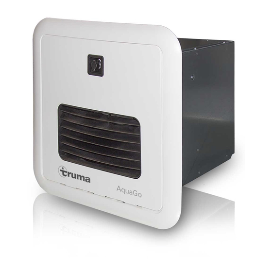
Page 2: Overview / Designation Of Parts
Truma AquaGo™ instant water heater (appliance) Overview / Designation of parts LED 1 4 26 Power Power LED 2 LED 3 Fig. 1 (Unit casing/Frame partially omitted) Fig. 2 (rear view of appliance) Legend 16 Water flow sensor 1 Cold water connection 1/2 inch NPT... -
Page 3: Table Of Contents
Table of contents Intended use Overview / Designation of parts ........2 The Truma AquaGo™ instant water heater (appliance) may be Intended use ............... 3 used only to heat tap water in recreational vehicles (RVs) that Prohibited use ..............3 are used for recreation, travel or camping. -
Page 4: Consumer Safety Information
• Do not place articles on or against the ap- Consumer Safety Information pliance. Do not lean any objects against the water heater’s access door or place any foreign objects within 61 cm (2 feet) of the Safety symbols and signal words access door. - Page 5 • LP tanks must be filled by a qualified gas While driving supplier only. • To avoid damage, make sure the access door (Fig. 1 – 20) to the appliance is closed before • Hot water can be dangerous, especially for moving the RV, as follows: infants, children, the elderly or infirm.
-
Page 6: Safety Features
Monitoring of hot water temperature A water over temperature switch avoids excessively high wa- • Only use Truma AquaGo™ decalcification ter temperatures in case of an error. tablets to decalcify the appliance to avoid damage and the voiding of your warranty. -
Page 7: Operating Instructions
Pressure relief valve Operating instructions Scalding injury from hot water and/or tampering with the pressure relief valve! Read and follow the “Consumer Safety Instructions” be- • Never actuate the pressure relief valve as long as the ap- fore operating the appliance. pliance is still hot. -
Page 8: Access Door
Access door Removing the access door 1. Open the access door to Position . Opening the access door 2. Move the access door upwards to remove it. 1. Turn the turn lock counterclockwise to the vertical position. open Fig. 4 •... -
Page 9: Starting The Appliance
Check the appliance for the following points before each use. the bath or shower. In case of damage, contact an authorised Truma service pro- • Do not leave a child or an infirm person in the bath vider and do not operate the appliance. -
Page 10: Operating Modes (Control Panel)
AquaGo™ basic Clean DECALCIFICATION • The operating mode is set automatically to “BASIC”. Only AquaGo™ comfort / AquaGo™ comfort plus. See “Decalcification” on Page 14. • The appliance is now ready for use. For safety reasons, after 30 seconds the de- •... -
Page 11: Winter Operation
Winter operation Winterising Risk of damage in frosty conditions. Severe damage to the water system components and the appliance! In frosty conditions there is a risk that water in pipes, taps and appliances could freeze. This can cause considerable damage. Any damage caused by freezing or an unsuitable winteris- ing fluid will not be covered by warranty. -
Page 12: Aquago™ Technical Data
AquaGo™ technical data Maintenance Repairs must be performed by a certified service technician. Nominal input power 61.9 MJ/h Truma recommends that the appliance be serviced annually (calorific value) by a certified service technician. Verify proper operation after Fuel propane gas servicing. - Page 13 Latch Danger of crushing/pinching of fingers when the Easy Drain Lever is closed! • Never put fingers between Easy Drain Lever and water inlet filter or latch. If, during installation, it is difficult to install the filter car- tridge, use a small amount of soap on the O-rings. Never use grease because the O-rings are not resistant to grease.
-
Page 14: Decalcification
– Allow about 3 hours for decalcification. The appliance works on its own for most of this time. You can have these models decalcified by a Truma service • Sensitive surfaces (e. g. marble) may be damaged through partner. Please contact the following address: contact with the decalcification agent. - Page 15 To make sure that the appliance and the water pipes • Fill the water inlet filter with 6 Truma AquaGo™ decalcifi- contain no decalcification agent, empty the water sys- cation tablets (content of one blister pack).
-
Page 16: Interrupt Decalcification
Electric antifreeze kit * Tasks within the RV Truma offers an Electric antifreeze kit (part no. 77400-01) that keeps the appliance frost-free to - 20 °C while you are driving • Turn on fresh water supply or switch on water pump. -
Page 17: Troubleshooting
450 kPa (4.5 bar) (rural or urban connection), a water pressure reducer must be used. Install a water pressure reducer (e.g. Truma water pressure regulator) at the fresh water supply. Water cannot expand in the water system. -
Page 18: Truma Warranty Policy
• The company will only provide service on presentation • Cleaning of the system or cleaning and adjustment of the of proof of purchase, on either the Truma product, or the gas system. This is considered to be a part of normal prod- Caravan / RV / Pleasure Craft in which the Truma product uct maintenance. -
Page 19: Installation Instructions
• This appliance must be installed in accordance with and wet roads. the Australian gas code AS/NZS 5601. • Installation must be performed by an authorised Truma recommended installer, service agency, or OEM. Improper installation, alteration, service, or maintenance can cause Risk of poisonous exhaust gases due to improper property damage, personal injury, or loss of life. -
Page 20: Preparing The Gas Connection
4. Make sure that the front edge of the opening is surrounded • Make sure that the gas line to the appliance is able to sup- by a solid frame to firmly anchor the appliance. If needed, ply the maximum required quantity of gas 61,9 MJ/h, with- build an appropriate frame (Fig. -
Page 21: Gas Rear Connection
• Keep the length of the water pipes as short as possible. Truma offers a rear installation gas connection kit (part no. 77000-37500) if installation from the back of the appliance is • Because of the risk of frost, install water pipes only required. -
Page 22: Connection Diagrams
Connection diagrams • The drawings are not intended to describe a complete system. It is up to the certified service technician to determine the necessary components for and configuration of the particular system being installed (for example an additional surge protector). •... -
Page 23: Mounting The Control Panel
Mounting the control panel Installing the appliance Only AquaGo™ comfort / AquaGo™ comfort plus Before installation, read “Preparing for installation” on Page 19 and the following. • Damage to the control panel from wet- ness and moisture. You must install the control panel at a place inside the RV that is protected against moisture and wetness. -
Page 24: Gas Connection
Gas connection • Fasten the cover plate to the appliance (see Fig. 23): – Position the cover plate. – Screw the cover plate only loosely. Start with screw 1. – Align the cover plate. – Uniformly tighten all 8 screws. Risk of explosion or poisoning due to improper installation! •... -
Page 25: Connecting The Gas Line (Gas Rear Connection)
• Risk of poisoning and/or explosion! Improper tightening of the cable tie could result in gas/ex- haust entering the RV. • Close the cable tie so that the gas pipe grommet (side) tightens the gas pipe passage (see Fig. 27). A cable tie is provided with the appliance. -
Page 26: Functional Check
Checking for gas leaks Control unit Risk of death and personal injury through fire and/or explosion! • DO NOT use matches, candles or other sources of ignition when checking for gas leaks. Gas pipe grommet (side) • After the gas supply is connected, check for gas leaks at all gas connections. -
Page 27: Appendix A - Error Codes
1. Write down the flashing intervals and check the list below. 2. Reset the appliance: – Switch off the appliance. / – Wait 5 seconds. / – Switch the appliance on again. 3. If an error code is still displayed, contact an authorised Truma service center. Error Flash code... - Page 28 This page intentionally left blank.
-
Page 29: Appendix B - Functional Diagram
APPENDIX B – Functional Diagram Fig. 34... - Page 30 This page intentionally left blank.
-
Page 31: Appendix C - Spare Parts (All Models)
APPENDIX C – Spare Parts (all models) 35 (36, 37) Fig. 35 Item Part no. Component Item Part no. Component Ref. Ref. 1 NYA Flue Duct Assembly 21 – – 2 NYA Flue Duct gasket 22 NYA Upper housing Assembly 3 NYA Air Overheat Switch 23 NYA... - Page 32 This page intentionally left blank.
-
Page 33: Appendix D - Electrical Connection Diagram
APPENDIX D – Electrical Connection Diagram Fig. 36... -
Page 34: Appendix E - Notes For Painting The Access Door And Cover Plate
APPENDIX E – Notes for painting the access door and cover plate Important Information Work after painting Observe all safety notes/instructions for painting the ac- 7. Remove all masking. cess door and cover plate. 8. Assemble the venting grid and the turn lock in the reverse The following parts (see Fig. - Page 35 Cover plate Webbing Screws (4 x) Venting grid Screws (4 x) Access door Turn lock Clips Clips Fig. 37 Detail A Detail A Flue fan Turn lock opening Tape Remove Masked area Cover plate Outer surface of access door Masking of the venting grid opening from the back side Fig.
- Page 36 In Australia, always notify the Dometic Service Centre if problems are encountered; in other countries the relevant service partners should be contacted (www.truma.com). Having the equipment model and the serial number ready (see type plate) will speed up processing. Dometic Pty Ltd...
Need help?
Do you have a question about the AquaGo basic and is the answer not in the manual?
Questions and answers