
Related Manuals for CEL-MAR ADA-4028LA


Summary of Contents for CEL-MAR ADA-4028LA
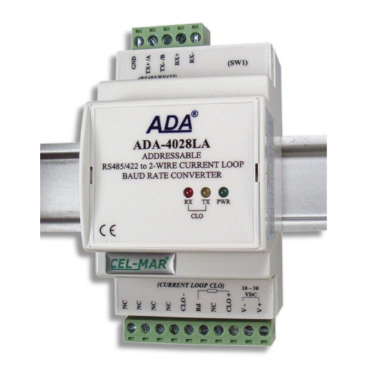
- Page 1 ADA-4028LA User manual ADA-4028LA Addressable RS485/422 to 2-WIRE Current Loop CLO Baud Rate Converter Copyright © 2001-2017 CEL-MAR sp.j. io_ada-4028la_v4.02_en...
-
Page 2: Table Of Contents
ADA-4028LA Contents 1. GENERAL INFORMATION..................................3 1.1. WARRANTED INFORMATION............................... 3 1.2. GENERAL CONDITIONS FOR SAFE USE............................ 3 1.3. CE LABEL....................................... 3 1.4. ENVIRONMENTAL PRESERVATION............................3 1.5. SERVICE AND MAINTENANCE..............................3 1.6. PACK CONTENTS..................................3 2. PRODUCT INFORMATION..................................3 2.1. PROPERTIES....................................3 2.2. -
Page 3: General Information
1.1. WARRANTED INFORMATION The ADA-4028LA converter is covered by a two year warranty from date of sale. In case of being damaged it will be repair or the damaged component will be replace. The warranty does not cover damage caused from improper use, materials consumption or any unauthorized changes. -
Page 4: Description
RS485/422 bus created by the use ADA-4028LA, is possible to connect 32 devices, operating in half duplex mode (query /response) on 2 or 4 wires multipoint bus or full duplex on 4-wire bus. To Current Loop CLO bus created by the use ADA-4028LA (active), is possible to connect 4 devices operating in half duplex mode. -
Page 5: Current Loop Transmitter & Receiver
3.2. CONNECTION TO PC The ADA-4028LA can be connected to RS232 port or USB of PC by the use of additional converter eg. RS232 to RS485 (ADA-1040) or USB to RS485 (ADA-I9140). The connection is made via RS485 bus or RS422 bus, as on the figure bellow. -
Page 6: Connection To Rs485/422 Bus
Fig. 4. The 2-wire connection of ADA-4028L to PC by the use of USB to RS485/RS422 converter ADA-I9140/ADA-I9141 3.3. CONNECTION TO RS485/422 BUS The RS485/RS422 interface at ADA-4028LA converter is available on terminal block described as: Tx+/A, Tx-/B, Rx+, Rx-. Below are shown connection of ADA-4028LA converter to RS485(4W) bus and RS485(2W) bus. -
Page 7: Connection To Rs485 (2-Wire) Bus
Example connection of Rt are shown on Fig. 5 & 6. Resistor Rt = 120 W, 5%, 0.25W of a 2 pc. is complete with the device ADA-4028LA. -
Page 8: Connection Of Device With Passive Interface Clo
CLO+ Tx- / B CLO- Vss- Vss+ Power adapter Fig. 7. Example connection of device with passive CLO interface eg. energy counter to ADA-4028LA 3.3.5.2. CONNECTION OF DEVICE WITH ACTIVE INTERFACE CLO Device with active CLO interface ADA-4028LA PASSIVE RS485... -
Page 9: Connection Of 4 Devices With The Passive Clo Interface
3.4. POWER SUPPLY The power supply to ADA-4028LA should be DC (regulated) from the scope 10 V= to 30V= and nominal power more then 2W. The power cable from DC power supplies to the device must not be longer than 3m. Observe the polarity, connect positive (+) of DC power supplies to V+ and negative (-) end to V- terminal. -
Page 10: Configuration
ADA-4028LA 5. CONFIGURATION 5.1. OPERATION MODE ADA-4028LA converter can operates in a few modes : run, – configuration, – factory default, – emergency firmware update – Those modes can be set by use SW1 located by terminal block RS455/RS422. To set the switch section, should remove terminal cover marked as SW1 and make the appropriate settings by the use a small, flat screwdriver. -
Page 11: Firmware Update
ADA-4028LA Fig. 10. View of ADAConfig software interface 5.3. FIRMWARE UPDATE Set SW1 micro switch to configuration mode as in table below. SW1-1 SW1-2 In the configuration mode the yellow LED will blink with frequency 1Hz. Press a button [Load New Firmware] to change the software delivered by manufacturer. -
Page 12: Emergency Firmware Update
SW1-2 After micro-switch setting, should be restarted the ADA-4028LA, by turning OFF and then ON the power supply. The yellow LED will light continuously and the converter will be in Emergency Firmware Update mode. Now follow the description in point FIRMWARE UPDATE. -
Page 13: Data Transmission Diagnostics
The ADA-4028LA converter can operate in to two modes: not addressable and addressable. 6.1. OPERATION IN NON ADDRESSABLE MODE In this mode the ADA-4028LA operates as baud rate converter and data format converter and lets to set different baud rates and data format on Current Loop CLO & RS485/422 interfaces. -
Page 14: Changes In The Software
24VDC / 0-30mA, active transmitter of Current Loop Order example: 12VDC / 0-30mA, active transmitter of Current Loop Product Symbol: ADA-4028LA-1-2 24VDC / 0-20mA, passive transmitter of Current Loop 1 – 24VDC/0-20mA current loop, active transmitter, 2 – 1kV=, 3-way galvanic isolation. -
Page 15: Specification
ADA-4028LA 9. SPECIFICATION TECHNICAL DATA Transmission Parameters Interface RS-485/RS-422 Current Loop Connector Screw terminal, wire max. Ø 2,5mm Screw terminal, wire max. Ø 2,5mm Line length Up to 1200 m Depends on baud rate up to 1000 meters Maximum number of connected device... - Page 16 Thank you for purchasing CEL-MAR Company products. We hope that this user manual helped connect and start up the ADA-4028LA converter. We also wish to inform you that we are a manufacturer of the widest selections of data communications products in the world such as: data transmission converters with interface RS232, RS485, RS422, USB, Current Loop, Fibre-Optic Converters and Ethernet or Wi-Fi.
Need help?
Do you have a question about the ADA-4028LA and is the answer not in the manual?
Questions and answers