
Related Manuals for CEL-MAR ADA-4040PC8


Summary of Contents for CEL-MAR ADA-4040PC8
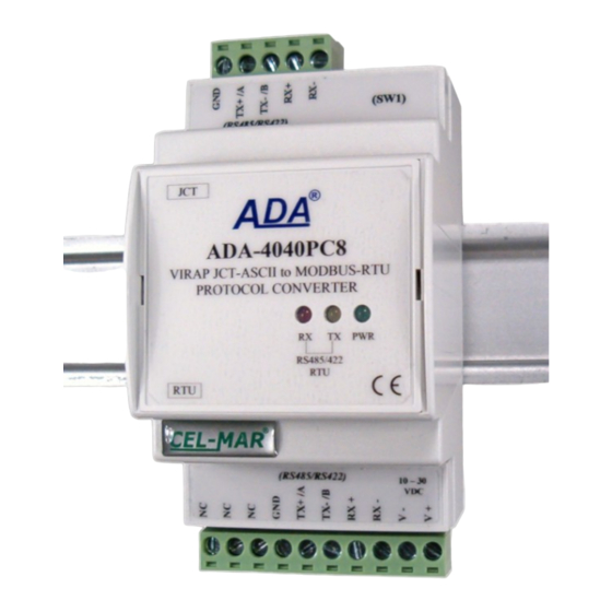
- Page 1 ADA-4040PC8 User manual ADA-4040PC8 VIRAP* JCT-ASCII to MODBUS-RTU Protocol Converter © Copyright 2001-2021 CEL-MAR io_ada-4040pc8_v1.02_en...
-
Page 2: Table Of Contents
ADA-4040PC8 Contents 1. GENERAL INFORMATION..................................3 1.1. WARRANTED INFORMATION............................... 3 1.2. GENERAL CONDITIONS FOR SAFE USE............................ 3 1.3. CE LABEL....................................... 3 1.4. ENVIRONMENTAL PRESERVATION............................. 3 1.5. SERVICE AND MAINTENANCE..............................3 1.6. PACK CONTENTS..................................3 2. PRODUCT INFORMATION..................................3 2.1. PROPERTIES....................................3 2.2. -
Page 3: General Information
1.1. WARRANTED INFORMATION ADA-4040PC8 converter is covered by a two year warranty from date of sale. In case of being damaged it will be repair or the damaged component will be replace. The warranty does not cover damage caused from improper use, materials consumption or any unauthorized changes. -
Page 4: Description
230.4 kbps through two or one pair of twisted pairs connected to screw terminals. The device for its operation uses the lines RX +, RX-, TX + / A, TX- / B led to the terminal strips. Up to 32 ADA-4040PC8 devices operating in half duplex mode can be connected to the RS485 / RS422 bus. -
Page 5: Isolation
- not supply converter from power circuit device that generates large impulse interference such as transmitters, contactors. 3.1. ASSEMBLING Casing of ADA-4040PC8 is adapted it assembly he TS-35 (DIN35) rail. It install the converter, should ugh mounted he the rail upper part of the cover then press bottom part it hear characteristic "Click" sound. -
Page 6: Connection Of Jct1 Controller To Rs485 (4W) Modbus-Rtu Bus
9600Bd/8/N/1 Controller Controller VIRAP JCT VIRAP JCT Fig 5. Example connection of ADA-4040PC8 to RS485 (4W) 4-wires bus and JCT1 controller to ADA-4040PC8 3.3.2. CONNECTION OF JCT1 CONTROLLER TO RS485 (2W) MODBUS-RTU BUS RS485(2W) BUS RS485 / RS422 19200Bd/8/N/1 connector... -
Page 7: Gnd Terminals Connection
3.4. POWER SUPPLY CONNECTION We recommend for powering of ADA-4040PC8 to use individual, stabilized power supply with output voltage from 10 V= to 30V=, min. nominal power 2W, e.g. HDR-15-24. Power cable from DC power supplies to device can not be longer than 3m. Should connect positive (+) end of DC power supplies to V+ device terminal and negative (-) end to V- on terminal block. -
Page 8: Configuration By Using Adaconfig
5.2. CONFIGURATION BY USING ADACONFIG The configuration of ADA-4040PC8 converter can be made by the use of ADAConfig Software - selling with converter. To make the configuration, connect converter to computer (see pt. 3.2) and power supply. If after power, on the front panel is not lit green LED PWR, check the power connection (polarity). -
Page 9: Firmware Update
ADA-4040PC8 Fig. 7. View of ADAConfig software interface 5.3. FIRMWARE UPDATE Set SW1 micro switch to configuration mode as in table below. SW1-1 SW1-2 In the configuration mode the yellow LED will blink with frequency 1Hz. Press a button [Load New Firmware] [8] to change the software delivered by manufacturer. -
Page 10: Emergency Firmware Update
To check those counters press the button [Read transmission errors], and to delete (zeroing of counters in the memory of the converter) press [Delete transmission errors]. In case of parity errors or frame errors, should be checked the ADA-4040PC8 converter's configuration and correctness connection of RS485 bus to RTU and JCT converter ports. -
Page 11: Operation
ADA-4040PC8 7. OPERATION ADA-4040PC8 is a bidirectional converter of JCT-ASCII protocol to MODBUS-RTU protocol, with the possibility of converting the baud rate, data format (number of data bits, parity bit, stop bits) and the type of RS485 interface to RS422. -
Page 12: Implementation Of The Modbus-Rtu Protocol
8. IMPLEMENTATION OF THE MODBUS-RTU PROTOCOL ADA-4040PC8 protocol converter allows connecting controllers with the JCT-ASCII protocol as SLAVE to the RS485 bus MODBUS- RTU. The length of RS485 bus can be extended (next segments of 1200 m) by the use of ADA-4040 repeaters or ADA-4044H HUBs RS485. -
Page 13: Frame Structure Of Modbus-Rtu Protocol
8.3.1. 0x03/0x04 FUNCTION - READING OF THE 16-BITS VALUE OF REGISTERS [4X/3X- REFERENCES] Function 0x03 / 0x04 are used for readout the registers from ADA-4040PC8, in which are available measurement values and status values of JCT controller. The measurement values readout form MODBUS-RTU register is presented by a 16-bit register. -
Page 14: 0X06 Function - Save Values To 16-Bits Register [4 X-References]
MODBUS registers are in the format of the 16-bits integral number with the character (in C/C++ type short int). The value saved in the MODBUS register of ADA-4040PC8, is obtained by multiplying real measurement value by the DW factor, according to the following algorithm. -
Page 15: Exceptions Of The Modbus-Rtu Protocol
1- Byte - - - CRC-Hi 1- Byte - - - 8.4. EXCEPTIONS OF THE MODBUS-RTU PROTOCOL ADA-4040PC8 in case of received MODBUS-RTU frame, includes: - unsupported function, - unknown data address, - unknown data value - or when JCT controller not respond on inquiries returns to MASTER type device the frame containing the appropriate exception –... -
Page 16: Versions
ADA-4040PC8 9. VERSIONS ADA-4040PC8 - Version: Order example: Standard Product Symbol: ADA-4040PC8-1-23 1 – standard version , 3-way galvanic isolation: 23 - 1 kV =, 3-way galvanic isolation, 1 kV = 3 kV = 10. SPECIFICATION TECHNICAL DATE Transition Parameters... - Page 17 Thank you for purchasing CEL-MAR Company products. We hope that this user manual helped connect and start up the ADA-4040PC8 converter. We also wish to inform you that we are a manufacturer of the widest selections of data communications products in the world such as: data transmission converters with interface RS232, RS485, RS422, USB, Current Loop, Fibre-Optic Converters and Ethernet or Wi-Fi.
Need help?
Do you have a question about the ADA-4040PC8 and is the answer not in the manual?
Questions and answers