
Related Manuals for CEL-MAR ADA-4040PC1


Summary of Contents for CEL-MAR ADA-4040PC1
- Page 1 ADA-4040PC1 User manual ADA-4040PC1 MODBUS-ASCII to MODBUS-RTU converter Copyright © 2001-2017 CEL-MAR sp.j. io_ada-4040pc1_v1.03_en...
-
Page 2: Table Of Contents
ADA-4040PC1 Contents 1. GENERAL INFORMATION..................................3 1.1. WARRANTED INFORMATION............................... 3 1.2. GENERAL CONDITIONS FOR SAFE USE............................ 3 1.3. CE LABEL....................................... 3 1.4. ENVIRONMENTAL PRESERVATION............................3 1.5. SERVICE AND MAINTENANCE..............................3 1.6. PACK CONTENTS..................................3 2. PRODUCT INFORMATION..................................3 2.1. PROPERTIES....................................3 2.2. -
Page 3: General Information
1.1. WARRANTED INFORMATION ADA-4040PC1 converter is covered by a two year warranty from date of sale. In case of being damaged it will be repair or the damaged component will be replace. The warranty does not cover damage caused from improper use, materials consumption or any unauthorized changes. -
Page 4: Description
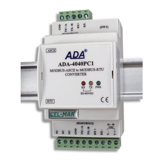
The converter use RX+, RX-, TX+/A, TX-/B lines for functioning. It is possible to connect 32 devises to RS485/RS422 network constructed on base of ADA-4040PC1, working at the half duplex or full duplex mode. Over-voltage protection on each RS485/RS422 line was made on base of 600W over-voltage led and fuses. -
Page 5: Isolation
- not supply converter from power circuit device that generates large impulse interference such as transmitters, contactors. 3.1. ASSEMBLING The cover of ADA-4040PC1 converter is adapted to assembly on TS-35 (DIN35) rail. To install the converter, should be mounted on the rail upper part of the cover then press bottom part to hear characteristic „Click” sound. -
Page 6: Rs485 Network Connection
Fig 5. 2-Wire connecting ADA-4040PC1 to PC with the use of ADA-I9140 USB to RS485/RS422 3.3. RS485 NETWORK CONNECTION RS485/RS422 interface in ADA-4040PC1 converter is described as: Tx+/A, Tx-/B, Rx+, Rx-. Connection of ADA-4040PC1 to RS485(4W) and RS485(2W) network are shown bellow. -
Page 7: Rs485(2W) Bus Connection
2W, e.g. ZS-12/250. Power cable from DC power supplies to device can not be longer than 3m. Should connect positive (+) end of DC power supplies to V+ device terminal and negative (-) end to V- on terminal block. ADA-4040PC1 has protection against power supply reverse connection. -
Page 8: Description Of Signalling Leds
5.2. CONFIGURATION BY USING ADACONFIG The configuration of ADA-4040PC1 converter can be made by the use of ADAConfig Software - selling with converter. To make the configuration, connect converter to computer (see pt. 3.2) and power supply. If after power, on the front panel is not lit green LED PWR, check the power connection (polarity). -
Page 9: Firmware Update
ADA-4040PC1 Fig. 8. View of ADAConfig software interface 5.3. FIRMWARE UPDATE Set SW1 micro switch to configuration mode as in table below. SW1-1 SW1-2 In the configuration mode the yellow LED will blink with frequency 1Hz. Press a button [Load New Firmware] to change the software delivered by manufacturer. -
Page 10: Emergency Firmware Update
SW1-2 After microswitch setting, should be restarted ADA-4040PC1, by turning OFF and then ON the power supply. The yellow LED will light continuously and the converter will be in Emergency Firmware Update mode. Now follow the description in the above point. -
Page 11: Data Transmission Diagnostics
ADA-4040PC1 In case of faulty functioning ADA-4040PC1, can be restored the factory default setting of the converter internal registers. Set SW1 microswitch mode as in the table below. SW1-1 SW1-2 Disconnect the power and after while connect again the power. After that, will be loaded the factory default setting to the converter internal registers. -
Page 12: Versions
ADA-4040PC1 Fig. 10. Connection of MODBUS-ASCII devices to RS485 MODBUS-RTU bus 8. VERSIONS ADA-4040PC1 - Version: Order example: Standard Product Symbol: ADA-4040PC1-1-23 1 – standard version, 3-way galvanic isolation: 23 – 1kV=, 3-way galvanic isolation, 1kV= 3kV= 9. SPECIFICATION TECHNICAL DATA... - Page 13 ADA-4040PC1 • PWR – green LED power supply, • RX - red LED data receiving from RTU port – RS485/RS422, Optical signalisation • TX - yellow LED data transmission through RTU port – RS485/RS422. Electrical Parameters Power requirements 10 - 24 – 30 V DC Power Cable Recommended length of power cable –...
- Page 14 ADA-4040PC1...
- Page 15 ADA-4040PC1...
- Page 16 Thank you for purchasing CEL-MAR Company products. We hope that this user manual helped connect and start up the ADA-4040PC1 converter. We also wish to inform you that we are a manufacturer of the widest selections of data communications products in the world such as: data transmission converters with interface RS232, RS485, RS422, USB, Current Loop, Fibre-Optic Converters and Ethernet or Wi-Fi.
Need help?
Do you have a question about the ADA-4040PC1 and is the answer not in the manual?
Questions and answers