Sign In
Upload
Manuals
Brands
Beckhoff Manuals
Touch terminals
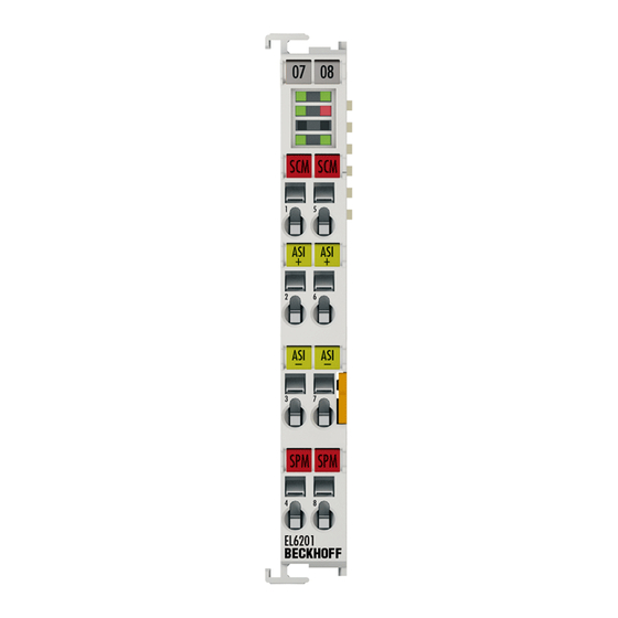
EL6201
Beckhoff EL6201 Manuals
Manuals and User Guides for Beckhoff EL6201. We have
1
Beckhoff EL6201 manual available for free PDF download: Documentation
Beckhoff EL6201 Documentation (233 pages)
AS-Interface Master Terminal
Brand:
Beckhoff
| Category:
Touch terminals
| Size: 7 MB
Table of Contents
Table of Contents
3
1 Foreword
5
Notes on the Documentation
5
Safety Instructions
6
Documentation Issue Status
7
Version Identification of Ethercat Devices
7
Fig. 1 EL5021 el Terminal, Standard IP20 IO Device with Batch Number and Revision ID (Since 2014/01)
9
Fig. 2 EK1100 Ethercat Coupler, Standard IP20 IO Device with Batch Number
9
Fig. 3 CU2016 Switch with Batch Number
10
Fig. 4 EL3202-0020 with Batch Numbers 26131006 and Unique ID-Number 204418
10
Fig. 5 EP1258-00001 IP67 Ethercat Box with Batch Number 22090101 and Unique Serial Number 158102
10
Fig. 6 EP1908-0002 IP76 Ethercat Safety Box with Batch Number 071201FF and Unique Serial Number 00346070
10
Fig. 7 EL2904 IP20 Safety Terminal with Batch Number/Date Code 50110302 and Unique Serial Num- Ber 00331701
11
Fig. 8 ELM3604-0002 Terminal with ID Number (QR Code) 100001051 and Unique Serial Number 44160201
11
2 Product Overview
12
Introduction
12
Fig. 10 AS-I Logo
12
Technical Data
13
Technology
14
AS-I Requirements
14
Assembly Using the Piercing Technology
14
Fig. 11 AS-I Logo
14
Fig. 12 Profiled Twin-Core Cable for Use with the AS-I Technology
15
Fig. 13 Upper and Lower Half of the AS-I Component Are Disassembled
15
Fig. 14 the AS-I Cable Is Placed - Always Without Error Thanks to Its Profiling - in the Lower Half of the AS-I Component
15
Fig. 15 Upper and Lower Halves Are Assembled Using a Simple Tool
15
Fig. 16 Finished Assembled Junction
15
AS Interface for Every Topology
16
Start
16
Fig. 17 the Piercing Technology Ensures the Reliable Connection of the AS-I Component to the AS-I Network Cable
16
3 Basics Communication
17
Ethercat Basics
17
Ethercat Cabling - Wire-Bound
17
General Notes for Setting the Watchdog
18
Fig. 18 System Manager Current Calculation
18
Fig. 19 Ethercat Tab -> Advanced Settings -> Behavior -> Watchdog
19
Ethercat State Machine
20
Fig. 20 States of the Ethercat State Machine
21
Coe Interface
22
Fig. 21 "Coe Online " Tab
23
Fig. 22 Startup List in the Twincat System Manager
24
Fig. 23 Offline List
25
Fig. 24 Online List
26
4 Installation
27
Instructions for ESD Protection
27
Installation on Mounting Rails
27
Fig. 25 Spring Contacts of the Beckhoff I/O Components
27
Fig. 26 Attaching on Mounting Rail
28
Fig. 27 Disassembling of Terminal
29
Installation Instructions for Enhanced Mechanical Load Capacity
30
Fig. 28 Power Contact on Left Side
30
Connection System
31
Fig. 29 Standard Wiring
31
Fig. 30 Pluggable Wiring
32
Fig. 31 High Density Terminals
33
Fig. 32 Mounting a Cable on a Terminal Connection
33
Prescribed Installation Position
34
Fig. 33 Recommended Minimum Distances for Standard Installation Position
34
Mounting of Passive Terminals
35
Fig. 34 Correct Configuration
35
Fig. 35 Incorrect Configuration
35
Leds and Connection
36
Fig. 36 EL6201 Leds
36
Fig. 9 EL6201
37
Fig. 37 Connection of EL6201 AS-I Master
37
Fig. 38 Connection AS-I Potential Supply Terminal EL9520
38
5 Commissioning
40
Twincat Quick Start
40
Twincat 2
64
Twincat 3
64
Twincat Development Environment
64
Installation of the Twincat Real-Time Driver
64
Notes Regarding ESI Device Description
70
Twincat ESI Updater
74
Distinction between Online and Offline
74
OFFLINE Configuration Creation
75
ONLINE Configuration Creation
80
Ethercat Subscriber Configuration
88
Fig. 128 "Process Data" Tab
90
Fig. 129 Configuring the Process Data
91
Fig. 130 „Startup" Tab
92
Fig. 131 "Coe - Online" Tab
93
Fig. 132 Dialog "Advanced Settings
94
Fig. 133 „Online" Tab
95
Fig. 134 "DC" Tab (Distributed Clocks)
96
General Notes - Ethercat Slave Application
98
Fig. 135 Selection of the Diagnostic Information of an Ethercat Slave
98
Fig. 136 Basic Ethercat Slave Diagnosis in the PLC
99
Fig. 137 EL3102, Coe Directory
101
Fig. 138 Example of Commissioning Aid for a EL3204
102
Fig. 139 Default Behaviour of the System Manager
103
Fig. 140 Default Target State in the Slave
103
Fig. 141 PLC Function Blocks
104
Fig. 142 Illegally Exceeding the E-Bus Current
105
Fig. 143 Warning Message for Exceeding E-Bus Current
105
Functionality of the AS-I Master
106
AS-I Status Machine
106
Fig. 144 Status Machine Overview
106
Lists
107
Operating Modes
107
Fig. 145 Lists of the AS-I Slaves in Configuration and Protected Mode
107
Operating Phases
108
Address Assignment of the AS-I Slaves
109
Automatic Address Assignment
109
Quickstart
109
Fig. 146 Maximum Topology Extent with Standard AS-I Power Supply and AS-I Power24 Supply
111
Fig. 147 Wiring Diagram AS-I Slave / EL6201
112
Fig. 148 Configuration Tree in the Twincat System Manager
113
Fig. 149 AS-I System Overview with the Slaves to be Addressed
114
Fig. 150 Address Assignment for the AS-I Slave
114
Fig. 151 Address Assignment for the AS-I Slave Accepted
115
Fig. 152 Switching to "Protected Mode" and Completion of Project Planning
115
Fig. 153 Activating "Auto Programming Mode
116
Fig. 154 no Slave Detected in the AS-I System Overview
117
Fig. 155 the First Slave Connected Is Allocated Address "1A
117
Fig. 156 the Second Slave Connected Is Allocated Address "2A
118
Fig. 157 Undefined State of the Slave to be Projected
119
Fig. 158 Remedy: Activating AS-I Data Exchange
119
Fig. 159 the Third Connected Slave Is Allocated Address "3A"; Switching to "AS-I Protected Mode"; Con- Firming the Configuration
120
Fig. 160 Failure of Slave "2A", Marked Red
121
Fig. 161 All Slaves Are Shown Without Configuration Details. Detected, Projected and Active Slaves Are Marked Green
121
Fig. 162 Detected and Projected Slaves Shown Without Details
122
Fig. 163 Detected and Projected Slaves Shown with Details
122
Fig. 164 Profiles of Detected and Projected Slaves Shown with Details
123
Fig. 165 Process Data of Detected and Projected Slaves Shown with Details
123
Further Notes on Commissioning
124
Fig. 166 Properties Window with Further Information
124
Fig. 167 Left Part of the Settings Tab
125
Fig. 168 AS-I Master View
125
Fig. 169 Option Menu "Project All Detected Slaves
126
Fig. 170 Manual Programming
127
Fig. 171 Storing the Startup Data
127
Object Description and Parameterization
130
Restore Object
130
Configuration Data
130
Command Object
134
Input Data
137
Output Data
137
Information Data
137
Diagnostic Data
138
ASI Data
141
Object Description - Standard Objects
145
6 Appendix
216
Ethercat al Status Codes
216
Firmware Compatibility
216
Firmware Update El/Es/Em/Epxxxx
216
Restoring the Delivery State
227
Support and Service
228
List of Illustrations
229
Advertisement
Advertisement
Related Products
Beckhoff TwinSAFE EL6910
Beckhoff EtherCAT EL6752
Beckhoff EL6601
Beckhoff EL6614
Beckhoff EL6751
Beckhoff EL6652-00 0 Series
Beckhoff EL6652-0010
Beckhoff EL6731
Beckhoff EL6692
Beckhoff EL6900
Beckhoff Categories
Touch terminals
Industrial PC
Control Unit
Industrial Equipment
Power Supply
More Beckhoff Manuals
Login
Sign In
OR
Sign in with Facebook
Sign in with Google
Upload manual
Upload from disk
Upload from URL