Falcon Classic 110 Gas User's Manual & Installation Instructions
Hide thumbs
Also See for Classic 110 Gas:
- User manual (39 pages) ,
- User manual (32 pages) ,
- User's manual & installation instructions (48 pages)
Table of Contents
Advertisement
Advertisement
Table of Contents

Related Manuals for Falcon Classic 110 Gas


Summary of Contents for Falcon Classic 110 Gas
- Page 1 USER GUIDE & INSTALLATION INSTRUCTIONS Classic 110 Gas Australia U110809-01B...
-
Page 3: Table Of Contents
Contents Before You Start... Installation Personal Safety Service and Spares Gas Connection Safety If You Have a Problem If You Smell Gas Please Note Peculiar Smells Out of Warranty Ventilation Spare Parts Maintenance Safety Requirements and Regulations Oven Care Provision of Ventilation Grill/Glide-out Grill™... -
Page 5: Before You Start
Before You Start... • DO NOT use a steam cleaner on your cooker. Your cooker should give you many years of trouble-free cooking if installed and operated correctly. It is important • Always keep combustible materials, e.g. curtains, and that you read this section before you start. flammable liquids a safe distance away from the cooker. -
Page 6: Peculiar Smells
Peculiar Smells Maintenance • Only a qualified service engineer should service the When you first use your cooker it may give off an odour. This should stop after use. appliance and only approved spare parts should be used. It is recommended that this appliance is serviced Before using for the first time, make sure that all packing annually. -
Page 7: Oven Care
a flaming pan on a surface unit by covering the pan Fig. 1.1 completely with a well fitting lid or baking tray. If available, use a multi-purpose dry chemical or foam- type fire extinguisher. • DO NOT modify this appliance. This appliance is not intended to be operated by means of external timer or separated remote-control system. -
Page 8: Grill/Glide-Out Grill™ Care
Grill/Glide-out Grill™ Care Cleaning • When using the grill, make sure that the grill pan is • Isolate the electricity supply before carrying out any in position and pushed fully in, otherwise the control thorough cleaning. Allow the cooker to cool. knobs may become very hot. -
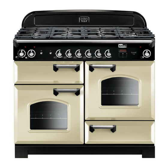
Page 9: Cooker Overview
Cooker Overview Fig. 2.1 The 110 gas cooker (Fig. 2.1) has the following features: Fig. 2.2 A. 5 hotplate burners including a wok burner and warmer B. A control panel C. A grill D. Left-hand oven E. Right-hand oven F. A storage drawer Hotplate Burners The drawing by each of the central knobs indicates which burner that knob controls. -
Page 10: Wok Burner
The igniter should spark and light the gas. Keep holding the Fig. 2.3 knob pressed in to let the gas through to the burner for about ten seconds. If, when you let go of the control knob, the burner goes out, then the FSD has not been bypassed. -
Page 11: The Wok Cradle (Optional Extra)
The Wok Cradle (optional extra) Fig. 2.9 The wok cradle is designed to fit a 35 cm wok. If you use a different wok, make sure that it fits the cradle. Woks vary very widely in size and shape. It is important that the wok sits down on the pan support –... -
Page 12: The Grill
The Grill Fig. 2.15 CAUTION: This appliance is for cooking purposes only. It must not be used for other purposes, for example room heating. CAUTION: Accessible parts may be hot when the grill is in use. Young children should be kept away. Open the door and, using the handle, pull the grill pan forward (Fig. -
Page 13: The Ovens
The Ovens ArtNo.323-0003 Bray gas oven burner flame Fig. 2.19 The clock must be set to the time of day before the ovens will work. See the following section on ‘The Clock’ for instructions on setting the time of day. References to ‘left-hand’... -
Page 14: Operating The Ovens
Cover dishes tightly with a lid or foil to prevent evaporation Meat Temperature and transfer of flavour. Beef Rare 60 °C / 140 °F Once the oven has been loaded and the ‘S’ setting is in Medium 71 °C / 160 °F operation resist the temptation to open the oven door. -
Page 15: Accessories
Accessories Fig. 2.25 Oven Shelves Shelf guard The cooker is supplied with 4 flat shelves (Fig. 2.25). The oven shelves can be easily removed and refitted. Pull the shelf forward until the back of the shelf is stopped by the shelf stop bumps in the oven sides (Fig. 2.26). Front Lift up the front of the shelf so the back of the shelf will pass under the shelf stop and then pull the shelf forward... -
Page 16: Button Clock
3 Button clock Using the clock Fig. 3.1 You can use the clock to turn the programmable oven on and off. The clock must be set to the time of day before the oven will work. NOTE: When using the timer functions, first set the clock as ArtNo.306-0001 - 3-button clock required before setting the oven temperature. - Page 17 When the ‘stop time’ is reached an alarm will sound and Fig. 3.7 the oven will stop working. The word ‘AUTO’ will flash on the display (Fig. 3.6). Press any button to stop the alarm and return to manual cooking. If the alarm is not stopped, it will stop ArtNo.306-0001 - 3-button clock automatically after 7 minutes.
-
Page 18: Cooking Tips
Cooking Tips Tips on cooking with the timer General oven tips If you want to cook more than one dish, choose dishes that The wire shelves should always be pushed firmly to the back require approximately the same cooking time. However, of the oven. -
Page 19: Cooking Table
Cooking Table The oven control settings and cooking times given in the table below are intended to be used as a guide only. Individual tastes may require the temperature to be altered to provide a preferred result. ArtNo.050-0019 - Albertine SC - Shelf position Food is cooked at lower temperature in a fan oven than in a conventional oven. -
Page 20: Cleaning Your Cooker
Cleaning your cooker Essential Information Fig.6.1 Isolate the electricity supply before carrying out any thorough cleaning. Allow the cooker to cool. NEVER use paint solvents, washing soda, caustic cleaners, biological powders, bleach, chlorine based bleach cleaners, coarse abrasives or salt. DO NOT mix different cleaning products –... -
Page 21: Glide-Out Grill
Glide-out Grill Fig.6.5 Before you remove any of the grill parts for cleaning. make sure that they are cool, or use oven gloves. DO NOT use any abrasive substances. The face of the grill burner will darken with use – this is perfectly normal. -
Page 22: Ovens
NOTE: The oven doors are triple glazed, the inner two panels Fig.6.11 Thermostat temperature sensor are fixed together and should not be separated. After cleaning, carefully refit the outer door panel and replace the side fixing screws. DO NOT use harsh abrasive cleaners or sharp metal scrapers to clean the oven door glass since they can scratch the surface, which may result in shattering of the glass. - Page 23 Cleaning Table Cleaners listed (Table 6.1) are available from supermarkets or electrical retailers as stated. For enamelled surfaces use a cleaner that is approved for use on vitreous enamel. Regular cleaning is recommended. For easier cleaning, wipe up any spillages immediately. Hotplate Part Finish...
-
Page 24: Troubleshooting
Troubleshooting What cleaning materials are recommended for the The knobs get hot when I use the oven or the grill. Can I cooker? avoid this? See the ‘Cleaning’ section for recommended cleaning Yes, this is caused by heat rising from the oven or the grill, materials. - Page 25 Oven not coming on Fig. 7.1 Is the power on? Is the clock illuminated? If not, there may be something wrong with the power supply. Is the cooker supply on at the isolator switch? ArtNo.324-0005 Oven light bulb Has the time of day been set? The timed oven is not coming on when automatic cooking Has the oven knob been left in the ‘OFF’...
-
Page 26: Installation
INSTALLATION Check the appliance is gas sound when you have finished. Installation Service and Spares Firstly, please complete the appliance details below and keep them safe for future reference – this information will enable us to accurately identify the particular appliance and help us to help you. Filling this in now will save time and inconvenience if you later have a problem with the appliance. -
Page 27: Safety Requirements And Regulations
INSTALLATION Check the appliance is gas sound when you have finished. Safety Requirements and Provision of Ventilation Regulations This appliance is not connected to a combustion products evacuation device. Particular attention shall be given to the Please read the Before you start... chapter, before relevant requirements regarding ventilation in accordance you begin any installation and maintenance work on with AS/NZS 5601. - Page 28 INSTALLATION Check the appliance is gas sound when you have finished. You will need the following equipment to complete the Checking the Parts: cooker installation satisfactorily: Pan supports Plinth • Flexible gas hose. • Gas pressure tester/manometer. • Multimeter: For electrical checks. ArtNo.110-0002 110 pan supports You will also need the following tools: Electric drill...
-
Page 29: Positioning The Cooker
70°C. If this appliance is installed near vinyl wrapped surfaces, use an installation kit available from the vinyl-wrap supplier. Falcon cannot accept any responsibility for damage caused due to installation into cabinets with low temperature tolerances. -
Page 30: Moving The Cooker
INSTALLATION Check the appliance is gas sound when you have finished. Moving the Cooker Fig. 8.3 On no account try and move the cooker while it is plugged into the electricity supply. The cooker is very heavy, so take great care. We recommend that two people manoeuvre the cooker. -
Page 31: Fitting The Stability Bracket And Chain
INSTALLATION Check the appliance is gas sound when you have finished. Fitting the Stability Bracket and Fig. 8.6 Chain A stability bracket and chain MUST be fitted when the cooker is connected to a flexible gas supply. Unless properly installed, the cooker could be tipped by Alternative positions leaning on the door. -
Page 32: Fitting The Oven Burner Trim
INSTALLATION Check the appliance is gas sound when you have finished. Fitting the Oven Burner Trim Fig. 8.10 Oven burner bracket The oven burner has an enamel burner trim. To fit the trim, simply hook it over the front of the oven burner bracket (Fig. -
Page 33: Electrical Connection
INSTALLATION Check the appliance is gas sound when you have finished. Electrical Connection Earth Continuity Check WARNING: THIS COOKER MUST BE EARTHED. The cooker must be disconnected from the power supply. This appliance must be installed by a qualified electrician Using an multimeter or ohmmeter to check the resistance, to comply with with current AS/NZS 3000 Wiring Rules test the leads from any of the cooker’s earth points (e.g. - Page 34 INSTALLATION Check the appliance is gas sound when you have finished. Fixed Wiring Fig. 8.13 Disconnect from the mains supply. For connection to fixed wiring, i.e. flexible conduit, Remove the electrical terminal cover on the back panel (Fig. 8.13). Remove the M4 screw securing the reducer plates to the conduit box (Fig.
-
Page 35: Final Checks
INSTALLATION Check the appliance is gas sound when you have finished. Final Checks Fig. 8.18 Note: The clock must be set before the ovens will work. See ‘The Clock’ section for instructions on setting the time of day. Hotplate Check Check each burner in turn. -
Page 36: Conversion To Lp Gas
WARNING – SERVICING TO BE CARRIED OUT ONLY BY AN AUTHORISED PERSON Disconnect from electricity and gas before servicing. Check appliance is safe when you have finished. Conversion to LP Gas Conversion from Natural Gas (1.0 kPa) Fig. 9.1 to LPG X Propane (2.54 kPa) A suitably competent person must perform the conversion. -
Page 37: Grill
WARNING – SERVICING TO BE CARRIED OUT ONLY BY AN AUTHORISED PERSON Disconnect from electricity and gas before servicing. Check appliance is safe when you have finished. Grill Fig. 9.4 Injector Lift up the spring retaining the grill holder and slide the jet holder out of the burner venturi (Fig. -
Page 38: 10. Servicing
WARNING – SERVICING TO BE CARRIED OUT ONLY BY AN AUTHORISED PERSON Disconnect from electricity before servicing. Check appliance is safe when you have finished. 10. Servicing BEFORE SERVICING ANY GAS CARRYING Fig. 10.1 COMPONENTS TURN OFF THE GAS SUPPLY Check the appliance is gas sound after completion of service. - Page 39 WARNING – SERVICING TO BE CARRIED OUT ONLY BY AN AUTHORISED PERSON Disconnect from electricity before servicing. Check appliance is safe when you have finished. Hotplate 2.4 To Replace a Hotplate Burner Electrode DISCONNECT FROM THE ELECTRICITY SUPPLY. 2.1 To Remove the Hotplate Lift off pan supports and remove the burner cap.
- Page 40 WARNING – SERVICING TO BE CARRIED OUT ONLY BY AN AUTHORISED PERSON Disconnect from electricity before servicing. Check appliance is safe when you have finished. Controls Fig. 10.4 3.1. To Replace the Ignition or Light Switch DISCONNECT FROM THE ELECTRICITY SUPPLY. Remove the control panel (see 1.1).
- Page 41 WARNING – SERVICING TO BE CARRIED OUT ONLY BY AN AUTHORISED PERSON Disconnect from electricity before servicing. Check appliance is safe when you have finished. Grill Spring clip Fig. 10.5 BEFORE SERVICING ANY GAS CARRYING COMPONENTS, TURN OFF THE GAS SUPPLY. 4.1 To Change the Grill Control Tap DISCONNECT FROM THE ELECTRICITY SUPPLY.
- Page 42 WARNING – SERVICING TO BE CARRIED OUT ONLY BY AN AUTHORISED PERSON Disconnect from electricity before servicing. Check appliance is safe when you have finished. Ovens Fig. 10.7 5.1 To Remove an Oven Thermostat DISCONNECT FROM THE ELECTRICITY SUPPLY. Remove the right-hand hotplate tray (see 2.1); for the left- hand oven remove the left-hand side panel (see 1.2).
- Page 43 WARNING – SERVICING TO BE CARRIED OUT ONLY BY AN AUTHORISED PERSON Disconnect from electricity before servicing. Check appliance is safe when you have finished. Check the performance. Fig. 10.9 Fig. 10.10 5.6 To Change the Oven Solenoids DISCONNECT FROM THE ELECTRICITY SUPPLY. Move the cooker forward to gain access to the rear.
- Page 44 WARNING – SERVICING TO BE CARRIED OUT ONLY BY AN AUTHORISED PERSON Disconnect from electricity before servicing. Check appliance is safe when you have finished. 6.3 To Adjust an Oven Door Angle Fig. 10.11 Centreline of hinge pin The bottom hinge of either oven door can be adjusted to alter the angle of the door (Fig.
-
Page 45: 11. Circuit Diagram
11. Circuit Diagram Test For manufacturing switch test purposes only Sensor Sensor Spark Spark The connections shown in the circuit diagram are for single-phase. The ratings are for 230 V 50 Hz. Code Description Code Colour Right-hand oven thermostat switch Blue Left-hand oven thermostat switch Brown... -
Page 46: 12. Technical Data
12. Technical Data ArtNo.105-0008 - Technical data - 90 induction - Elan This cooker is designed for use on Natural Gas, although a conversion for LP (LPG X Propane (2.54 kPa)) gas is packed with the cooker. INSTALLER: Please leave these instructions with the User. DATA BADGE LOCATION: Cooker back, serial number repeater badge below oven door opening. - Page 47 Notes...
- Page 48 Clarence Street, Royal Leamington Spa, Warwickshire, CV31 2AD, England. Tel: +44 (0) 800 804 6261 | +44 (0) 370 789 5107 E-mail: consumers@falconappliances.co.uk...
Need help?
Do you have a question about the Classic 110 Gas and is the answer not in the manual?
Questions and answers