SystemAir Topvex SC Installation Instructions Manual
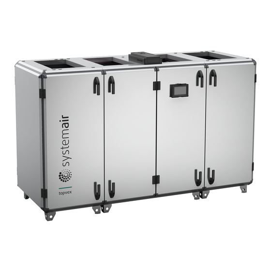
Air handling unit
Hide thumbs
Also See for Topvex SC:
- Operation and maintenance (32 pages) ,
- Operation and maintenance instructions (28 pages) ,
- Operation and maintenance instructions (40 pages)

Subscribe to Our Youtube Channel
Related Manuals for SystemAir Topvex SC


Summary of Contents for SystemAir Topvex SC
- Page 1 Air Handling Unit Topvex SC, TC Installation instructions Document in original language | 214958 · A002...
- Page 2 © Copyright Systemair AB All rights reserved E&OE Systemair AB reserves the rights to alter their products without notice. This also applies to products already ordered, as long as it does not affect the previously agreed specifications. 214958 | A002...
-
Page 3: Table Of Contents
Lifting unit with forklift truck .....3 16 Disposal ............40 Using lifting frame ........4 Transport and storage ........5 Storage ..........5 Unpacking .............5 Duct connections..........6 Topvex SC..........6 Topvex TC..........6 Internal components ........7 Topvex SC..........7 Topvex TC..........8 Installation.............9 Requirements for installation ....10 Disassembly size SC 60-70, TC 60- 70............. -
Page 5: Product Information
Product information | Product information This manual includes the information required for installing the heat recovery unit type Topvex SC, TC manufactured by Systemair Sverige AB. The units include the following model options: The air handling units is delivered with airflow control CAV (Constant Air Volume). -
Page 6: Overview
The heat recovery units are intended to provide ventilation and depending on settings, heat recovery, air heating or free cooling. Topvex SC, TC are meant for indoor installation. Sound levels exceeding 70 dB(A) may occur depending on model and size (see online catalogue at www.systemair. com for detailed information). -
Page 7: Unloading From Trailer
Unloading from trailer | Unloading from trailer Warning • The unit is heavy. Be careful during transport and installation. Risk of injury through pinching. Use protective clothing. • Observe the centre of gravity during transportation. The air handling unit is fixed on a pallet. Topvex SC60, Topvex SC70, Topvex TC60, Topvex TC70, are delivered fixed on pallet in sections and secured with a packing belt. -
Page 8: Using Lifting Frame
| Unloading from trailer Using lifting frame Warning • Secure the lifting cable on the tubes. • Do not compress the air handling unit's chassi with the cables. Use a lifting frame connected to pipes in the air handling unit's feet. For size Topvex SC20-Topvex SC35, Topvex TC20–Topvex TC35, place the lifting tubes in the outer feet of the air han- dling unit. -
Page 9: Transport And Storage
Transport and storage | Transport and storage Danger Do not loosen packing belt until the air handling unit is on location for installation! Storage Store the unit covered from dust, rain and snow. Keep duct connections covered during storage and installation. Unpacking Remove the plastic covering the air handling unit. -
Page 10: Duct Connections
| Duct connections Duct connections Left (L) and Right (R) indicate the position of the supply air intake when viewed from access side. Supply air Extract air Exhaust air Outdoor air Topvex SC Topvex TC 214958 | A002... -
Page 11: Internal Components
Internal components | Internal components Topvex SC Fig. 1 Left hand unit Supply air Exhaust air Outdoor air Extract air Description Position Fan supply air Fan extract air Filter supply air Filter extract air Heat exchanger Access control cabinet Damper by-pass outdoor air/Section defrosting (only units with section defrosting) -
Page 12: Topvex Tc
| Internal components Topvex TC Fig. 2 Left hand unit Supply air Exhaust air Outdoor air Extract air Description Position Fan supply air Fan extract air Filter supply air Filter extract air Heat exchanger Access control cabinet Damper by-pass outdoor air/Section defrosting (only units with section defrosting) Control box for section defrosting (only for unit with section defrosting) Internal electrical cabinet Heating coil (EL or HWH/HWL) -
Page 13: Installation
Installation | Installation Topvex SC, TC are meant for indoor installation. Place the unit preferably in a separate room (e.g. storage, laundry room, attic or similar). Verify that all ordered equipment are delivered before starting the installation. Report any deviation from the ordered equipment to the supplier of the Systemair products. -
Page 14: Requirements For Installation
| Installation Requirements for installation Warning • The unit is heavy. Be careful during transport and installation. Risk of injury through pinching. Use protective clothing. • Connect the ducts or provide with protection to prevent access to the fans through the duct connections. Location for installation •... -
Page 15: Disassembly Size Sc 60-70, Tc 60- 70
Installation | Disassembly size SC 60-70, TC 60-70 Disassemble the middle section for transport through smaller openings (min 900 mm). Heaviest part is the heat exchanger: 48 kg x 2. Table 2 Tools required Allen key, 8 mm (5/16"), torx 20, screwdriver, drive pin punch Warning More than one person is needed to disassembly safely. - Page 16 | Installation Remove damper Warning Beware of sharp edges. Use gloves and protective clothing. 4. Loosen the bolts holding the damper rails. Remove the damper rails. 5. Rotate the damper and lift in the direction away from the exchanger. 6. Lift the damper out from the middle section. Caution Do not drag the damper on the exchanger.
- Page 17 Installation | Remove middle door beams 8. Loosen the screws on the door beams (6 screws on front and 6 screws on the back) and remove the beams. Remove the roof 9. Remove the cabling from the roof part. 10.Loosen and remove the 8 screws for the roof's outer beams. 11.Remove the roof.
- Page 18 | Installation Remove the beams 13.Loosen and remove the 8 screws for the floor on the outer beams. 14.Loosen and remove the 8 screws on the reinforcement struts. 214958 | A002...
- Page 19 Installation | 15.Remove the beams. 16.Possible to disassembly the beams further. Remove the heat exchanger Caution • Handle the heat exchanger with care. • The heat exchanger is heavy. 17.Remove the heat exchanger and bypass. 214958 | A002...
-
Page 20: Assembly Of Topvex Sc60, Topvex Sc70
| Installation Assembly of Topvex SC60, Topvex SC70 Attach the heat exchanger Caution • Handle the heat exchanger with care. • The heat exchanger is heavy. 1. Carefully place the heat exchanger and bypass on the bottom plate. Fasten the beams 2. - Page 21 Installation | 3. Fasten the floor’s 8 screws on the outer beams. Fasten the roof Warning The roof part is bulky, two person is needed. 4. Fasten the roof's outer beams with 8 screws. 5. Fasten the cabling to the roof. 214958 | A002...
- Page 22 | Installation Fasten the door beams 6. Fasten the door beams (6 screws on front and 6 screws on the back). Fasten the rail holding the partition wall 7. Fasten the bolts holding the rail on the opposite side of the partition wall. 214958 | A002...
- Page 23 Installation | Fasten the damper 8. Insert the damper in the area above the exchanger. Caution Do not drag the damper on the exchanger. 9. Lift the damper with the short end on the rail at the outer beams. Observe the small hooks to secure the damper. 10.Fasten the damper by fastening the damper rails with the bolts.
- Page 24 | Installation 13.Unite the parts of the air handling unit using a pallet lift. 14.Open the middle doors and section doors. 15.Remove the filters for easy access. 16.Use an allen key on the side of the 8 connectors, to lock the unit's sections. Fig.
- Page 25 Installation | 17.From the inside, attach the quick connection cables between the sides and middle section, figure 6. Cables are marked to facilitate correct connections. Note: Observe the cable markings. Fig. 6 Quick connection, image shows only one cable 214958 | A002...
-
Page 26: Connect The Condensation Drain
| Installation Connect the condensation drain Connect the drainage pipe and drain trap on the exhaust air side at the bottom of the unit, figure 7. Cut the drainage pipe to required height, see table 3. Note: When installed in a non heated place the drain pipe and trap needs to be insulated well to prevent the water from freezing. -
Page 27: Mount The Supply Air Sensor
Installation | Mount the supply air sensor Mount the supply air sensor in the supply air duct. Connect the supply air sensor to the control unit CU27-C located in the Access control cabinet. Connect according to below table. All other temperature sensors are built in to the unit from factory. CU27-C TG-KH/PT1000 Duct sensor T81: UI1... -
Page 28: Electrical Connections
| Electrical connections Electrical connections Separate connection to mains power supply is required to the internal electrical cabinet and to the electric heating coil. Danger • Disconnect the mains power supply to the unit before performing any maintenance or electrical work! •... -
Page 29: Connect Power Supply To Electric Heating Coil
Electrical connections | 10.2 Connect power supply to electric heating coil Open the hatch to the electric heating coil by loosening the four screws. Lead the cable through the cable grommet (1) and connect the mains power supply to the terminals for the electric heating coil (2), figure 11. Possible to reset fuse and overheat protection for the electric heating coil without opening the hatch to the compartment. -
Page 30: Connection Of Water Heating Coil
| Connection of water heating coil Connection of water heating coil Caution Take care not to damage the water battery when connecting water pipes to connectors. Remove the cable grommet and connect the water piping to the female threaded connections. Use a spanner to tighten the connection. -
Page 31: Navipad Control Panel
NaviPad control panel | NaviPad control panel NaviPad is not for outdoor mounting. The protection class of the NaviPad control panel is IP54 and permitted tempera- ture is 0-50° C. Communication between the panel and the control unit in Access control cabinet is possible with up to 100 meters of cable. -
Page 32: Dimensions Navipad
| NaviPad control panel 12.2 Dimensions NaviPad NaviPad is the control panel for Systemair's air handling units and contains several selectable languages. c/cD 40,3 59,4 77,5 12.3 Mount NaviPad holder NaviPad control panel including 3 m cable, holder and screws for mounting on air handling unit are enclosed at delivery. -
Page 33: Access Control Cabinet
Use one of the three flanges on the control cabinet to install accessories. If there is a need to change the type of flange on one position, it’s possible to order additional flanges from Systemair. If Access control cabinet is mounted in an ex- posed environment and a higher enclosure class is required, order a flange suitable for cable glands and replace the ex- isting one (3). -
Page 34: Connect Accessories In Control Unit
| Access control cabinet 13.1 Connect accessories in Control unit CU27-C Fig. 15 Fig. 16 214958 | A002... -
Page 35: Cu27-C
Access control cabinet | External accessory connection CU27-C Notes T1:0 Smoke detector (Calactro Dedicated input for smoke detection UG-3-0) T1:+ T14:24V +24V 24V DC Power CO2/Humidity sensor Analog input max. 550mA T14:AI6 0..10V T14:0V 0V DC Power T15:24V +24V 24V DC Power Duct pressure sensor Analog input max. -
Page 36: Additional Equipment
| Additional equipment External accessory connection CU27-C Notes T71:0V 0V DC Power Valve actuator heating Analog output max. 750mA T71:AO1 0..10V T71:24V +24V 24V DC Power T72:0V 0V DC Power Valve actuator cooling Analog output max. 750mA T72:AO2 0..10V T72:24V +24V 24V DC Power T73:0V... -
Page 37: Technical Data
Technical data | Technical data 15.1 Dimensions and weight Topvex SC Dimensions are given in mm. Topvex SC20, Topvex SC25 2000 56.3 øG Model øG Topvex SC20 Topvex SC25 Topvex SC35 2540 214958 | A002... - Page 38 | Technical data Topvex SC60, Topvex SC70 2742 1292 1015 1201 Model Topvex SC60 1074 Topvex SC70 1420 1017 1203 Table 4 Weight Topvex SC Model Weight, kg Topvex SC20 Topvex SC25 Topvex SC35 Topvex SC60 Topvex SC70 214958 | A002...
- Page 39 Technical data | 15.2 Dimensions and weight Topvex TC Topvex TC20 2000 ø313 Topvex TC25 2000 214958 | A002...
- Page 40 | Technical data Topvex TC35 2540 160 400 130 Topvex TC60, Topvex TC70 2742 1292 399 273 1015 1201 Topvex TC60 1074 Topvex TC70 1420 1017 1203 214958 | A002...
- Page 41 Technical data | Table 5 Weight Topvex TC Model Weight, kg Topvex TC20 Topvex TC25 Topvex TC35 Topvex TC60 Topvex TC70 214958 | A002...
- Page 42 Technical data | 214958 | A002...
- Page 43 Technical data | 214958 | A002...
-
Page 44: Disposal
| Disposal Disposal ♦ Ensure material is recycled. Observe national regulations. ♦ The device and the transport packaging are predominantly made from recyclable raw materials. ♦ Disassemble the air handling unit into its components. ♦ Separate the parts according to: •... - Page 45 214958 | A002...
- Page 46 Systemair Sverige AB Industrivägen 3 SE-739 30 Skinnskatteberg, Sweden Phone +46 222 440 00 www.systemair.com...
Need help?
Do you have a question about the Topvex SC and is the answer not in the manual?
Questions and answers