SystemAir Topvex FC Installation,Operation And Maintenance Instruction
Hide thumbs
Also See for Topvex FC:
- Operation and maintenance instructions (36 pages) ,
- Installation instructions manual (12 pages)
Table of Contents
Advertisement
Quick Links
Advertisement
Table of Contents

Related Manuals for SystemAir Topvex FC


Summary of Contents for SystemAir Topvex FC
- Page 1 Installation, Operation and Maintenance instruction Topvex FC...
-
Page 2: Table Of Contents
Table of content 1 Introduction ............1 Flow chart ..........19 7.9.1 To use the flow chart ...... 19 Product description ........1 7.10 Language ..........20 Intended use ..........1 7.10.1 To change the language ....20 Document description........1 7.11 Time settings .......... -
Page 3: Introduction
Supply air sensor is supplied with the product. The product is not applicable for transportation of air that Topvex FC is a air handling unit for suspended ceiling sup- contains explosive, flammable or aggressive media. The plied with bypass defrosting. -
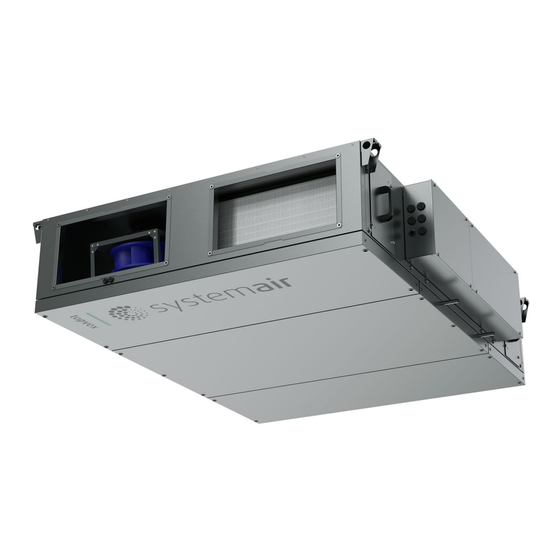
Page 4: Overview Of Supplied Parts
Supply air fan 11. Pressure transmitter (PDT3) for defrosting heat exchanger. Extract air fan 12. Air flow sensor (AFS) only for units with electric heating Filter for supply air coil Filter for extract air 13. Filter hatch handle Heat exchanger 14. -
Page 5: Type Designation
• The product is used together with accessories that are not original accessories from Systemair. Product name Topvex FC Product size Use a mobile device to scan the scannable code and go to the Systemair documentation portal for more documentation and document translations. -
Page 6: Safety
• Always use spare parts from Systemair. • Sound levels exceeding 70 dB(A) may occur depending on model and size. Visit www.systemair.com for more de- tailed information about your product. • The product is not to be used by persons, including chil-... -
Page 7: Safety Labels On The Product
Safety labels on the product Transportation and storage Warning VARNING! WARNING! Make sure that the product does not AVERTISSEMENT! WARNUNG! become damaged or wet during transportation. A damaged or wet Innan anslutningar görs åtkomliga för beröring, måste alla product can cause fire or electric shock. matningskretsar vara brutna. -
Page 8: Installation
Install threaded bars with a dimension of minimum M8 in the ceiling. Threaded bars and nuts are not supplied by Systemair. Make sure that the installation equipment can hold the weight of the product. -
Page 9: To Connect The Product To The Ducts
Install the product with 1-3° lean in the direction to the Systemair recommends to install the ducts together with drainage connections (B). flexible connection DS. Use guide rails to install the flexi- ble connection on the duct joints. -
Page 10: Duct Connection Overview
4.3.1 Duct connection overview To install the supply air To put insulation on the ducts sensor If the product is installed in areas with low outdoor tempera- tures, put insulation on the duct to prevent condensation. If a heater or cooler is used, install the heater or cooler. Make sure that the distance between the supply air sen- Put a minimum of 100 mm insulation on the outdoor air sor and the heater is a minimum of 1.5 m. -
Page 11: Technical Data For Water Heating Coil
Tighten the connections with a spanner. To prevent dam- Note: age of the water heating coil, use a pipe wrench to hold the pipe connections. A frost protection sensor and a venting nipple is installed on the water heating coil. This instruction is only applicable to products supplied with built-in water heating coil. -
Page 12: To Connect The Product To The Power Supply
(A) on the control unit CU27–C2 (B). code on the product name plate, or at www.systemair.com. • Make sure that the cross section of the protective earthing is equal to or larger than the cross section of the phase conductor. -
Page 13: External Accessory Connection
5.4.1 External accessory connection Table 1 Analog inputs CU27-C2 Accessory Notes T1:0 Smoke detector (Calactro UG-3-0) Dedicated input for smoke detection T1:+ T14:24V +24V 24V DC Power max. 550mA T14:AI6 0..10V CO2/Humidity sensor Analog input T14:0V 0V DC Power T15:24V +24V 24V DC Power max. - Page 14 Table 2 Digital outputs (continued) CU27-C2 Accessory Notes T64:DO4 DO Relay Max 4A Fire damper control T64:COM Signal circuit of the fire damper T65:DO5 DO Relay Max 4A Run indication T65:COM Signal circuit of the run indication T66:DO6 Heating pump start DO Relay Max 4A T66:COM X1:L...
-
Page 15: Commissioning
To do the commissioning Airflow reduction in bypass defrosting is preconfigured to The commissioning report is found at www.systemair.com. 50% of the nominal airflow. If the setting of the nominal airflow is reduced, it will have effect on the airflow over the electric heater in bypass defrosting. -
Page 16: Operation
A LED-light in the NaviPad button (A) shows the product Operation status. • Green light: No alarms, status ok. Operate Topvex FC with Access NaviPad control panel or Access connect by Systemair. • Red light that flashes: Download the Access connect by Systemair in Google play –... -
Page 17: Overview Of The Access Application Software Menu
Overview of the Access application software menu Symbol Menu level 1 Menu level 2 Menu level 3 • Running mode on/off • Extended run time settings Home page • Outdoor temperature control • Temperature set-point value • Temperature • Air flow/pressure •... - Page 18 Symbol Menu level 1 Menu level 2 Menu level 3 • Fire dampers Fire/Smoke • Smoke detector status • Fire damper test Data and settings • Calibration of new filters Filter monitoring • Filter alarm limits Alarm list A list of the active alarms A dynamic flow chart of the current product Flow diagram configuration.
- Page 19 Symbol Menu level 1 Menu level 2 Menu level 3 • Alarm delay at start up in seconds • Search alarm number • Air and temperature control • Extra functions Alarm • Extra sensors and alarms • Fire/smoke • Component malfunction •...
-
Page 20: Overview Of Access Application Home Page
Supply air Stop 4.3 °C 20.9 °C Extended run Setpoint adjustment 0 min (A) only in Access Connect by Systemair to return to available products, refer to 7.5 To operate. (B) Running mode (C) Outdoor (D) Supply air (E) Extended run... -
Page 21: To Log On To The Hmi With The Applicable User Mode
Type the passcode of the correct user mode, refer to To log on to the HMI with the 7.7.1 User modes. applicable user mode Press Login. Open the log on window, press the symbol (A). 7.7.1 User modes Note: The user modes has different read and write rights. Text and values that can be changed are shown in orange. -
Page 22: Language
Flow chart 07 Feb 08:47 3000 m³/h 0 Pa 34 Pa 20.5 °C 10.5 °C 20.5 °C 71 % 1800 m³/h 20.0 °C 19.9 °C 74 % 74 % 20.5 °C • View sensors and components with their values shown in real time. •... -
Page 23: Configuration
Select the start date and the stop date for the spe- cial days. For more information about configuration, refer to the Quick Configuration Guide at www.systemair.com. Press Low speed, Normal speed or High speed and set the operation time for special days. -
Page 24: Alarms
A maximum of 9 products can be • Acknowledged connected. • Blocked Access connect by Systemair Returns automati- • Alarmed If the connection to the product is lost, the app will return cally when the •... -
Page 25: Maintenance
Maintenance Warning Set the service stop switch to OFF before you do the maintenance unless the instructions tell you differently. Refer to 7.17 To stop the product for maintenance. Warning Warning Use equipment suitable for work at Be careful around the hot surface on the height, and make sure that there is heating coil. -
Page 26: To Open The Hatches
To replace the filters Topvex FC has panel filter on supply and extract air side. Warning Wear a protective mask to prevent that dust and dirty particles goes into the lungs. -
Page 27: To Replace The Fan Module
Be careful to not drop the heat exchanger. Warning Be careful so that the fan module does not fall down and cause injury. The illustration shows Topvex FC 20. Size 20 and 25 have 2 heat exchangers, size 10 and 15 has one heat exchanger. -
Page 28: To Replace The By-Pass Damper
To replace the by-pass damper Note: The illustration shows a right connected product. Open the extract air fan module hatch. Remove the by-pass damper. Disconnect the quick connection cable for the damp- er control. Loosen the 4 screws (A) to the damper and remove the damper. -
Page 29: Spare Parts
• To find spare parts, refer to the scannable code on the name plate. Troubleshooting Note: If you cannot find a solution to your problem in this section, speak to Systemair technical support. Problem Cause Solution There is an alarm. -
Page 30: Disposal
For warranty claims, send a written maintenance plan and product or the packaging of the product shows that this the commissioning report to Systemair. The warranty is only product is not domestic waste. The product must be recycled applicable for these conditions: at an approved disposal location for electrical and electronic •... -
Page 31: Technical Data
12.1 Technical data overview Max. temperature of transported air, °C Max. ambient temperature, °C Refer to the data sheet in the online catalogue at www.systemair.com. Sound pressure, dB IP class Voltage, current, frequency, enclosure Refer to the name plate. Refer to 1.6 Name plate... -
Page 32: Product Dimensions
Product dimensions Note: If the unit of measure is not specified, the dimensions are given in millimetres. Note: The illustration shows a left connected product. The illustration shows a product with water heating coil. Topvex FC c/cG 1700 1213 1036 1030... -
Page 33: Accessory Overview
Accessory overview CTDT2: Duct sensor CO2 and temperature FFK: Filter cassette TG-AH3/PT1000: Surface temperature sensor for ducts Duct transition kit: Rectangular to circular connection DS: Flexible connection Duct kit RB: Electrical duct heaters Maxi 35: Condensate pump Water lock and pipe kit 10. -
Page 34: Eu Declaration Of Conformity
EU Declaration of conformity We, the manufacturer Manufacturer Systemair Sverige AB Address Industrivägen 3 739 30 Skinnskatteberg Sweden declare under our sole responsibility that the products Machine Air handling unit Type/Model Topvex FC fulfils the relevant provisions of following directives and Electromagnetic compatibility (EMC) –... -
Page 35: Declaration Of Conformity
UK Declaration of conformity We, the manufacturer Manufacturer Systemair Sverige AB Address Industrivägen 3 739 30 Skinnskatteberg Sweden declare under our sole responsibility that the products Machine Air handling unit Type/Model Topvex FC fulfils the relevant provisions of following directives and... - Page 36 © Copyright Systemair AB All rights reserved Systemair AB reserves the rights to alter their products without notice. This also applies to products already ordered, as long as it does not affect the previously agreed specifications. Document in original language...
Need help?
Do you have a question about the Topvex FC and is the answer not in the manual?
Questions and answers