Seneca Z-SG User Manual
Strain gauge converter with
modbusrtu protocol
Hide thumbs
Also See for Z-SG:
- Installation manual (9 pages) ,
- User manual (24 pages) ,
- Installation manual (8 pages)
Table of Contents
Advertisement
Quick Links
Advertisement
Table of Contents

Related Manuals for Seneca Z-SG


Summary of Contents for Seneca Z-SG
-
Page 1: User Manual
USER MANUAL Z-SG / Z-SG-L Strain gauge converter with Modbus RTU protocol GUEMISA Sta. Virgilia, 29 - 28033 Madrid - Tfno.: 91 764 21 00 Desde 1986 suministrando sensores e instrumentación. http://www.guemisa.com - ventas@guemisa.com MI002633 Page 1... -
Page 2: Analog Input
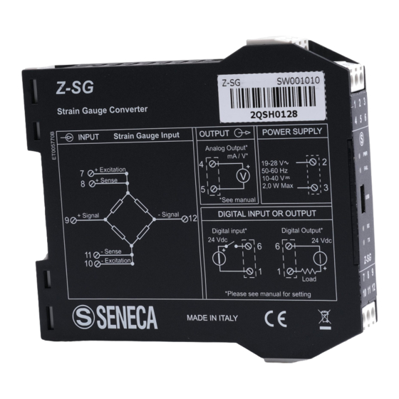
USER MANUAL – Z-SG Non è stata trovata alcuna voce d'indice. Seneca Z-PC Line modules: Z-SG / Z-SG-L The Z-SG / Z-SG-L modules allows to manage the load cell signals and to process the weight value. General characteristics ADC with 24bits resolution... -
Page 3: Power Supply
USER MANUAL – Z-SG 350Ω), up to 8 load cells (if each cell has input impedance: 1000Ω) Cell sensitivity Configurable between: ±1mV/V; ±2mV/V; ±4mV/V; ±8mV/V; ±16mV/V; ±32mV/V; ±64mV/V by Dip-Switches. Cell sensitivity can be acquired by register (in alternative) Internal load cell... - Page 4 USER MANUAL – Z-SG Functioning and connections Z-SG / Z-SG-L setting parameters are: digital input/output, analog output, operating modality, load cell sensitivity. These parameters are settable only by Dip-Switches (except load cell sensitivity, settable by Dip-Switches and by bus communication).
- Page 5 4 and 5. STABLE WEIGHT Z-SG / Z-SG-L module allows to detect when a weight is stable: weight stability information is available through bit40066.4 or through digital output. In particular, a weight measure is stable if the weight variation of net weight (reg.40064, 40065), in a given time interval (“delta time”, reg.40058), is less than weight interval (“delta weight”,...
- Page 6 Z-SG module allows to activate a digital input or (in alternative) a digital output only by Dip- Switch. In the Z-SG model the digital input allows to storage tare value and it can be always used in alternative to calibration button, in the Z-SG-L model the digital input can be used for acquire a general purpose input.
- Page 7 The module acquires load cell sensitivity from register 40044, 40045 (FP): in this case, real numbers for sensitivity are allowed RS485 TERMINATOR (Dip-Switches: SW3) Meaning RS485 terminator disabled RS485 terminator enabled RS485 Register table Generic parameters of Z-SG/Z-SG-L module are shown in the following table. Name Range Interpretation of Default Address register...
- Page 8 USER MANUAL – Z-SG memory; 1=gross weight is less than tare-value saved in memory 0=gross weight is less than load cell end scale; Bit 1 1=gross weight is greater than load cell end scale 0=net weight is less than Threshold (reg.40054, 40055...
- Page 9 USER MANUAL – Z-SG register (40060) values are allowed Register (40060) value Sampling frequency 50Hz rejection 60Hz rejection (Hz) decimal 001B 151.71 0037 74.46 0052 49.95 006D 37.59 009B 50.57 00B7 24.82 00D2 16.65 00ED 12.53 Resolution 40059 0=resolution value is acquired from bit[14:8]; 1=resolution...
- Page 10 USER MANUAL – Z-SG 5=115200; 6=1200; 7=2400 Delay for RS485 (delay of communication response: it Bit [7:0] represents the number of the pauses(*) between the end of Rx message and the start of Tx message): from 0x00=0 to 0xFF=255 (*)1 pause=6 characters Load-cell configuration parameters are shown in the following table.
- Page 11 USER MANUAL – Z-SG 4mA) Max tech net- FP32bit_MSW 40050 weight MSW Max tech net- FP32bit_LSW 40051 weight LSW Max technical net weight. It corresponds to the analog 10000 output end scale (settable by Dip-Switches: 5V, 10V, [mg, 20mA) kg, etc…] ADC value is shown in the following table.
- Page 12 8) Write known weight value in reg. 40048, 40049 (FP) 9) Reset the module (write 0xABAC=43948 in reg.40068) New sensitivity and known weight are saved in Z-SG/Z-SG-L module. 10) Put the tare on the balance 11) Save the tare value in EEPROM memory (write 0xC2FA=49914 in reg.40068)
-
Page 13: Factory Calibration
7) Write sensitivity value in reg. 40044, 40045 (FP) 8) Write load cell end scale in reg. 40046, 40047 (FP) New sensitivity and load cell end scale are saved in Z-SG / Z-SG-L module. 10) Put the tare on the balance... - Page 14 USER MANUAL – Z-SG Setting by calibration button There are two alternative modalities to configure the Z-SG / Z-SG-L module by calibration button (if the user has not a Personal Computer and has a known weight that corresponds to the analog output end scale).
- Page 15 USER MANUAL – Z-SG 11) Keep pushed the calibration button (or in alternative use digital input signal for Z-SG model) until LED ERR switches from flashing to “OFF” The module has acquired the tare value. 12) Keep pushed the calibration button (or in alternative use digital input signal) until LED ERR is “ON”...
- Page 16 The Z-SG / Z-SG-L module has acquired tare value: this value is saved in EEPROM (keep saved when the module is power off). 9) Power off the module 10) Switch the Dip-Switches SW2-4 to “OFF” and SW2-5 to “OFF”. In this way, Z-SG / Z-SG-L module is calibrated. 11) Power on the module When calibration procedure is ended, it is possible to calibrate the module by the digital input (only Z-SG model) or by calibration button (after switching SW2-1 to “OFF”: digital...
- Page 17 USER MANUAL – Z-SG If technical net weight is equal to real end scale, analog output will result 50kg 10kg X 100=80% 50kg and 80% corresponds to an analog output equal to 8V. Remote Memorizing of the Tare The memorizing of the tare may be perfomed in the following ways:...
- Page 18 USER MANUAL – Z-SG Blinking light The module sent a data packet Easy-SETUP To configure the Seneca Z-PC Line modules, it is possible to use Easy-SETUP software, Free-downloadable from the www.seneca.it; the configuration can be performed by RS232 or RS485 bus communication.
Need help?
Do you have a question about the Z-SG and is the answer not in the manual?
Questions and answers