Table of Contents
Advertisement
Quick Links
Z-PC Line
Z-PC Line
EN
EN
Installation
Installation
Manual
Manual
Contents:
- General description
- Technical specifications
- Connection rules for Modbus and
CAN
- Installation rules
- Electrical connections
- Status indications LED
- Default settings
- Frontal panel
- Accessories
- Disposal.
SENECA s.r.l.
Via Austria, 26 – 35127 – PADOVA – ITALY
Tel. +39.049.8705355 - 8705359 - Fax +39.049.8706287
Configuration software and manuals on our site www.seneca.it
Technical support: support@seneca.it
Product informations: sales@seneca.it
This document is the property of SENECA Srl. Unauthorized duplication and reproduction are forbidden. The content of the present
documentation refers to products and technologies described herein. Such data can be modified and supplemented for technical
and/or commercial reasons.
4 Channels RTD input module
with RS485 interface
MI00441-3-EN
Z-4RTD2
ENGLISH 1/8
Advertisement
Table of Contents

Related Manuals for Seneca Z-4RTD2


Summary of Contents for Seneca Z-4RTD2
- Page 1 Technical support: support@seneca.it Product informations: sales@seneca.it This document is the property of SENECA Srl. Unauthorized duplication and reproduction are forbidden. The content of the present documentation refers to products and technologies described herein. Such data can be modified and supplemented for technical and/or commercial reasons.
-
Page 2: General Description
1.5 kV insulation between the inputs, the power supply and serial communication line. Ÿ Easy and fast wiring of power supply and serial communications by means of Seneca Ÿ bus for DIN rail IEC EN 60715. Communication parameters can be configured by DIP-switch or through USB port from Ÿ... - Page 3 0.04 % On resistor, with Full Scale of: 14 bit or 13 bit Resolution: Calibration Precision: (PT100, NI100) or on input range 1850 (PT500, PT1000) 0.025 % On resistor, Class\Base Precision: 0.05 with Full Scale of: Linearity: (PT100, NI100) or Thermal Drift: <...
-
Page 4: Installation Rules
I n p I s o l a t back connector to the female connector on the Seneca DIN IEC EN 60715 rail support. 1 2 3 4 5 6 7 8 3) To secure the module on the rail support... -
Page 5: Electrical Connections
Electrical connections POWER SUPPLY AND RS485 COMMUNICATION PORT Power supply and MODBUS interface are available from the bus for Seneca DIN rail through the accessory Z-PC-DINAL1-35 from the rear IDC10 connector. Detailed RS485 serial interface information can be found in the USER MANUAL downloadable from the website : www.seneca.it/products/z-4rtd2... -
Page 6: Dip Switch Settings
DIP-Switch settings 1Ç In the following tables: Ç The symbol Ç corresponds to DIP-Switch = 1 (ON). 0È No indication correspond to DIP-switch = 0 (OFF) DIP-Switch SW1 You must set the DIP-switches with the module powered down and without generation of electrostatic discharges, otherwise the module may be damaged. -
Page 7: Factory Configuration
A second way to program the module is through the micro USB connector on the frontal panel by using a PC or an Android device after installation of the necessary software. For more information visit www.seneca.it/prodotti/z-4rtd2 Factory Configuration Configuration of the default parameters in the module: The instrument is configured at the factory with all the DIP-switch in position 0 È... -
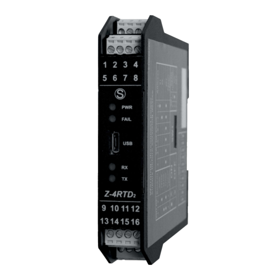
Page 8: Front Led Indications
Front LED indications STATUS Description PWR Green The device is powered correctly. FAIL Yellow Fault: Low supply, faulty channel, faulty sensor, internal communication error ( they can be deactivated via software). RX Red It indicates data receiption on RS485 communication port. TX Red It indicates the data transmission on RS485 communication port.
Need help?
Do you have a question about the Z-4RTD2 and is the answer not in the manual?
Questions and answers