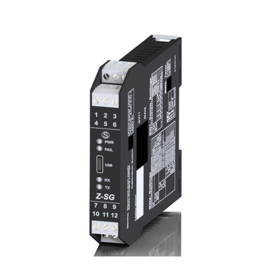
Seneca Z-SG User Manual
Advanced digital strain gauge converter
Hide thumbs
Also See for Z-SG:
- User manual (18 pages) ,
- Installation manual (9 pages) ,
- Installation manual (8 pages)
Table of Contents
Advertisement
Quick Links
USER MANUAL
This document is property of SENECA srl. Duplication and reproduction are forbidden, if not authorized. Contents of the present
documentation refers to products and technologies described in it. All technical data contained in the document may be modified
without prior notice Content of this documentation is subject to periodical revision.
To use the product safely and effectively, read carefully the following instructions before use. The product must be used only for the
use for which it was designed and built. Any other use must be considered with full responsibility of the user. The installation,
implementation and set-up is allowed only for authorized operators; these ones must be people physically and intellectually suitable.
Set up must be performed only after a correct installation and the user must perform every operation described in the installation
manual carefully. Seneca is not considered liable of failure, breakdown, accident caused for ignorance or failure to apply the indicated
requirements. Seneca is not considered liable of any unauthorized changes. Seneca reserves the right to modify the device, for any
commercial or construction requirements, without the obligation to promptly update the reference manuals.
No liability for the contents of this documents can be accepted. Use the concepts, examples and other content at your own risk. There
may be errors and inaccuracies in this document, that may of course be damaging to your system. Proceed with caution, and although
this is highly unlikely, the author(s) do not take any responsibility for that. Technical features subject to change without notice.
Z-SG / Z-SG-L
Advanced Digital
Strain gauge converter
SENECA s.r.l.
Via Austria, 26 – 35127 –PADOVA – ITALY
Tel. +39.049.8705355 – 8705359 Fax. +39.049.8706287
Web site:
www.seneca.it
Technical assistance:
supporto@seneca.it
Commercial reference:
commerciale@seneca.it
MI003790
MI002636
(IT),
support@seneca.it
(IT),
Page 1
(Other)
sales@seneca.it
(Other)
Advertisement
Table of Contents

Related Manuals for Seneca Z-SG


Summary of Contents for Seneca Z-SG
- Page 1 Set up must be performed only after a correct installation and the user must perform every operation described in the installation manual carefully. Seneca is not considered liable of failure, breakdown, accident caused for ignorance or failure to apply the indicated requirements.
- Page 2 USER MANUAL – Z-SG Date Revision Notes 15/04/2016 New revision 28/09/2016 Correct example at chapter 11.2 21/10/2019 Edited chapter: Calibration with a standard weight Fix Analog Input Features...
-
Page 3: Table Of Contents
3. FEATURES ........................5 4. LEDS FOR SIGNALLING ..................... 7 5. LOAD CELL: 4 OR 6 WIRES CONNECTION .............. 8 6. ANALOG OUTPUT (ONLY Z-SG MODEL) ..............9 7. “STABLE WEIGHT” CONDITION ................9 8. DIGITAL INPUT / DIGITAL OUTPUT ................9 9. - Page 4 UNDER ANY CIRCUMSTANCES, SENECA S.R.L. OR ITS SUPPLIERS SHALL NOT BE RESPONSIBLE FOR LOSS OF RECORDING DATA/INCOMES OR FOR CONSEQUENTIAL OR INCIDENTAL DAMAGE DUE TO NEGLECT OR RECKLESS MISHANDLING OF Z-SG / Z-SG-L, EVEN THOUGH SENECA IS WELL AWARE OF THESE POSSIBLE DAMAGES.
-
Page 5: Glossary
4 wires or 6 wires load cell measure mode Compression and Traction or only compression load mode NR 1 analog output configurable in Current or Voltage mode (only Z-SG model) Load cell sensitivity configurable from +-1mV/V to +-64mV/V or virtually every sensitivity ... - Page 6 Dip-Switches. Max resistance that can be connected: 500 LOAD CELLS A load cell or more load cells (if they are parallel-connected) can be connected to the Z-SG module. Minimum impedance that can be connected: 87 . This value can Load impedance be equivalent impedance of more parallel-connected load cells.
-
Page 7: Leds For Signalling
USER MANUAL – Z-SG POWER SUPPLY 10 – 40 Vdc or 19 – 28 Vac ( 50Hz - 60Hz) Supply voltage Power Max: 2W consumption The power supply transformer necessary to supply the module must be comply with EN60742 (Isolated transformers and safety transformers requirements). -
Page 8: Load Cell: 4 Or 6 Wires Connection
Load cell output signal (-) - Sense Reading of load cell power (-) - Excitation Load cell power (-) To connect the Z-SG / Z-SG-L to load cell in 4-wires mode: - short-circuit screw terminal 7 to screw terminal 8;... -
Page 9: Analog Output (Only Z-Sg Model)
The Analog Output 0% and 100% can be fully configurable. 7. “STABLE WEIGHT” CONDITION Z-SG / Z-SG-L module allows to detect when a weight measure is stable: weight stability information is available through 40066 Modbus register (bit Nr 4) or through digital output. -
Page 10: Dip-Switches Table
USER MANUAL – Z-SG ”V” means equivalent voltage generator. Z-SG / Z-SG-L module can be configured in digital input mode or (in alternative) in digital output mode only by Dip-Switch. In the Z-SG model the digital input can be used for:... - Page 11 USER MANUAL – Z-SG BAUD-RATE (Dip-Switches: SW1) Meaning Baud-rate=9600 Baud Baud-rate=19200 Baud Baud-rate=38400 Baud Baud-rate=57600 Baud ADDRESS (Dip-Switches: SW1) Meaning Address and Baud-Rate are acquired from memory(EEPROM) Address=1 Address=2 Address=3 Address=4 …………………… Address=63 DIGITAL INPUT/OUTPUT (Dip-Switches: SW2) Meaning Digital input. Calibration button (used during calibration procedure) is enabled...
-
Page 12: Measure Calibration With Modbus Registers
USER MANUAL – Z-SG Factory calibration Calibration with Standard weight Factory calibration using calibration button (or digital input in Z-SG model) Calibration with known weight using calibration button (or digital input in Z-SG model) LOAD CELL SENSITIVITY (Dip-Switches: SW2) Meaning ±1 mV/V ±2 mV/V... -
Page 13: Calibration With A Standard Weight
USER MANUAL – Z-SG Use the software “Easy Setup” (download from www.seneca.it) for Configure and Calibrate the Z-SG/Z-SG-L. 10.2. CALIBRATION WITH A STANDARD WEIGHT WARNING Gross weight (tare + Standard weight) must not to exceed load cell end scale, to avoid serious damage to the cell. -
Page 14: Measure Calibration Without Modbus Registers
7) Write sensitivity value in reg. 40044, 40045 (FP) 8) Write load cell end scale in reg. 40046, 40047 (FP) New sensitivity and load cell end scale are saved in Z-SG / Z-SG-L module. 10) Put the tare on the balance 11) Save the tare value in EEPROM memory (write 0xC2FA=49914 in reg.40068) -
Page 15: Calibration Without A Standard Weight Using The Calibration Button
USER MANUAL – Z-SG 6) Power on the module 7) Keep pushed the calibration button (or in alternative, only for Z-SG model, use digital input) until LED ERR is “ON” 8) Release the calibration button 9) Control that the LED ERR is flashing... - Page 16 The Z-SG / Z-SG-L module has acquired tare value: this value is saved in EEPROM (keep saved when the module is power off). 9) Power off the module 10) Switch the Dip-Switches SW2-4 to “OFF” and SW2-5 to “OFF”. In this way, Z-SG / Z-SG-L module is calibrated. 11) Power on the module When calibration procedure is ended, it is possible to calibrate the module by the digital input (only Z-SG model) or by calibration button (after switching SW2-1 to “OFF”: digital...
-
Page 17: Easy-Setup
So the 32bits value is obtained by the following relation: NetWeight=������40064+(������40065×2^16)=������40064+(������40065 ×65536) For the floating point values the Z-SG-L model can Swap the Most significant word with the Less significant word. For more information about this protocol please refer to Modbus specification website:... -
Page 18: Modbus Function Code Supported
“Signed 16 bit” = 16 bit register with sign “Float 32 bits” = Floating point single precision 32 bits (IEEE 754) register “0x” = Hexadecimal Value Generic parameters of Z-SG/Z-SG-L module are shown in the following table. REGISTER REGISTER MODBUS... - Page 19 USER MANUAL – Z-SG Firmware Revision unsigned Code Firmware Code 16 bit R Flash 40002 Bit [0] ADC Polarity: 0 = ADC is configured for traction/compression ADC from -31000 to +31000 1 = ADC is configured only for compression ADC from 0 to 62000...
- Page 20 USER MANUAL – Z-SG Weight 32 bit " 0% Analog Floating Net Weight that will generate 0% of the Point "0.00 40052- Weight analog out 32 bit R/W Flash 0" 40053 51-52 Floating Weight Threshold for Digital Output Threshold Point "5000...
- Page 21 USER MANUAL – Z-SG 0x001B 151.71 0x0037 74.46 0x0052 49.95 0x006D 37.59 0x009B 50.57 0x00B7 24.82 0x00D2 16.65 0x00ED 12.53 Number of samples in the moving average for weight Measure. Registers 40064 - 40065 contain the Moving result of moving average.
- Page 22 USER MANUAL – Z-SG this output mode is selected) Z-SG MODEL: not used Bit [4] Weight stability. 0=weight is not stable 1=weight is stable Bit[3] 1=save the tare value in RAM memory Bit [2] 0=gross weight is greater than tare-value saved in memory;...
- Page 23 USER MANUAL – Z-SG Bit [11] Switch5 of “SW1” state. 0= OFF 1 = ON Bit [10] Switch6 of “SW1” state. 0= OFF 1 = ON Bit [9] Switch7 of “SW1” state. 0= OFF 1 = ON Bit Switch8 of “SW1” state. 0= OFF 1 = ON Bit Switch1 of “SW2”...
- Page 24 USER MANUAL – Z-SG High values (MAX = 100) Better Worst Low values (MIN = 1) Worst Better...
Need help?
Do you have a question about the Z-SG and is the answer not in the manual?
Questions and answers