Table of Contents
Advertisement
Quick Links
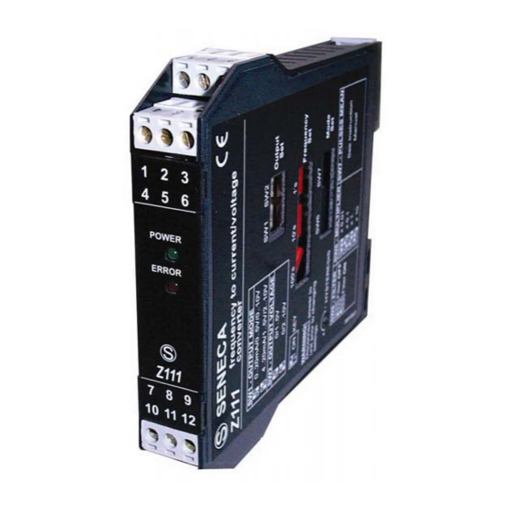
FREQUENCY => CURRENT / VOLTAGE CONVERTER
EN
GENERAL FEATURES
Pulse input for all the most commonly-used sensors: mechanical contact, reed, npn
with 2 and 4 wires, pnp with 3 wires and 24V DC power supply, Namur,
photoelectric, variable reluctance, 24V and TTL pulses
Maximum frequency from 1 mHz to 9.99 KHz, selectable fullscale from 10 mHz to
9.99 KHz;
Full-scale can be easily set using rotating switches;
Selection of the output mode (0/4.20 mA, 0/1..5V , 0/2..10V) using dip-switches;
Possibility to set the number of pulses for the calculation of the pulse average;
Indication of power supply presence and out-of-scale errors provided on front panel;
3-point insulation: 1500V AC.
TECHNICAL SPECIFICATIONS
Input:
Output:
Work conditions:
Standards:
19..40 Vdc, 19..28 Vac 50..60 Hz, max 2,5 W
Pulses: mechanical contact, reed , npn with 2 and 3 wires ,
pnp with 3 wires and 24V DC power supply, Namur,
photoelectric, "HALL" sensor, and variable reluctance.
Maximum frequency 9.99 KHz
Active current 0..20 mA / 4..20 mA, max. load resistance: 600
ohm
Voltage 0..5 V / 0..10 V / 1..5 V / 2..10 V , min. load resistance:
2500 ohm
Error : < 0.3% of F.S.
Temperature: 0 - 50°C , Min. humidity: 30% , Max. humidity:
90% at 40°C (non condensing)
The instrument conforms to the following standards:
EN50081-2 (electromagnetic emission, industrial environments)
EN50082-2 (electromagnetic immunity, industrial environments)
EN61010-1 (safety)
Notes:
- Use with copper conductor.
- Use in Pollution Degree 2 Environment .
- Power Supply must be Class 2.
- When supplied by an Isolated Limited Voltage/Limited
Current power supply a fuse rated max 2.5 A shall be
installed in the field.
MI00035 -E
Z111
9
ENGLISH - 1/8
Advertisement
Table of Contents

Related Manuals for Seneca Z111


Summary of Contents for Seneca Z111
- Page 1 FREQUENCY => CURRENT / VOLTAGE CONVERTER Z111 GENERAL FEATURES Pulse input for all the most commonly-used sensors: mechanical contact, reed, npn with 2 and 4 wires, pnp with 3 wires and 24V DC power supply, Namur, photoelectric, variable reluctance, 24V and TTL pulses Maximum frequency from 1 mHz to 9.99 KHz, selectable fullscale from 10 mHz to...
- Page 2 INSTALLATION RULES The Z111 modules have been designed for mounting on DIN 46277 guides in vertical position. For long-lasting and optimum working life, the module(s) must be ensured adequate ventilation. Make sure to position the cable raceways and any other objects in such way as to avoid clogging the ventilation slots.
- Page 3 ELECTRICAL CONNECTIONS We recommend using shielded cables for the connection of the signals; the shield must be connected to a designated ground connection for the instrurmentation. We also discourage passing the wires near the power supply cables for inverters, motors, or induction ovens, etc.
- Page 4 NOTE : In order to permit the use of the variable reluctance type input, the internal jumpers must be selected. Before setting the internal jumpers, the container's lateral closing panel must be removed by pulling it slightly outward. The instrument is supplied with internal jumpers set for standard inputs.
- Page 5 HISTERESYS CALIBRATION This operation is only performed when the “variable reluctance” input is used. For the hysteresis calibration, after first correctly setting the internal jumpers and the full- scale frequency, a tester must be connected to the device's output (it makes no difference whether the voltage or current output is used) and an input signal must be provided;...
- Page 6 INPUT FREQUENCY SETTING The input signal full-scale frequency can be easily set. The three rotating selectors permit the setting of a value which when multiplied by the multiplication factor will provide the input signal full-scale frequency. Example 1 : if the input frequency full-scale value = 563 Hz, the hundredths (100's) selector must be set to 5, the tenths (10's) selector must be set to 6, and the units (1's) selector must be set to 3.
- Page 7 PULSE AVERAGE SETTING Whenever the input signals present cyclically unstable frequency, a number of pulses on which the frequency measurement will be calculated can be set. Example : the input signal is provided by a proximity sensor that indicates the passage of a number of bolts mounted on a wheel;...
- Page 8 This document is property of SENECA srl. Duplication and reprodution are forbidden, if not authorized. Contents of the present documentation refers to products and technologies described in it. All technical data contained in the document may be modified without prior notice Content of this documentation is subject to periodical revision.
Need help?
Do you have a question about the Z111 and is the answer not in the manual?
Questions and answers