Table of Contents
Advertisement
Quick Links
INSTALLATION MANUAL
Z204-1
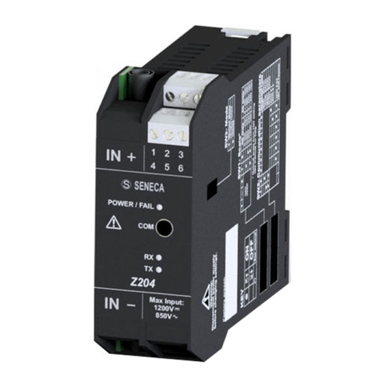
True RMS AC / DC converter with Modbus protocol on RS485
EN
SENECA s.r.l.
Via Austria, 26 – 35127 – PADOVA – ITALY
Tel. +39.049.8705355 - 8705359 - Fax +39.049.8706287
For manuals in French, German, English and configuration software, visit the
www.seneca.it/products/204-1
website
This document is the property of SENECA srl. Copies and reproduction are prohibited unless authorised. The
content of this document corresponds to the described products and technologies. Stated data may be modified
or supplemented for technical and/or sales purposes.
ENGLISH - 1/8
MI003615-E
THE ORIGINAL VERSION IS IN ITALIAN LANGUAGE
Advertisement
Table of Contents

Related Manuals for Seneca Z204-1


Summary of Contents for Seneca Z204-1
- Page 1 This document is the property of SENECA srl. Copies and reproduction are prohibited unless authorised. The content of this document corresponds to the described products and technologies. Stated data may be modified or supplemented for technical and/or sales purposes.
- Page 2 TECHNICAL SPECIFICATIONS EN61000-6-4 electromagnetic emissions, industrial environment EN61000-6-2. Electromagnetic immunity, industrial environment. EN61010-1 (safety) STANDARDS Install a fuse with a maximum capacity of 2.5 A near the module For voltages over 1000 V , install a 4kV overvoltage protection device RS232 Configuration 1500 V...
- Page 3 WARNING: The full content of this manual must be read before operation. The module must only be used by qualified electricians. Specific documentation is available from www.seneca.it/prodotti/ Z204-1. The module must be repaired and damaged parts replaced by the Manufacturer. The product is sensitive to electrostatic discharges.
- Page 4 L/ B IDC10 H / A Z-PC-DINAL SUPPLY AND MODBUS INTERFACE Supply and MODBUS interface are available via the Seneca BUS. Access to the Seneca BUS is available via the IDC10 connector, or via the Z-PC-DINAL-35 accessory. ENGLISH - 4/8...
- Page 5 ELECTRICAL CONNECTIONS WARNING BEFORE CARRYING OUT ANY INSTRUMENT CONNECTIONS, MAKE SURE THAT YOU DISCONNECT ALL THE CIRCUITS SUBJECT TO A DANGEROUS VOLTAGE. TO CONNECT THE HIGH VOLTAGE INPUT USE ONLY THE PLUGS SUPPLIED WITH THE INSTRUMENT Insertion of high voltage plugs The figure at the side shows the insertion points of the two 4mm banana plugs supplied with the instrument.
- Page 6 User Manual. For the variation of the parameters, the communication software is available in the download area of the www.seneca.it website: Z-NET and EASY-SETUP. With all DIP-switches in the OFF position (the communication parameters are taken from the memory).
- Page 7 To obtain the best resolution, select through the SW1 Dip-Switch group the input scale (among the four in the previous table) whose full scale is closer to and higher than the value to be measured. After selecting the measurement range, it is necessary to configure via software the desired start and full scale within the selected range and then the current or voltage values that you want to retransmit as the measurement start and full scale.
- Page 8 SUPPLY AND MODBUS INTERFACE Electrical power connections are available from both terminals and using the Seneca DIN guide bus. Connections relative to the MODBUS RS485 interface are instead available using the DIN rail bus or, after configuring the SW3 DIP-switch to ON, through terminals 4, 5 and 6.
Need help?
Do you have a question about the Z204-1 and is the answer not in the manual?
Questions and answers