Seneca Z-SG Installation Manual
Hide thumbs
Also See for Z-SG:
- User manual (18 pages) ,
- Installation manual (9 pages) ,
- User manual (24 pages)
Table of Contents
Advertisement
Quick Links
PRELIMINARY WARNINGS
The word WARNING preceded by the symbol
The word ATTENTION preceded by the symbol
instrument or connected equipment.
The warranty shall become null and void in the event of improper use or tampering with the module or devices
supplied by the manufacturer as necessary for its correct operation, and if the instructions contained in this manual
are not followed.
WARNING: The full content of this manual must be read before any operation. The module must only be used by
qualified electricians. Specific documentation is available using the QR-CODE shown on page 1.
The module must be repaired and damaged parts replaced by the Manufacturer. The product is sensitive to electro-
static discharges. Take appropriate measures during any operation.
Electrical and electronic waste disposal (applicable in the European Union and other countries with recycling). The
symbol on the product or its packaging shows the product must be surrendered to a collection centre authorized to
recycle electrical and electronic waste.
SENECA s.r.l.; Via Austria, 26 – 35127 – PADOVA – ITALY; Tel. +39.049.8705359 - Fax +39.049.8706287
CONTACT INFORMATION
Technical support
This document is the property of SENECA srl. Copies and reproduction are prohibited unless authorised.
The content of this document corresponds to the described products and technologies.
Stated data may be modified or supplemented for technical and/or sales purposes.
MI00532-3-EN
INSTALLATION MANUAL
Z-SG
DOCUMENTATION
supporto@seneca.it
INSTALLATION MANUAL
indicates conditions or actions that put the user's safety at risk.
indicates conditions or actions that could damage the
Z-SG
Product information
commerciale@seneca.it
1/7
Advertisement
Table of Contents

Related Manuals for Seneca Z-SG


Summary of Contents for Seneca Z-SG
- Page 1 Z-SG DOCUMENTATION SENECA s.r.l.; Via Austria, 26 – 35127 – PADOVA – ITALY; Tel. +39.049.8705359 - Fax +39.049.8706287 CONTACT INFORMATION Technical support supporto@seneca.it Product information commerciale@seneca.it...
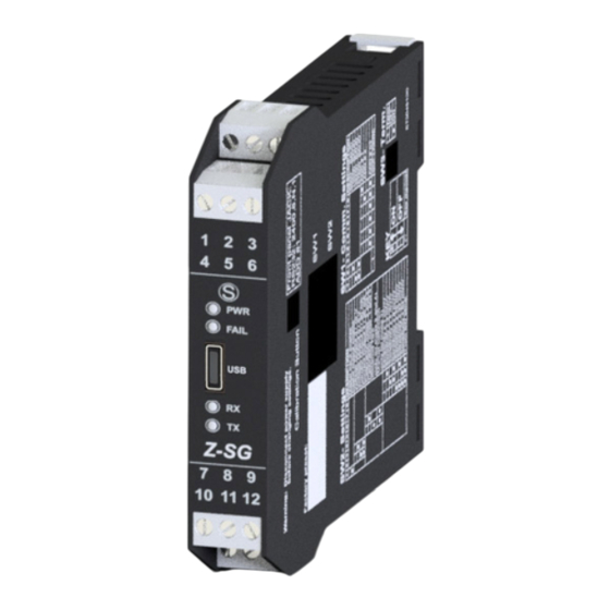
- Page 2 MODULE LAYOUT 17.5 mm 111 mm Dimensions LxHxD 17.5 x 102.5 x 111 mm; Weight: 110 g; Enclosure: PA6, black SIGNALS VIA LED ON FRONT PANEL STATUS LED meaning PWR Green The device is powered correctly FAIL yellow Faulty RX Red Flashing Receipt of packet completed RX Red...
- Page 3 TECHNICAL SPECIFICATIONS CERTIFICATIONS ModBUS WARNING RS485 the maximum working voltage between Communication any terminal and ground must be less than INSULATION Input Output 50 Vac / 75Vdc Power Supply 1500 dc / 10..40V 19..28Va -10 ÷ + 65°C emperature: 30% ÷ 90% non condensing. Humidity: ENVIRONMENTAL Altitude:...
- Page 4 SETTING THE SW1 DIP-SWITCHES: The position of the DIP-switches defines the Modbus communication parameters of the module: Address and Baud Rate The following table shows the Baud Rate and Address values according to the DIP-switch setting: DIP-Switch status SW1 POSITION SW1 POSITION BAUD ADDRESS...
- Page 5 USB port cable. EASY SETUP (for Windows systems) is the software to be used for the configuration and calibration of the load cell. For more information, visit www.seneca.it/prodotti/z-sg. (*) Check that the device in question is included in the list of products supported by the Easy Setup APP in the store.
- Page 6 • separate shielded cables from other cables used for power installations (inverters, motors, induction ovens, etc...). Power supply and Modbus interface are available using the Seneca DIN rail bus, via the IDC10 rear connector, or the Z-PC-DINAL-17.5 accessory. Back connector (IDC 10)
- Page 7 Digital input/output Depending on the settings, it is possible to decide whether to have a digital output or input. The connections in the two cases are shown below: Digital input Digital output Ingress o Digitale Usc ita Digitale Load 24 Vdc 24 Vdc Connection to the load cell via 4 or 6 wires: The figure shows the connections to be made for a connection to a load cell.
Need help?
Do you have a question about the Z-SG and is the answer not in the manual?
Questions and answers