Table of Contents
Advertisement
Quick Links
Advertisement
Table of Contents

Subscribe to Our Youtube Channel
Related Manuals for Parker IQAN-MD3


Summary of Contents for Parker IQAN-MD3
- Page 1 Instruction book ® IQAN-MD3 Publ no HY17-8395-IB/UK Edition February, 2009...
-
Page 2: Table Of Contents
IQAN-MD3 menu system ........ - Page 3 Dimensioning of the IQAN-MD3 module ........
-
Page 4: Introduction
Ignoring this could result in damage to the product. Contact the manufacturer if there is anything you are not sure about or if you have any questions regarding the product and its handling or maintenance. The term "manufacturer" refers to Parker Hannifin Corporation. Instruction book, IQAN- MD3... -
Page 5: Precautions
General safety regulations Precautions Precautions General safety regulations Work on the hydraulics control electronics may only be carried out by trained personnel who are well-acquainted with the control system, the machine and its safety regulations. ARNING Mounting, modification, repair and maintenance must be carried out in accordance with the manufacturer's regulations. -
Page 6: Safety During Start-Up
General safety regulations Precautions Safety during start-up ARNING The machine's engine must not be started before the control system is mounted and its electrical functions have been verified. Ensure that no one is in front, behind or nearby the machine when first starting up the machine. -
Page 7: Product Description
The IQAN-MD3 module. System overview The master module, IQAN-MD3, is the central unit in the system. IQAN-MD3 has three CAN buses. Two buses support ICP and are able to control expansion units such as XA2, XS2, XT2, Lx and XR. SAE J1939 and Generic CAN are also supported on the CAN buses and gives the possibility to interface to 3rd party units. -
Page 8: I/O Overview
(7) Voltage inputs VIN-A, VIN-B, VIN-C, VIN-D..VIN-G (7) Digital inputs DIN-A, DIN-B, DIN-C, DIN-D..DIN-G There is a digital output, DOUT-A, on IQAN-MD3 that may be activated when there is an error message for the system, such as a short-circuit and input or output interruption. -
Page 9: Diagnostics
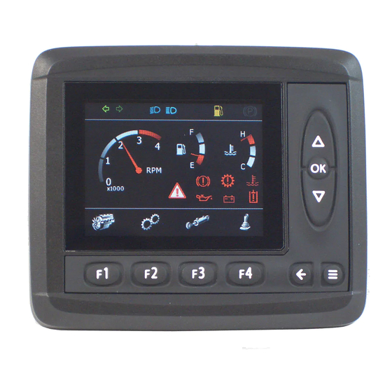
IQAN-MD3 front panel HMI. Features IQAN-MD3 has a 3.5" transflective TFT color display, 320x240 pixels for reading system information. The front of IQAN-MD3 consists of a control panel with a display and nine buttons. • F1 thru F4 function buttons. -
Page 10: Display
Back of unit If the rear surface of the IQAN-MD3 unit is exposed and will be subjected to high pressure steam cleaning, care should be taken around the connector assemblies. The Deutsch DTM connectors are IP67 rated which is suitable for any type of outdoor conditions. -
Page 11: Iqan-Md3 Menu System
Menu navigation flowchart. Overview The menu system is an easy to use set of pages in the IQAN-MD3 that allow you to see module information and logs, set preferences, measure system I/O or adjust parameters. All of this is done using the control and function buttons on the face of the IQAN- MD3. -
Page 12: System Information
Information page. Preferences To set preferences for the IQAN-MD3 press the button on the main menu page under the ’Preferences’ icon, F3. This will bring up the preferences page. Other button options now appear for the function buttons that allow you to set preferences for the display, date/time or language. -
Page 13: Measuring
Measure page. Adjusting If you would like to adjust any channels using the IQAN-MD3 press the button on the main menu page under the ’Adjust’ icon, F1. This will bring up the adjust page that displays the adjustable groups that have been set up in IQANdesign. To select an adjustable group you press the up or down buttons until it is highlighted and then press ’OK’. - Page 14 IQAN-MD3 menu system Product description Once you have selected a group, a list of the adjustable channels is displayed. You may select a particular channel in the same way you selected the group, by using the up and down buttons and pressing OK. To choose the plus or minus direction for adjusting, use the appropriate function button F3 or F4.
-
Page 15: Internal Diagnostics
Accessing the diagnostics page. Safe mode If necessary, the IQAN-MD3 may be started in safe mode. When started in safe mode, no application is loaded and nothing is running. The screen shows a default background and a dialog box notifies the user that the unit is in safe mode. This can be useful for... -
Page 16: Safety
Safety Safety General In order to fulfill high safety demands, the IQAN-MD3 uses a real-time operating system for fault tolerant embedded systems. The IQAN-MD3 has an internal watchdog function. If the watchdog detects any software errors, necessary precautions will be activated. -
Page 17: Reliability
General Reliability Reliability General In order to provide the robust performance expected by our customers, the IQAN-MD3 has protections for its internal circuitry. Polarity reversal The IQAN-MD3 is protected against power supply polarity reversal, provided an external fuse, max 3 A (fast) is being used. Polarity reversal can damage the unit if the fuse is not used. -
Page 18: Mounting
Mounting Mounting Mounting the unit The IQAN-MD3 unit should be mounted according to the following instructions. Dashboard or panel assembly • When installing in a dash or panel the recommended panel thickness is 1.0 - 3.5 mm. Use PT40 screws to mount the unit. -
Page 19: Mounting Considerations
Mounting Mounting considerations OTICE IQAN-MD3 shall be positioned in the machine per the following instructions: • The unit is designed for outdoor use. Position the unit in desired location and make sure that it is not exposed to mechanical damage. -
Page 20: Installation
Connectors C1 and C2 Installation Installation Connectors C1 and C2 Connector kit Parker 20073081 C1 (DTM12 key A) Housing, C1 Deutsch no. DTM06-12-SA Pin type Deutsch no. 1062-20-0222 12 11 10 9 Wedge type Deutsch no. WM12S Sealing plug Deutsch no. 0413-204-2005... -
Page 21: Connector Pin Assignments
Connector pin assignments Installation Connector pin assignments Symbol Input Function Output +BAT C1:12 Power supply -BAT C1:1 Power supply +RTC C1:7 Power supply for RTC. +VREF C2:8 Voltage reference for external sensors. Sourcing +5V. -VREF C2:5 Voltage reference for external sensors. Return (0V). CAN-A-L C1:2 CAN low voltage bus line. -
Page 22: Supply Voltage
Supply Voltage Installation Supply Voltage AUTION Before any installation of the IQAN system can take place, make sure the ignition lock is turned off and the battery is disconnected. Emergency stop Make sure an Emergency Stop disconnecting the power supply, is easily accessible at any time. -
Page 23: Diagnostic Interfaces
A high-speed CAN interface is needed to use this feature. Contact Parker for information about supported CAN interfaces. A termination resistor is usually required at the CAN interface on the PC. Parker part number 5030182 or an equivalent 120 ohm resistor may be used. A flying lead cable may be connected to the IQAN-MD3 to provide a connector interface. -
Page 24: Usb And "Ground Loops" (Differences In Ground Potential)
Connecting for USB. OTICE Do not connect the shield from any USB cable to the IQAN-MD3 side. It is recommended that the two data wires, D+ and D-, shall be a twisted pair, 15 twists/ meter. Use -VREF for the ground connection as shown. -
Page 25: Rs232 Connection
The IQAN-MD3 has an RS232 interface to communicate with landline, wireless or satellite modems for remote diagnostic capabilities. Contact Parker for information about supported modems. A flying lead cable may be connected to the IQAN-MD3 to provide a DB9F connector interface. The cables of this type are available from electronic supplier catalogs. -
Page 26: Connecting Sensors And Switches
Connecting sensors and switches Installation Connecting sensors and switches Connecting sensors to the voltage inputs The sensor signal range must be 0-5 Vdc. To detect signal errors such as short circuits or interruptions the active signal range is recommended to be within 0.5-4.5 Vdc. Error detection range Active signal range Error detection range... - Page 27 Connecting sensors and switches Installation Connecting a 2 wire temperature sensor to voltage in When you connect a temperature sensor you may need to use a pull up resistor on the input signal. Please check the technical data for your specific temperature sensor.
- Page 28 Connecting sensors and switches Installation Connecting switches to the inputs Switches could be connected to the inputs, to create a digital on/off signal. The switches may be connected to +VREF and DIN respectively for 5Vdc signal. The current consumption for the input is negligible. EXAMPLE Connect the positive and negative terminals of the switch to +VREF, position C2:8, and DIN-A, position C2:1, respectively.
-
Page 29: Start-Up
Start-up procedures Start-up Start-up Start-up procedures This chapter contains instructions for action to be taken in connection with the initial start. ARNING Risk of injury! If the control system is not fitted properly, the machine could move uncontrollably. The machine’s engine shall not be started before the control system is completely fitted and its signals are verified. -
Page 30: Start The System
Start-up procedures Start-up Start the system Start the system as follows: • Start the engine for the hydraulic system’s pump, assuming that all mentioned preparations have been carried out and have correct values. • Calibrate and adjust input and output signals according to the instructions related to the master menu system and check each and every output function carefully. -
Page 31: Iqan-Md3 Technical Overview
IQAN-MD3 Technical Overview Appendix A Appendix A IQAN-MD3 Technical Overview Absolute Maximum Ratings Limit values Parameter Unit Remark min. typ. max. Ambient temperature, T – 30 °C – 30 Storage temperature Voltage supply on +BAT Reverse polarity protected Voltage on any pin with... -
Page 32: Recommended Operating Conditions
IQAN-MD3 Technical Overview Appendix A Recommended Operating Conditions Limit values Parameter Unit Remark min. typ. max. Ambient temperature, T – 30 °C When the unit detects an internal temperature that exceeds -25°C to +75°C the LCD will be turned off to reduce the risk for permanent damage of the LCD. -
Page 33: I/O
IQAN-MD3 Technical Overview Appendix A = +25 °C (unless otherwise specified) Limit values Parameter Unit Remark min. typ. max. VIN (Voltage input) Signal range low 0.05 Signal range high 4.95 5.00 Input resistance kΩ Signal resolution 5000/4095 = 1.2 Relative accuracy... -
Page 34: Error Messages And Actions
No CAN communication. All output turned off. CAN-L to CAN-H No CAN communication. All output turned off. CAN-termination failure, termina- No effect tion on CAN-termination failure, termina- Dependent on CAN size and number of CAN nodes. tion off Instruction book, IQAN-MD3... -
Page 35: Failure Modes For Vref
2 bus cycles. Failure modes for DIN Failure mode Effect DIN Open No effect on module, not detected DIN Short-circuited to +BAT No effect on module, not detected DIN Short-circuited to -BAT No effect on module, not detected Instruction book, IQAN-MD3... -
Page 36: Dimensioning Of The Iqan-Md3 Module
Dimensioning of the IQAN-MD3 module Appendix C Appendix C Dimensioning of the IQAN-MD3 module unit = mm Instruction book, IQAN-MD3... - Page 37 For latest information visit our website www.iqan.com Information in this instructionbook is subject to change without notice Parker Hannifin Parker Hannifin Publ no HY17-8395-IB/UK Mobile Controls Division Mobile Controls Division Edition 02/2009 SE-435 35 Mölnlycke 203 Pine Street Sweden Forest City, NC28043...
Need help?
Do you have a question about the IQAN-MD3 and is the answer not in the manual?
Questions and answers