Table of Contents
Advertisement
Advertisement
Table of Contents

Related Manuals for Parker IQAN-MD4


Summary of Contents for Parker IQAN-MD4
- Page 1 IQAN-MD4 Instruction book Publ no HY33-8408-IB/UK Edition 2016-10-26...
-
Page 2: Table Of Contents
Addressing ..........16 IQAN-MD4 use of an ID-Tag ....... . . 16 Identification of an IQAN-MD4 by address . - Page 3 Appendix A ........... 27 IQAN-MD4 Technical Overview ........27 Appendix B .
-
Page 4: Introduction
Contact the manufacturer if there is anything you are not sure about or if you have any questions regarding the product and its handling or maintenance. The term "manufacturer" refers to Parker Hannifin Corporation. Instruction book, IQAN... -
Page 5: Overview Of Relevant Documentation
Overview of relevant documentation Introduction Overview of relevant documentation The following publications are relevant for users of this product. The main documentation contains information that is not found elsewhere. The additional documentation contains product information in a compact format, for details on the information found in those documents, consult this manual. -
Page 6: Precautions
Read This Precautions Precautions Work on the hydraulics control electronics may only be carried out by trained personnel who are well-acquainted with the control system, the machine and its safety regulations. ARNING Make sure that you have sufficient knowledge before designing, modifiying or servicing the control system. -
Page 7: Start-Up, Maintenance, And Diagnostics
Read This Precautions Start-up, maintenance, and diagnostics For all personnel carrying out installation, commissioning, maintenance or troubleshooting. ARNING Work on the hydraulics control electronics may only be carried out by trained personnel who are well-acquainted with the control system, the machine and its safety regulations. -
Page 8: Product Description
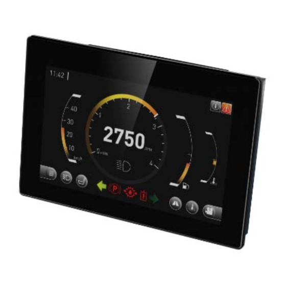
The IQAN-MD4 module. System overview The master module, IQAN-MD4, is the central unit in the system, or in the case of a multi-master system, one of the central units. IQAN-MD4 has four CAN buses and two ethernet ports. The CAN buses support ICP and are able to control IQAN expansion units. -
Page 9: I/O
(2) Digital inputs DIN-I and DIN-J Digital inputs The IQAN-MD4 module has eight (8) digital inputs DIN-A thru DIN-H. DIN-A thru DIN-D are multi purpose and can be configured as low-side on/off outputs. DIN-G and DIN-H are multi purpose and can be configured as a directional pulse count input. see below. -
Page 10: Communication
IQAN-G11 or to a connected PC (requires compatible USB to CAN adapter). In the IQAN-MD4, the CAN channels are paired in groups of 2. There is CAN-A and CAN-B, where the CAN controllers are in the main processor, compared to CAN-C and CAN-D, that are controlled by the co-processor. - Page 11 The backlight is automatically dimmed at supply voltage <14V. Image persistance The IQAN-MD4 TFT LCD, like all other LCD screens, can show image persistence, also known as image sticking, if the same pattern is left on the display for extended periods of time.
-
Page 12: Safety
Internal diagnostics Safety Safety Internal diagnostics The module performs a number of self-checks that improve safety. Checks include monitoring of voltage supplies, checksums on memory and a watchdog that monitors software execution. The module is using a real time operating system which supervises software execution. -
Page 13: Mounting
• The part number for the MD4-5 bracket kit is 20077779. See ’Appendix C’ for RAM™ and Southco mounting pattern dimensions. The IQAN-MD4-10 does not require a bracket. It has a VESA 75 mounting pattern on the back surface which will also accept RAM™ mounts. -
Page 14: Mounting Considerations
Mounting Mounting considerations OTICE IQAN-MD4 shall be positioned in the machine per the following instructions: • The unit is designed for outdoor use. Position the unit in desired location and make sure that it is not exposed to mechanical damage. -
Page 15: Installation
Failure to follow this instruction will cause the module to not meet the environmental specification. Make "Y" connections or splices using weatherproof methods external to the IQAN- MD4 connectors. +BAT CAN-H -BAT CAN-L +RTC CAN-H CAN-L +VREF CAN-H CAN-L CAN-H ETHERNET CAN-L PORT 0 PORT 1 Instruction book, IQAN-MD4... -
Page 16: Connector C1 Pin Assignments
DIN-D DOUT-D C2:7 DIN-E C2:8 DIN-F C2:9 DIN-G +DPCNT-A C2:10 DIN-H -DPCNT-A C2:11 +VREF* C2:12 +RTC *Use -BAT on C1 as -VREF. Make the connection as close to the C1 connector as possible to minimise voltage fluctuation. Instruction book, IQAN-MD4... -
Page 17: Connector C3 And C4
Recommended PC cable 20077780 Sealed panel adapter cable 20077785 Connector C3 and C4 pin assignments Pin No. Symbol Function C3/4:1 Transmit data + C3/4:2 Receive data + C3/4:3 Transmit data - C3/4:4 Receive data - C3/4:Shield Shield Shield Instruction book, IQAN-MD4... -
Page 18: Supply Voltage
Supply voltage Supply voltage Before any installation of the IQAN system can take place, make sure the ignition lock is turned off and the battery is disconnected. Emergency stop Make sure an Emergency Stop disconnecting the power supply, is easily accessible at any time. -
Page 19: Addressing
Identification of an IQAN-MD4 by address For normal operation of an IQAN-MD4 in a single master system, the ID-Tag is still used. When no ID-Tag is installed, the MD4 will start in safe mode. The connection of an ID-Tag between ADDR-H and ADDR-L will assign an address to the IQAN-MD4 master module. -
Page 20: Diagnostic Interfaces
A high-speed CAN interface is needed to use this feature. Contact Parker for information about supported CAN interfaces. A termination resistor is usually required at the CAN interface on the PC. Parker part number 5030082 or 5030182, or an equivalent 120 ohm resistor may be used. A flying lead cable may be connected to the IQAN master to provide a connector interface. -
Page 21: Ethernet Diagnostics Communication
IQANdesign/IQANrun. On port A, the IP address is automatically assigned using DHCP. It is recommended to use an environmentally sealed panel mounted RJ45 connector for easy access. Parker part number 20077785. Video input The IQAN MD4 master modules are capable of showing video inputs from an external source. -
Page 22: Analog Cameras
It is also possible to connect an analog camera by routing the video feed through a video server with ethernet connection. In this case, it is the video server that needs to have the correct IP address set. Instruction book, IQAN-MD4... -
Page 23: Reference Voltage, Vref
VREF. The standard reference voltage will feed different kinds of sensors and potentiometers. On the IQAN-MD4 there is no -VREF pin, instead the -BAT is used as -VREF. To get the best result, connect as close to the connector as possible to minimise voltage fluctuations. -
Page 24: Voltage Inputs
Voltage inputs Voltage inputs Connecting sensors to the voltage inputs The sensor signal range must be 0-5 Vdc. To detect signal errors such as short circuits or interruptions the active signal range be within 0.5-4.5 Vdc. Error detection range Active signal range Error detection range Active signal range. -
Page 25: Connecting A 2-Wire Temperature Sensor To Voltage In
Voltage inputs Connecting a 2-wire temperature sensor to voltage in When you connect a PTC (positive temperature coefficient) temperature sensor you may need to use a pull up resistor on the input signal. Please check the technical data for your specific temperature sensor. EXAMPLE Connect the negative terminal of the temperature sensor to -VREF, and the signal to VIN-X. -
Page 26: Connecting Switches To The Voltage Inputs Using +Bat
Voltage inputs Connecting switches to the voltage inputs using +BAT It is recommended to connect system voltage +BAT to the input through a switch in order to reserve 5Vdc VREF for sensors and potentiometers. EXAMPLE Connect the positive and negative terminals of the switch to supply or the unit’s +BAT, and DIN-X, respectively. -
Page 27: Directional Pulse Count Input
Directional pulse count input Directional pulse count input Connecting a directional pulse count channel (DPCNT) The DPCNT is a physical analog input. The directional pulse count input channel is used to count pulses. It is bi-directional, which means it can add and subtract pulses. The DPCNT is primarily designed for input from an encoder wheel. -
Page 28: Low-Side Digital Outputs
Low-side digital outputs Low-side digital outputs The low-side digital outputs are designed to drive small loads, e.g. lamps and buzzers. Low-side digital outputs work by grounding a signal through the module. See Appendix A for maximum loads per output. EXAMPLE Connect the lamp to the low-side digital outputs using a DOUT(LS) position, and the +BAT, as supply. -
Page 29: Start-Up
Start-up procedures Start-up Start-up Start-up procedures This chapter contains instructions for action to be taken in connection with the initial start. ARNING Risk of injury! If the control system is not fitted properly, the machine could move uncontrollably. The machine’s engine shall not be started before the control system is completely fitted and its signals are verified. -
Page 30: Iqan-Md4 Technical Overview
IQAN-MD4 Technical Overview Appendix A Appendix A IQAN-MD4 Technical Overview Absolute Maximum Ratings Ambient temperature -30 to 70 °C Storage temperature -40 to 85 °C Voltage supply on +BAT 6.5 to 36 V Reverse polarity protection on +BAT 36 V with external 20A fuse (recommended fuse 3A to 5A) - Page 31 IQAN-MD4 Technical Overview Appendix A System = -30 to +70 °C, unless otherwise specified Weight MD4-7 930g MD4-5 670g MD4-10 1500g Ambient temperature, T -30 to 70 °C Voltage supply on +BAT, V 9 to 32 V off below 9 V...
- Page 32 IQAN-MD4 Technical Overview Appendix A LCD - MD4-10 (10.1 inch) Resolution 800 x 600 dots Number of Colors 262 K Active area 211 x 158 mm Brightness 1000 cd/m (reduced to 50% if V <14 V) Viewing angle 80 degree all directions...
- Page 33 IQAN-MD4 Technical Overview Appendix A Signal input - DPCNT Number of DPCNT 1 (configuration may reduce number) Frequency range 0 to 500 Hz, 50/50 signal Minimum pulse width 1 ms Logic levels <0.5 V high >3 V hysteresis >150 mV Input impedance 6.8 kohm...
-
Page 34: Error Messages And Actions
No CAN communication. All output turned off. CAN-L to CAN-H No CAN communication. All output turned off. CAN-termination failure, termina- No effect tion on CAN-termination failure, termina- Dependent on CAN size and number of CAN nodes. tion off Instruction book, IQAN-MD4... -
Page 35: Failure Modes For Vref
2 bus cycles. Failure modes for DIN Failure mode Effect DIN Open No effect on module, not detected DIN Short-circuited to +BAT No effect on module, not detected DIN Short-circuited to -BAT No effect on module, not detected Instruction book, IQAN-MD4... -
Page 36: Dimensioning Of The Iqan-Md4-7
Dimensioning of the IQAN-MD4-7 Appendix C Appendix C Dimensioning of the IQAN-MD4-7 units=mm Instruction book, IQAN-MD4... -
Page 37: Dimensioning Of The Iqan-Md4-5
Dimensioning of the IQAN-MD4-5 Appendix C Dimensioning of the IQAN-MD4-5 units=mm Instruction book, IQAN-MD4... -
Page 38: Dimensioning Of The Iqan-Md4-10
Dimensioning of the IQAN-MD4-10 Appendix C Dimensioning of the IQAN-MD4-10 units=mm Instruction book, IQAN-MD4... -
Page 39: Dimensioning Of The Iqan-Md4 Bracket
Dimensioning of the IQAN-MD4 bracket Appendix C Dimensioning of the IQAN-MD4 bracket Example is MD4-7 bracket RAM™ mount (38,2) Southco mount (49,5) (90°) Ø Typical screw hole magnified units=mm Instruction book, IQAN-MD4... - Page 40 For latest information visit our website www.iqan.com Information in this instructionbook is subject to change without notice Publ no HY33-8408-IB/UK Edition 2016-10-26 Parker Hannifin Parker Hannifin Electronic Controls Division Electronic Controls Division SE-435 35 Mölnlycke 1651 N. Main Street Sweden...
Need help?
Do you have a question about the IQAN-MD4 and is the answer not in the manual?
Questions and answers