Table of Contents
Advertisement
Advertisement
Table of Contents

Related Manuals for Parker IQAN-MD3


Summary of Contents for Parker IQAN-MD3
- Page 1 IQAN-MD3 Instruction book Publ no HY33-8395-IB/UK Edition 2013-04-24...
-
Page 2: Table Of Contents
Addressing ..........20 IQAN-MD3 use of an ID-Tag ....... . . 20 Diagnostic interfaces . - Page 3 Appendix A ........... 28 IQAN-MD3 Technical Overview ........28 Absolute Maximum Ratings .
-
Page 4: Introduction
Contact the manufacturer if there is anything you are not sure about or if you have any questions regarding the product and its handling or maintenance. The term "manufacturer" refers to Parker Hannifin Corporation. Instruction book, IQAN... -
Page 5: Overview Of Relevant Documentation
Overview of relevant documentation Introduction Overview of relevant documentation The following publications are relevant for users of this product. The main documentation contains information that is not found elsewhere. The additional documentation contains product information in a compact format, for details on the information found in those documents, consult this manual. -
Page 6: Precautions
Read This Precautions Precautions Work on the hydraulics control electronics may only be carried out by trained personnel who are well-acquainted with the control system, the machine and its safety regulations. ARNING Make sure that you have sufficient knowledge before designing, modifiying or servicing the control system. -
Page 7: Start-Up, Maintenance, And Diagnostics
Read This Precautions Start-up, maintenance, and diagnostics For all personnel carrying out installation, commissioning, maintenance or troubleshooting. ARNING Work on the hydraulics control electronics may only be carried out by trained personnel who are well-acquainted with the control system, the machine and its safety regulations. -
Page 8: Product Description
The IQAN-MD3 module. System overview The master module, IQAN-MD3, is the central unit in the system, or in the case of a multi-master system, one of the central units. IQAN-MD3 has three CAN buses. The CAN buses support ICP and are able to control IQAN expansion units. SAE J1939 and Generic CAN protocols are also supported on the CAN buses and gives the possibility to interface to 3rd party units. -
Page 9: I/O Overview
(7) Voltage inputs VIN-A, VIN-B, VIN-C, VIN-D..VIN-G (7) Digital inputs DIN-A, DIN-B, DIN-C, DIN-D..DIN-G There is a digital output, DOUT-A, on IQAN-MD3 that may be activated when there is an error message for the system, such as a short-circuit and input or output interruption. -
Page 10: Diagnostics
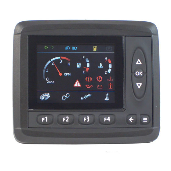
IQAN-MD3 front panel HMI. Features IQAN-MD3 has a 3.5" transflective TFT color display, 320x240 pixels for reading system information. The front of IQAN-MD3 consists of a control panel with a display and nine buttons. • F1 thru F4 function buttons. -
Page 11: Display
Back of unit If the rear surface of the IQAN-MD3 unit is exposed and will be subjected to high pressure steam cleaning, care should be taken around the connector assemblies. The Deutsch DTM connectors are IP67 rated which is suitable for any type of outdoor conditions. -
Page 12: Iqan-Md3 Menu System
Menu navigation flowchart. Overview The menu system is an easy to use set of pages in the IQAN-MD3 that allow you to see module information and logs, set preferences, measure system I/O or adjust parameters. All of this is done using the control and function buttons on the face of the IQAN- MD3. -
Page 13: Preferences
Information page. Preferences To set preferences for the IQAN-MD3 press the button on the main menu page under the ’Preferences’ icon, F3. This will bring up the preferences page. Other button options now appear for the function buttons that allow you to set preferences for the display, date/time or language. -
Page 14: Adjusting
Measure page. Adjusting If you would like to adjust any channels using the IQAN-MD3 press the button on the main menu page under the ’Adjust’ icon, F1. This will bring up the adjust page that displays the adjustable groups that have been set up in IQANdesign. To select an adjustable group you press the up or down buttons until it is highlighted and then press ’OK’. - Page 15 IQAN-MD3 menu system Product description Main press OK to select Adjust Measure Preferences Info Adjust group page. Adjusting a parameter Now you are at the page where the actual adjustment is done. You may toggle through the different parameters by pressing OK repeatedly. When the parameter you wish to adjust is highlighted, you may change it by pressing the up and down buttons.
-
Page 16: Internal Diagnostics
Accessing the diagnostics page. Safe mode If necessary, the IQAN-MD3 may be started in safe mode. When started in safe mode, no application is loaded and nothing is running. The screen shows a default background and a dialog box notifies the user that the unit is in safe mode. This can be useful for... -
Page 17: Safety
Internal diagnostics Safety Safety Internal diagnostics The module performs a number of self-checks that improve safety. Checks include monitoring of voltage supplies, checksums on memory and a watchdog that monitors software execution. The module is using a real time operating system which supervises software execution. -
Page 18: Mounting
Mounting Mounting Mounting the unit The IQAN-MD3 unit should be mounted according to the following instructions. Dashboard or panel assembly • When installing in a dash or panel the recommended panel thickness is 1.0 - 3.5 mm. Use PT40 screws to mount the unit Mv-0.8-1.0 Nm... - Page 19 Mounting the unit Mounting • Leave sufficient room behind the unit to insert connectors. Less than 75 mm clearance will stress the cabling and distort the seals in the connectors. This can cause the environmental specification not to be met. 75 mm 22 mm 48 mm...
-
Page 20: Installation
Connectors C1 and C2 Installation Installation Connectors C1 and C2 Connector kit Parker 20073081 C1 (DTM12 key A) Housing, C1 Deutsch no. DTM06-12-SA Pin type Deutsch no. 1062-20-0222 12 11 10 9 Wedge type Deutsch no. WM12S Sealing plug Deutsch no. 0413-204-2005... -
Page 21: Connector Pin Assignments
Connector pin assignments Installation Connector pin assignments Symbol Input Function Output +BAT C1:12 Power supply -BAT C1:1 Power supply +RTC C1:7 Power supply for RTC. +VREF C2:8 Voltage reference for external sensors. Sourcing +5V. -VREF C2:5 Voltage reference for external sensors. Return (0V). ADDR-L C1:6 Address lowpin for IDtag. -
Page 22: Supply Voltage
Supply voltage Supply voltage Before any installation of the IQAN system can take place, make sure the ignition lock is turned off and the battery is disconnected. Emergency stop Make sure an Emergency Stop disconnecting the power supply, is easily accessible at any time. -
Page 23: Addressing
For normal operation of an IQAN-MD3 in a single master system, the ID-Tag is not used. It is only needed when the IQAN-MD3 is used in a multi-master system, and an address other than ’0’ is needed. The connection of an ID-Tag between +VREF and ADDR-L will assign an address to the IQAN-MD3 master module. -
Page 24: Diagnostic Interfaces
A high-speed CAN interface is needed to use this feature. Contact Parker for information about supported CAN interfaces. A termination resistor is usually required at the CAN interface on the PC. Parker part number 5030082 or 5030182, or an equivalent 120 ohm resistor may be used. A flying lead cable may be connected to the IQAN master to provide a connector interface. -
Page 25: Usb Connection
USB type B connector interface. The connection from the module to PC can be made with a standard USB Type A male to Type B male cable. Connection of Parker cable 5030124 is shown below. IQAN master -VREF... -
Page 26: Reference Voltage, Vref
Reference voltage, VREF Reference voltage, VREF The IQAN module is internally equipped with a voltage regulator to generate the reference voltage VREF. The standard reference voltage will feed different kinds of sensors and potentiometers. IQAN module +VREF -VREF VREF positions. OTICE It is strongly recommended to use the module’s -VREF and +VREF to all sensors and potentiometers that are connected to the module inputs. -
Page 27: Voltage Inputs
Voltage inputs Voltage inputs Connecting sensors to the voltage inputs The sensor signal range must be 0-5 Vdc. To detect signal errors such as short circuits or interruptions the active signal range be within 0.5-4.5 Vdc. Error detection range Active signal range Error detection range Active signal range. -
Page 28: Connecting A 2-Wire Temperature Sensor To Voltage In
Voltage inputs Connecting a 2-wire temperature sensor to voltage in When you connect a PTC (positive temperature coefficient) temperature sensor you may need to use a pull up resistor on the input signal. Please check the technical data for your specific temperature sensor. EXAMPLE Connect the negative terminal of the temperature sensor to -VREF, and the signal to VIN-X. -
Page 29: Connecting Switches To The Voltage Inputs
Voltage inputs Connecting switches to the voltage inputs It is recommended to connect system voltage +BAT to the input through a switch in order to reserve 5Vdc VREF for sensors and potentiometers. EXAMPLE Connect the positive and negative terminals of the switch to supply or the unit’s +BAT, and DIN-X, respectively. -
Page 30: Start-Up
Start-up procedures Start-up Start-up Start-up procedures This chapter contains instructions for action to be taken in connection with the initial start. ARNING Risk of injury! If the control system is not fitted properly, the machine could move uncontrollably. The machine’s engine shall not be started before the control system is completely fitted and its signals are verified. -
Page 31: Appendix A
IQAN-MD3 Technical Overview Appendix A Appendix A IQAN-MD3 Technical Overview Absolute Maximum Ratings Limit values Parameter Unit Remark min. typ. max. Ambient temperature, T – 30 °C – 30 Storage temperature Voltage supply on +BAT Reverse polarity protected Voltage on any pin with... -
Page 32: Recommended Operating Conditions
IQAN-MD3 Technical Overview Appendix A Recommended Operating Conditions Limit values Parameter Unit Remark min. typ. max. Ambient temperature, T – 30 °C When the unit detects an internal temperature that exceeds -25°C to +75°C the LCD will be turned off to reduce the risk for permanent damage of the LCD. -
Page 33: I/O
IQAN-MD3 Technical Overview Appendix A = +25 °C (unless otherwise specified) Limit values Parameter Unit Remark min. typ. max. VIN (Voltage input) Signal range low 0.05 Signal range high 4.95 5.00 Input resistance kΩ Signal resolution 5000/4095 = 1.2 Relative accuracy... -
Page 34: Appendix B
No CAN communication. All output turned off. CAN-L to CAN-H No CAN communication. All output turned off. CAN-termination failure, termina- No effect tion on CAN-termination failure, termina- Dependent on CAN size and number of CAN nodes. tion off Instruction book, IQAN-MD3... -
Page 35: Failure Modes For Vref
2 bus cycles. Failure modes for DIN Failure mode Effect DIN Open No effect on module, not detected DIN Short-circuited to +BAT No effect on module, not detected DIN Short-circuited to -BAT No effect on module, not detected Instruction book, IQAN-MD3... -
Page 36: Appendix C
Dimensioning of the IQAN-MD3 module Appendix C Appendix C Dimensioning of the IQAN-MD3 module unit = mm Instruction book, IQAN-MD3... - Page 37 For latest information visit our website www.iqan.com Information in this instructionbook is subject to change without notice Publ no HY33-8395-IB/UK Edition 2013-04-24 Parker Hannifin Parker Hannifin Electronic Controls Division Electronic Controls Division SE-435 35 Mölnlycke 1651 N. Main Street Sweden...
Need help?
Do you have a question about the IQAN-MD3 and is the answer not in the manual?
Questions and answers