
Subscribe to Our Youtube Channel
Related Manuals for Parker PHD28


Summary of Contents for Parker PHD28
- Page 1 Parker Hannifin Display U s e r G u i d e U G - P H D - 1 0 4 0 0 0 1 - 2 0 1 7 0 7 - 0 1 0...
- Page 2 Offer of Sale The items described in this document are hereby offered for sale by Parker Hannifin Corporation, its subsidiaries or its authorized distributors. This offer and its acceptance are governed by the provisions stated in the "Offer of...
-
Page 3: Table Of Contents
Safety during installation ......................... vii Safety during start-up ........................viii Safety during maintenance and fault diagnosis ................viii 1. About the PHD (Parker Hannifin Display) ............... 1 1.1. Diagram conventions ........................ 4 2. Connectors ........................6 2.1. Pinouts ............................7 3. - Page 4 8.2.2. Jumpers........................38 8.2.3. DB9 Pinout Reference ....................41 9. Mounting the PHD ......................42 9.1. Dimensions ..........................43 9.1.1. PHD28 ........................43 9.1.2. PHD50 ........................44 9.1.3. PHD70 ........................45 10. Understanding PHD software ..................46 11. Environmental protection .................... 47 .............................
-
Page 5: Publication History
Publication History The following table provides an overview of the changes made to this document over the course of its publication history. Release Date Description of Change Rev. 001 First release of this document, 2/10/2016 Rev. 002 Updated per Bus. Dev. feedback, 3/3/2016 Rev. -
Page 6: Safety
Contact the manufacturer if there is anything you are not sure about or if you have any questions regarding the product and its handling or maintenance. The term "manufacturer" refers to Parker Hannifin Corporation. Safety symbols The following symbols are used in this document to indicate potentially... -
Page 7: Welding After Installation
Safety Do not use the product if electronic modules, cabling, or connectors are damaged or if the control system shows error functions. Electronic control systems in an inappropriate installation and in combination with strong electromagnetic interference fields can, in extreme cases, cause an unintentional change of speed of the output function. -
Page 8: Safety During Start-Up
Safety Safety during start-up Danger! Risk of death or injury. Do not start the machine's engine before the control system is mounted and its electrical functions have been verified. Do not start the machine if anyone is near the machine. Safety during maintenance and fault diagnosis Before performing any work on the hydraulics control electronics, ensure that ▪... -
Page 9: About The Phd (Parker Hannifin Display)
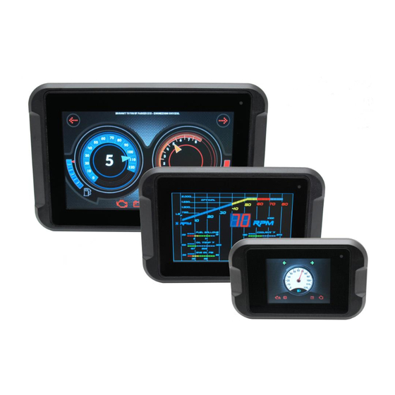
1. About the PHD (Parker Hannifin Display) The PHD family of displays are general purpose displays suitable for a wide range of industry applications. There are 3 sizes: 2.8", 5.0" and 7.0". All models are color LCD displays with capacitive touchscreens for interfacing. - Page 10 About the PHD (Parker Hannifin Display) The different models of the PHD and their features are listed in the following tables: PHD28 Characteristic Description Display 2.8" 320 x 240 TN LCD, PCAP touchscreen Viewing angle Theta X +60° / -60°, Theta Y +60° / -50°...
- Page 11 About the PHD (Parker Hannifin Display) PHD70 Characteristic Description Display 7.0" 800 x 480 IPS LCD, PCAP touchscreen Viewing angle Theta X +80° / -80°, Theta Y +80° / -80° Brightness 500 cd/m² Readable with polarized glasses yes (landscape and portrait orientation)
-
Page 12: Diagram Conventions
About the PHD (Parker Hannifin Display) 1.1. Diagram conventions The following symbols are used in the schematic diagrams in this document: Symbol Meaning General input General output Frequency input Analog input Frequency sensor Pulse sensor Resistive sensor General sensor Application switch... - Page 13 About the PHD (Parker Hannifin Display) Symbol Meaning Pull-up resistor Battery Fuse Resistor Ground Chassis ground User Guide...
-
Page 14: Connectors
Connectors 2. Connectors The connector on the rear panel of the PHD28 is; ▪ MX150 – Vehicle Harness Connector key B The connectors on the rear panel of the PHD50 are; ▪ 2 x MX150 – Vehicle Harness Connectors, key A & B The connectors on the rear panel of the PHD70 are;... -
Page 15: Pinouts
The pins in the Molex MX150 connectors connect to power, inputs, outputs, CAN and USB communication channels. The following tables show the pinouts for each connector: Figure 3: Back of PHD28 showing connector PHD28 J1 Connector Pinout Function GPIO7 (analog or digital input) - Page 16 Connectors Figure 4: Back of PHD50 showing connectors PHD50 J1 Connector Pinout Function GPIO7 (analog or digital input) GPIO1 (analog or digital input) GPIO6 (analog or digital input) OUTPUT2 (low-side output) CAN1_TERM (CAN termination) CAN1_SHLD (CAN shield) CAN1_L (CAN low) CAN1_H (CAN high) GND (Negative battery) +VBATT (Positive battery)
- Page 17 Connectors PHD50 J2 Connector Pinout Function GPIO10 (digital or frequency input) GPIO9 (digital or frequency input) VIDEO1_GND VIDEO1 Ground P12V0 (12V regulated supply) Ground Ground GPIO8 (analog or digital input) P5V0 (5V sensor supply) Reserved for test Reserved for test User Guide...
- Page 18 Connectors Figure 5: Back of PHD70 showing connectors PHD70 J1 Connector Pinout Function GPIO7 (digital input) GPIO1 (digital input) GPIO6 (digital input) OUTPUT2 (low-side output) CAN1_TERM (CAN termination) CAN1_SHLD (CAN shield) CAN1_L (CAN low) CAN1_H (CAN high) GND (Negative battery) +VBATT (Positive battery) GPIO5 (digital input) GPIO4 (digital input)
- Page 19 Connectors PHD70 J2 Connector Pinout Function GPIO10 (digital or frequency input) GPIO9 (digital or frequency input) CAN2_SHLD CAN2_L CAN2_H VIDEO1_GND VIDEO1 VIDEO2 VIDEO2_GND P12V0 (12V regulated supply) Ground Ground GPIO8 (digital input) P5V0 (5V sensor supply) Reserved for test Reserved for test User Guide...
-
Page 20: Inputs
PHD. If an inductive load must be connected to an input, use a protective diode or transorb. 3.1. PHD28 inputs The PHD28 has up to 7 analog inputs: ▪ GPIO1 through... -
Page 21: Phd50 Inputs
Inputs 3.2. PHD50 inputs The PHD50 has up to 8 analog inputs: ▪ GPIO1 through GPIO8 Analog inputs are typically used to read electrical signals that span a voltage range. GPIO1 GPIO8 Analog inputs through can also be configured as digital inputs with wake-up functionality. -
Page 22: Phd70 Inputs
The different configurations are done in software. 3.3.1. PHD28/PHD50 analog input capabilities The PHD28 and PHD50 have analog inputs. These inputs are also configurable as digital inputs. Analog inputs are useful for reading potentiometers and Hall Effect signals. The following table provides specifications for the analog inputs:... - Page 23 Inputs 3.3.1.1. Analog input connections Analog inputs are susceptible to system noise, which can affect the accuracy of the signal. Signal accuracy can also be affected by ground level shift, which can cause inputs to activate when they shouldn't. System noise To prevent noise pickup on the sensors, ▪...
- Page 24 Inputs 3. Position the sensor’s ground connection near the system ground connections to ensure that the signal remains within the digital activation range of the input. Note 1: The system ground inputs are rated for low-current signals, which ensures the sensor's ground is very close in voltage potential to the system ground.
-
Page 25: Phd28/Phd50/Phd70 Digital Input Capabilities
Inputs 3.3.2. PHD28/PHD50/PHD70 digital input capabilities All of the PHD family of displays have digital inputs that can be configured as active high or active low. The digital inputs can also be configured as other types of inputs. The number of digital inputs depends on PHD model and configuration using the software tool. -
Page 26: Phd50/Phd70 Frequency Input Capabilities
Inputs A typical active-high digital input connection is shown below: Internal to product Application Switch Active High Digital Input Battery Figure 8: Active high digital input 3.3.3. PHD50/PHD70 frequency input capabilities The PHD50 and PHD70 have 2 frequency inputs. These inputs are also configurable as digital inputs. - Page 27 Inputs 3.3.3.1. DC-Coupled Frequency Input Connections When connecting DC-coupled frequency inputs, be aware of system noise and ground level shift. System Noise DC-coupled frequency inputs are more susceptible to system noise than digital inputs. To reduce system noise: ▪ Connect DC-coupled frequency inputs to sensors that produce signals with no DC offset.
-
Page 28: Using Inputs As Low Power Outputs
3.4. Using inputs as low power outputs Certain input pins, ( GPIO1 through GPIO7 ) of the PHD28 and ( GPIO2 through GPIO6 ) of the PHD50, may be used as high side, low voltage / low current outputs. All of the inputs (... -
Page 29: Low Power, High-Side Output Capabilities
Inputs 3.4.1. Low power, high-side output capabilities The following table provides specifications for the inputs when used as low power outputs. Low Power Output Specifications Item Unit Operational voltage range Output resistance w.r.t. GND (output off) 26.2 k Output voltage Output current Leakage current (output off) µA... - Page 30 Inputs The following shows a typical high-side output connection: Internal to product High-Side Output Application Load Figure 10: High-side output installation connections...
-
Page 31: Outputs
Outputs 4. Outputs There are 2 types of outputs on the PHD family of displays. ▪ Low-side outputs ▪ Sensor supply outputs 4.1. Low-side outputs The PHD family has two low-side outputs, with the following pin assignments: ▪ OUTPUT1 through OUTPUT2 4.1.1. - Page 32 Parameter Unit Output current On resistance m Max. voltage applied to pin Current limit in short-to-ground condition Max PWM Frequency 2000 Pull-down resistance (PHD28/50) 402.4 k Pull-down resistance (PHD70) 436.5 k 3/33 Feedback gain (V ) (see note) micro Feedback max readable voltage...
-
Page 33: Sensor And Regulated Supply Outputs
P12V0 dedicated to providing power to external sensors and devices. ▪ 5V USB or sensor supply ▪ 12V regulated supply The PHD28 has 1 of each type of supply: ▪ USB_VBUS / P5V0 is a 5V supply ▪ P12V0 is a 12V regulated supply The PHD50 and PHD70 have 2 x 5V and 1 x 12V supplies: ▪... -
Page 34: Sensor And Regulated Supply Capabilities
Outputs 4.2.1. Sensor and regulated supply capabilities USB_VBUS P5V0 are 5 V linear power supplies capable of continuously providing 500 mA to external sensors and the USB port. 5 V Sensor/USB Supply Output Specifications Parameter Unit Output voltage Current limit P12V0 are 2 pins assigned to the 12 V linear power supply capable of continuously providing 500 mA to external devices. -
Page 35: Power
Power 5. Power The PHD family is powered by a direct battery connection. The display is turned on by applying power to one of the wake-up inputs or a CAN message, depending on configuration in software. The direct battery input is protected against vehicle transients such as load dump and inductive load switching, etc. -
Page 36: Communication
Network (CAN) communication and USB host. 6.1. Controller Area Network The PHD28 and PHD50 have 1 Controller Area Network (CAN) communication port available. The PHD70 has 2 CAN communication ports available. The PHD family hardware provides controller area network (CAN) communication according to the SAE J1939 specification, making the PHD compatible with any CAN-based protocol through software. -
Page 37: J1939 Can Installation Connections
Communication The following table provides specifications for the CAN: CAN Specifications Item UNIT Baud rate limitations (hardware) 1000 kbps Baud rate limitations (software) 1000 kbps Wake on CAN current draw Ω Termination resistor 6.1.2. J1939 CAN Installation Connections The CAN connection for the PHD should conform to the J1939 standard. The J1939 standard is a robust automotive specification that is a good CAN installation guideline even when the J1939 CAN protocol is not being used. - Page 38 Communication Note: Ground loops can damage electronic modules. The CAN Shield can only be grounded to one point on the network. If grounded to multiple points, a ground loop may occur. ▪ CAN Connectors: Industry-approved CAN connectors are manufactured by ITT Cannon and Deutsch, and come in either T or Y configurations.
-
Page 39: User Guide
Communication 6.2. USB The PHD family supports one USB port capable of full speed USB 2.0. The USB port is configured as Host or Device based on settings in software. The USB port allows you to connect temporarily to the unit for the purpose of retrieving logs, updating code, or configuring the unit. -
Page 40: Hmi (Human Machine Interface)
The PHD family has an easy to use graphical user interface consisting of a color LCD and touchscreen with the option of adding a keypad. 7.1. LCD The following tables show the specifications of the PHD family displays: PHD28 Display Specifications Item Unit Aspect ratio... -
Page 41: Ambient Light Sensor
HMI (Human Machine Interface) 7.2. Ambient light sensor The PHD70 display, if enabled, will automatically adjust the display’s backlight, based on the amount of ambient light. The ambient light is sensed and measured via the sensor opening on the glass face. At 1000 lux or greater the backlight is at full brightness when the auto adjustment is enabled. -
Page 42: Video
HMI (Human Machine Interface) 7.6. Video The PHD50 and PHD70 support analog video cameras. ▪ PHD50 has 1 video input ▪ PHD70 has 2 video inputs The PHD50 supports one D1 resolution PAL/NTSC input. The PHD70 supports dual D1 resolution PAL/NTSC inputs and can display both video feeds simultaneously. -
Page 43: Serial Ethernet Recovery Flexcan (Serf) Development Board
Serial Ethernet Recovery Flexcan (SERF) Development Board 8. Serial Ethernet Recovery Flexcan (SERF) Development Board The SERF Development Board for the PHD is intended as a development tool to simulate inputs and outputs when attached to a PHD display. 8.1. SERF overview The SERF Development Board allows the GPIO, CAN Bus, video and RS232 inputs and outputs to be easily accessed without having to make a custom wire harness, or build a special I/O board for each development project. -
Page 44: Available Inputs And Outputs
Serial Ethernet Recovery Flexcan (SERF) Development Board 8.2. Available Inputs and Outputs The SERF Development Board offers direct connectivity to the following Inputs and Outputs for the PHDs. ▪ 5VDC, 12VDC and Ground connections ▪ 12VDC or 24VDC Power Supply ▪... -
Page 45: Switches And Connectors
Serial Ethernet Recovery Flexcan (SERF) Development Board 8.2.1. Switches and Connectors The following table describes the corresponding ports and switches associated with each I/O. Name Description Usage comments PWR switch Turns on and off power to the Power is supplied through JP1 connector. Turns on PHD, 9-32VDC Power, but cannot be used as a wake signal. -
Page 46: Jumpers
Serial Ethernet Recovery Flexcan (SERF) Development Board 8.2.2. Jumpers Figure 15: GPIO and audio jumpers The following table describes the corresponding jumpers associated with each I/O. Name Description Jumper Position Usage Comments Pins Daughter board power Removed Pin 1, 12 Vdc Power Removed Pin 2, 5 Vdc Power Removed... - Page 47 Serial Ethernet Recovery Flexcan (SERF) Development Board Name Description Jumper Position Usage Comments Pins GPIO_5 1 to 2 Enable GPIO switch input. 2 to 3 Intended for factory use. Removed Enable daughter board input. GPIO_4 1 to 2 Enable GPIO switch input. 2 to 3 Intended for factory use.
- Page 48 Serial Ethernet Recovery Flexcan (SERF) Development Board Note: a daughter board with a matrix style keypad or encoder can be connected to J1 through J12. Figure 16: Power and communication jumpers The following table describes the corresponding jumpers associated with power and communication.
-
Page 49: Db9 Pinout Reference
Serial Ethernet Recovery Flexcan (SERF) Development Board 8.2.3. DB9 Pinout Reference Both the CAN and RS232 connectors use standard DB9 connectors for ease of use. Most of the common adapters for either RS232 or CAN that are required to interface with a PC offer this connection type. The following table shows the pin outs for each of the DB9 connectors. -
Page 50: Mounting The Phd
3. Secure the PHD using 4 screws or metal spring clips. 4. Install the bezel, typically provided by the customer (Parker does sell a snap- on cosmetic bezel as an optional accessory). The PHD may also be mounted from the rear of the panel without a bezel for a flush appearance using insert studs and nuts. -
Page 51: Dimensions
Mounting the PHD 9.1. Dimensions The dimensions for each of the PHD family of displays is provided below. 9.1.1. PHD28 Figure 17: PHD28 dimensions (mm) User Guide... -
Page 52: Phd50
Mounting the PHD 9.1.2. PHD50 Figure 18: PHD50 dimensions (mm) -
Page 53: Phd70
Mounting the PHD 9.1.3. PHD70 Figure 19: PHD70 dimensions (mm) User Guide... -
Page 54: Understanding Phd Software
Configuration of CAN messages and the PHD local I/O is done using Lua script (included with the Crank software) and a provided PHD specific API set. Contact your Parker Vansco Account Representative for more details about creating software for the PHD. -
Page 55: Environmental Protection
The PHD family is manufactured to meet stringent industry standards. A summary of tested specifications is listed below. More complete information (severity/duration) of tests will be included in future editions. Please contact your Parker Vansco representative for more details. ▪ J1455 Section 4.13.1, Over voltage ▪... -
Page 56: Chemical Environment
Environmental protection ▪ EP455 Section 4.3.2, Humidity cycle Chemical environment ▪ MIL_STD 202G M101E-A, Salt spray ▪ ASAE EP455 Section 5.8.2, Chemical exposure - brush* * - exception to chemical testing, the vent patch on the rear of the display is susceptible to brake fluid. -
Page 57: Index
12. Index Low-side outputs • 23 About the PHD (Parker Hannifin Display) • 1 Active-High Digital Input Connections • 17 Mounting the PHD • 42 Ambient light sensor • 33 Analog input connections • 15 Outputs • 23 Available Inputs and Outputs • 36 PHD28 inputs •... - Page 58 Parker Hannifin Display PHD User Guide HY33-5021-IB/US...
- Page 59 PHD Network Interface Configuration Publ no HY33-5021-M1/UK Edition 2017-02-02...
- Page 60 Contents Introduction ............1 Overview .
-
Page 61: Introduction
The PHD family of displays are general purpose color displays with capacitive touchscreens suitable for a wide range of industry applications. This document describes how to configure the network interface of a Parker PHD Product so it can operate as a USB-based Ethernet gadget. -
Page 62: Network Interface Configuration
Network interface configuration Getting started In order for the Parker PHD product interface to be shown in the ’Network Connections’ window on your computer, the following 2 tasks need to be completed. • Install the Parker PHD USB Software Installer, version 1.0 or later. -
Page 63: Tcp/Ip Properties
Network Interfaces Network interface configuration Connection Properties window TCP/IP Properties In the Internet Protocol Version 4 (TCP/IPv4) Properties window, make the following changes: 1 Select the "Use the following IP address" option. 2 Set the IP address to 10.0.1.1 as shown in the picture below. 3 Set the subnet mask to 255.255.255.0 as shown in the picture below. -
Page 64: Logging In Using The Terminal Emulator
Select "No" to close the message dialog box. Click OK to save these changes and close the Properties window. This will set the network interface to use a static IP address so the computer can communicate with the Parker PHD product. - Page 65 Logging in using the terminal emulator Network interface configuration Warning dialog Select ’Add this machine and its key. . .’ if you never connected to a PHD before, or ’Replace the existing key. . .’ if connecting to a new or different PHD unit. Click ’Continue’...
- Page 66 It is possible to change the PHD security level and log directly into "root", see section "Changing the password", on page 11 When you click OK, Tera Term should login to the Parker PHD product. Once logged in as user, you should see the following PHD prompt.
- Page 67 Logging in using the terminal emulator Network interface configuration Prompt for user "root" Entering the ’ll ’ command will display the files currently in the PHD, if it had files loaded into it previously. Contents of the PHD are displayed PHD Network Interface Configuration...
-
Page 68: Exporting Gapp Files
Exporting GAPP files Network interface configuration Exporting GAPP files Export the files created as part of the Crank Storyboard Embedded Engine, also known as ‘gapp files’ since they typically have a .gapp file extension. Export gapp files into target directory Take note of the Output Directory used for export, as this is the directory you must zip up and transfer to the PHD. -
Page 69: Loading Files Into The Phd
Loading files into the PHD Network interface configuration Loading files into the PHD The compressed file you created can be dragged onto the Tera Term window, if you are still logged in. File dragged onto Tera Term window The default target in the PHD file structure is the "/tmp" directory. If you are not logged in as user "root"... - Page 70 Loading files into the PHD Network interface configuration Status bar When your file transfer is complete, the .zip file should be in directory /tmp. /tmp file listing You can rename and back up the old project files if the PHD has files that were loaded previously, or you can simply unzip in the same place.
- Page 71 Loading files into the PHD Network interface configuration Unzipping the files You can now change the directory using the ’cd’ command to the project file directory that was unzipped. Run the .gapp file using ’sbengine <filename>’ command. Run the .gapp file You can synchronize the files in the PHD’s FLASH and RAM by changing the directory to "root"...
-
Page 72: Logging Out Of The Phd
Logging out of the PHD Network interface configuration Logging out of the PHD When you are done loading files into the PHD, you Exit "root" and Exit "user" to exit out of the PHD completely. Exit the PHD file system Changing the password It is possible to change the access to the user "root"... - Page 73 Changing the password Network interface configuration You can now log in directly as User "root" from Terra Term using your new password. Login screen showing user "root" PHD Network Interface Configuration...
- Page 74 Information in this instruction book is subject to change without notice For latest information visit our website www.parker.com/ecd Publ no HY33-5021-M1/UK Edition 2017-02-02 Parker-Hannifin Corporation Electronic Controls Division 850 Arthur Avenue Elk Grove Village, IL, 60007 USA phone 800 221 9257...
- Page 75 API Reference Publ no HY33-5021-M2/UK Edition 2017-02-13...
- Page 76 Contents Introduction ............1 Overview .
- Page 77 Contents Crank Storyboard best practices ........41 Introduction .
- Page 78 Contents cos.ext_od_access ............68 cos.ext_od_result .
-
Page 79: Introduction
The platform software is consistent across PHD28, PHD50 and PHD70. Where it is not, those differences are called out. In all cases, all events are available across all platforms, but may never occur (for externally generated events) or may be ignored when sent on platforms where they are not supported. - Page 80 Dynamic Communications Platform This is an API that abstracts a platform or OS-specific IPC protocol. It is the IPC mechanism via which all of the Parker middleware communicates. It is also the method by which system data is converted into Crank Storyboard IO events for use by the user application.
-
Page 81: Product Documentation
Rather, it must make mention that GPL code is in use on the device. All Parker-generated code is copyright Parker-Hannifin Corporation, all rights reserved. No part of this Parker code may be reproduced, published, or distributed in any form or by PHD API Reference... - Page 82 Licensing Introduction any means (electronically, mechanically, photocopying, recording or otherwise), or stored in a database or retrieval system, without the prior written permission of Parker-Hannifin Corporation in each instance. PHD API Reference...
-
Page 83: Application Programming Interface (Api)
Description Application Programming Interface (API) Application Programming Interface (API) Description This section describes the events available to Storyboard Designer for sending data to and receiving data from the rest of the system. The API definitions are divided into functional blocks, although there are a number of DCP management events that are available across all I/O channels. -
Page 84: Dcp Management Events
DCP Management Events Application Programming Interface (API) DCP Management Events phd.subscribe Event phd.subscribe Event Data Keys Values Description <event_name> Space-separated list of the events to subscribe to. event <IO channel> Storyboard IO channel to receive these events. receiver output Direction Channel Sent by the application to tell DCP it wishes to subscribe to a particular event or Notes... -
Page 85: Non-Volatile Customer Configuration Channel Events
Non-volatile customer configuration channel events Application Programming Interface (API) Non-volatile customer configuration channel events ncc.command Event ncc.command Event Data Keys Values Description "read" or "write" Desired command for non-volatile memory. <0..32767> Address, in bytes, from which to read or write. addr <1..4096>... - Page 86 Non-volatile customer configuration channel events Application Programming Interface (API) Lua Example function request_read(mapargs) local data = {} data["cmd"] = "read" data["addr"] = 1024 data["len"] = data["fmt"] = "4u1" gre.send_event_data("ncc.command", "1s0 cmd 4u1 addr 4u1 len 1s0 fmt", data, "ncc") function write_ncc(mapargs) local data = {}...
-
Page 87: Ncc.response
Non-volatile customer configuration channel events Application Programming Interface (API) ncc.response Event ncc.response Event Data Keys Values Description <0..32767> The returned data's address in the non-volatile memory. addr value The returned data from the non-volatile memory. data input Direction Channel Received by the application in response to an ncc.command "read" command. Notes The example below assumes the Storyboard application is set up to call Lua function ncc_response when the ncc.response event occurs. -
Page 88: Version Supervisor Events
Application Programming Interface (API) Version supervisor events serial Event serial Event Data Keys Values Description <string> Name of device (e.g. PHD28, PHD50, PHD70). name <string> Serial number of device. pcb_serial <string> Manufacturing date, in YYYYMMDD format. pcb_mfgdate <string> Serial number of device. -
Page 89: Version
Version supervisor events Application Programming Interface (API) Version Event version Event Data Keys Values Description <0..100> Number of version items in message. count <0..4294967295> Software part number for entry X. partnumX <string> Software name for entry X. nameX <0..4294967295> Software major version number for entry X. majorX <0..4294967295>... -
Page 90: Version.set
Version supervisor events Application Programming Interface (API) version.set Event version.set Event Data Keys Values Description <0..4294967295> Software part number. This key is required. partnum <string> Friendly name of the software. This key is optional. name "unknown" will be substituted if name is not provided. <0..4294967295>... -
Page 91: System Hardware Interface Channel Events
System hardware interface channel events Application Programming Interface (API) System hardware interface channel events nxs.backlight Event nxs.backlight Event Data Keys Values Description <0..100> 0 = 0% backlight, 100 = 100% backlight. display_level input Direction Channel Received by the application whenever the backlight level changes. The values range Notes from 0 to 100. -
Page 92: Nxs.din
System hardware interface channel events Application Programming Interface (API) nxs.din Event nxs.din Event Data Keys Values Description <0..10> Digital input GPIOx, where x is a number from 0 to 10 GPIOx representing the digital input number. Key names are GPIO0 through GPIO10 for platforms with 11 digital inputs. -
Page 93: Nxs.dout
System hardware interface channel events Application Programming Interface (API) nxs.dout Event nxs.dout Event Data Keys Values Description <0..1> Low side output 1. 0 = disabled. 1 = enabled. OUTPUT1 <0..1> Low side output 2. 0 = disabled. 1 = enabled. OUTPUT2 <0..1>... - Page 94 System hardware interface channel events Application Programming Interface (API) nxs.dout_errors Event nxs.dout_errors Event Data Keys Values Description 0x0004 – OUTPUT1_SHORT_BATT A 16-bit value with each bit flagging a dout_errors different dout error. 0x0008 – OUTPUT1_SHORT_GND 0x0010 – OUTPUT2_SHORT_BATT 0x0020 – OUTPUT2_SHORT_GND 0x0040 –...
-
Page 95: Nxs.encoder_Val
System hardware interface channel events Application Programming Interface (API) nxs.encoder_val Event nxs.encoder_val Event Data Keys Values Description <0..4294967295> Encoder value. encoder_value input Direction Channel Received by the application when the encoder is rotated clockwise or counter- Notes clockwise. For each clockwise “click” of the encoder, the value increases by one. For each counter-clockwise “click”... -
Page 96: Nxs.key_Release
System hardware interface channel events Application Programming Interface (API) nxs.key_release Event nxs.key_release Event Data Keys Values Description <key_string> A string containing the name of the key that was keyrelease released. input Direction Channel Received by the application when a keypad key is released. Notes The key_string published is read from the keypad configuration XML file. -
Page 97: Nxs.request_Adc
System hardware interface channel events Application Programming Interface (API) nxs.request_adc Event nxs.request_adc Event Data Keys Values Description <string> Any data can be provided output Direction Channel Sent by the application to request ADC values. Notes The example below assumes the Storyboard application is set up to call Lua function request_adc periodically to request ADC values. -
Page 98: Nxs.request_Rtc
System hardware interface channel events Application Programming Interface (API) nxs.request_rtc Event nxs.request_rtc Event Data Keys Values Description <string> rtc_get output Direction Channel Sent by the application to request the RTC values. Notes The example below assumes the Storyboard application is set up to call Lua function request_rtc periodically to request RTC values. -
Page 99: Nxs.rtc
System hardware interface channel events Application Programming Interface (API) nxs.rtc Event nxs.rtc Event Data Keys Values Description <0..59> seconds <0..59> minutes <0..23> hours <1..31> <0..11> month <1900..no limit> year input Direction Channel Received by the application in response to a nxs.request_rtc event. Notes Note that if subscribed to, this event generates a new value every second. -
Page 100: Nxs.set_Auto_Brightness
System hardware interface channel events Application Programming Interface (API) nxs.set_auto_brightness Event nxs.set_auto_brightess Event Data Keys Values Description <on..off> ‘on’ means auto brightness is enabled, ‘off’ means auto auto_brightness brightness is disabled. output Direction Channel Sent by the application when the application wishes to control the auto brightness Notes feature. -
Page 101: Nxs.set_Backlight
System hardware interface channel events Application Programming Interface (API) nxs.set_backlight Event nxs.set_backlight Event Data Keys Values Description <0..100> 0 = 0% backlight, 100 = 100% backlight. display_level output Direction Channel Sent by the application to adjust the backlight level. The values range from 0 to 100. Notes The example below assumes that the Storyboard application has, based on user interaction with a screen brightness control, called a Lua function called... -
Page 102: Nxs.set_Dout
System hardware interface channel events Application Programming Interface (API) nxs.set_dout Event nxs.set_dout Event Data Keys Values Description <0..1> Low side output 1. 0 = disabled. 1 = enabled. OUTPUT1 <0..1> Low side output 2. 0 = disabled. 1 = enabled. OUTPUT2 <0..1>... -
Page 103: Nxs.set_Heater
System hardware interface channel events Application Programming Interface (API) nxs.set_heater Event nxs.set_heater Event Data Keys Values Description <0..100> 0 = 0% backlight, 100 = 100% backlight. heater_level output Direction Channel Sent by the application to adjust the heater level. The values range from 0 to 100. Notes The example below assumes that the Storyboard application has, based on user interaction with a heater level control, called a Lua function called set_heater_level... -
Page 104: Nxs.set_Rtc
System hardware interface channel events Application Programming Interface (API) nxs.set_rtc Event nxs.set_rtc Event Data Keys Values Description <0..59> seconds <0..59> minutes <0..23> hours <1..31> <0..11> month <1900..no limit> year output Direction Channel Sent by the application to set the real-time clock. Notes The example below assumes that the Storyboard application has, based on user interaction with a screen RTC control, called a Lua function called set_rtc with... -
Page 105: Nxs.sleep
System hardware interface channel events Application Programming Interface (API) nxs.sleep Event nxs.sleep Event Data Keys Values Description <string> String which sets the type of sleep to put the unit into. A sleep_mode value of “mem” will put the unit into memory sleep. Any other value will put it on standby. -
Page 106: Nxs.version
Event data is available through the mapargs argument. On PHD70, the coprocessor numbers reflect the software in the physical coprocessor on the board. On PHD28 and 50 they represent the sidekick software. PHD API Reference... - Page 107 System hardware interface channel events Application Programming Interface (API) Lua Example function version_receive(mapargs) local = mapargs.context_event_data local nxs_partnum = ev["nxs_partnum"] local nxs_major = ev["nxs_major"] local nxs_minor = ev["nxs_minor"] local copro_partnum = ev["copro_partnum"] local copro_major = ev["copro_major"] local copro_minor = ev["copro_minor"] (nxs_partnum nil and nxs_major...
- Page 108 System hardware interface channel events Application Programming Interface (API) nxs.wakeup_reason Event nxs.wakeup_reason Event Data Keys Values Description 0x0001 – GPIO6 A 16-bit value with each bit representing wakeup_reason the wakeup source. 0x0002 – GPIO2 0x0004 – GPIO3 0x0008 – GPIO4 0x0010 –...
-
Page 109: Persistent Data Storage (Pds)
Persistent data storage (PDS) Application Programming Interface (API) Persistent data storage (PDS) pds.command Event pds.command Event Data Keys Values Description "save" or "restore" Desired command for PDS. command "string" The key you wish to save or restore from. value If saving, the value you wish to save to PDS. value If restoring, the default value to use if the data does not exist in PDS. -
Page 110: Pds.response
Persistent data storage (PDS) Application Programming Interface (API) pds.response Event pds.response Event Data Keys Values Description "string" The command this response is meant for. This tells you command if the response is the result of a save or restore command. "string"... -
Page 111: Can Channel Events
CAN channel events Application Programming Interface (API) CAN channel events canX.info Event canX.info Event Data Keys Values Description <version string> A string containing the DCP CAN version information. version input Direction canX Channel Received by the application to read the CAN version information. Notes The X in the event and channel name is a number representing the CAN bus, numbered starting from 1. -
Page 112: Canx.rx
CAN channel events Application Programming Interface (API) canX.rx Event canX.rx Event Data Keys Values Description <32-bit unsigned value> CAN identifier. Bit 31 set: 29-bit ID, otherwise 11-bit ID. <0..8> Indicates how many data bytes are in the message. length <32-bit unsigned value> CAN message data bytes 0 to 3 in little-endian byte order. -
Page 113: Canx.tx
CAN channel events Application Programming Interface (API) canX.tx Event canX.tx Event Data Keys Values Description <32-bit unsigned value> CAN identifier. Bit 31 set: 29-bit ID, otherwise 11-bit ID. <0..8> Indicates how many data bytes are in the message. length <32-bit unsigned value> CAN message data bytes 0 to 3 in little-endian byte order. -
Page 114: Enabling A Camera Via Crank
Enabling a camera via Crank Application Programming Interface (API) Enabling a camera via Crank For devices with camera capabilities (PHD50 and PHD70), we rely on Linux's gstreamer service in order to enable and disable the camera feed. Crank's Storyboard Engine supports integration with gstreamer, which means that the cameras can be manipulated by sending built-in Crank events. - Page 115 Enabling a camera via Crank Application Programming Interface (API) channel_name video1 media_name volume 0 update_interval 500 emit_time_events 0 external_buffer_name video object_name /video output_width 560 output_height 288 output_depth 2 The extra_data parameter differs from PHD70 to PHD50 as the pipeline to construct the camera feed is different.
-
Page 116: Contents Of Media.sbat
Enabling a camera via Crank Application Programming Interface (API) Contents of media.sbat If you do not have media.sbat in your Crank Storyboard Suite "Samples" directory, you should be able to cut and paste the following into a text editor such as Notepad and save it to your application's template folder as "media.sbat". -
Page 117: Autoinstaller Channel Events
Enabling a camera via Crank Application Programming Interface (API) <element name="seek_num" type="integer" /> <element name="emit_state_event" type="integer" /> </arguments> </template> <template name="gra.media.stop"> <arguments> <element name="channel_name" type="string" /> <element name="emit_state_event" type="integer" /> </arguments> </template> <template name="gra.media.playpause"> <arguments> <element name="channel_name" type="string" /> <element name="emit_state_event" type="integer" /> </arguments>... - Page 118 Enabling a camera via Crank Application Programming Interface (API) ai.install_state Event ai.install_state Event Data Keys Values Description <0..6> A value from 0 to 6 representing ai_update_path the current autoinstaller state. input Direction Channel Received by the application to read the installer state information. Applications can Notes use this to display status or progress on the application screen during installs.
-
Page 119: Crank Storyboard Best Practices
Application from the Application Model window and then modifying the properties. The best color depth depends on the target platform. For PHD28 and PHD50, 16-bit (565) color depth should be used. For PHD70, 32-bit (8888) color depth should be used. Image color depth When adding images to the user interface it is always preferable to create them in the desired color depth. -
Page 120: Image Cropping And Positioning
The PHD50 is a 5" 800x480 screen. This translates to 188 pixels per inch, so, an image that is 48 pixels wide will take up about ¼ of an inch on the screen. The PHD28 is a 2.8" 240x320 screen. This means there are 141 pixels per inch, or in other words, an image that is 48 pixels wide will take up less than 3/8 of an inch on the screen—however, for the... -
Page 121: Fill Or Circle Control Replacements For Graphics
Crank Storyboard design guidelines Crank Storyboard best practices image. This will remove the transparency from the image. In most cases, the image transparency will be replaced by the active foreground color. You could then change it to an appropriate color for your background, or even combine it directly with the background image first, and then flatten both together. -
Page 122: Animation Rate
Crank Storyboard design guidelines Crank Storyboard best practices Animation rate The system may not be able to keep up with multiple animations with high frames per second rates. If this happens, Storyboard Engine will drop frames, doing extra work to do so. -
Page 123: Gnu General Public License
Preamble GNU General Public License GNU General Public License Version 2, June 1991 Copyright (C) 1989, 1991 Free Software Foundation, Inc. 51 Franklin Street, Fifth Floor, Boston, MA 02110-1301, USA Everyone is permitted to copy and distribute verbatim copies of this license document, but changing it is not allowed. -
Page 124: Terms And Conditions For Copying, Distribution And Modification
TERMS AND CONDITIONS FOR COPYING, DISTRIBUTION AND MODIFICATION GNU General Public License Finally, any free program is threatened constantly by software patents. We wish to avoid the danger that redistributors of a free program will individually obtain patent licenses, in effect making the program proprietary. - Page 125 TERMS AND CONDITIONS FOR COPYING, DISTRIBUTION AND MODIFICATION GNU General Public License copy of this License. (Exception: if the Program itself is interactive but does not nor- mally print such an announcement, your work based on the Program is not required to print an announcement.) These requirements apply to the modified work as a whole.
- Page 126 TERMS AND CONDITIONS FOR COPYING, DISTRIBUTION AND MODIFICATION GNU General Public License 4. You may not copy, modify, sublicense, or distribute the Program except as expressly provided under this License. Any attempt otherwise to copy, modify, sublicense or distribute the Program is void, and will automatically terminate your rights under this License.
-
Page 127: End Of Terms And Conditions
END OF TERMS AND CONDITIONS GNU General Public License those countries, so that distribution is permitted only in or among countries not thus excluded. In such case, this License incorporates the limitation as if written in the body of this License. 9. -
Page 128: J1939 Service
J1939 Service Appendix A Appendix A J1939 Service The PHD J1939 service exists to provide the system with access to one or more J1939 CAN buses. Inter-process communication is provided via DCP to permit access from other system services. Features •... -
Page 129: Components
Prints version information to the console. Specifies the configuration file to use. If no file is specified, the service will use the file at /usr/local/parker/config/j1939.json. Example: j1939 –c /root/testconfig.json will cause the configuration file ‘testconfig.json’ located in /root/ to be used Specifies the DCP channel name to use for communication. -
Page 130: Configuration
Configuration Appendix A Configuration The J1939 service is configured at runtime using a text-based configuration file. This allows the service to be customized without requiring recompilation. The file is defined in JavaScript Object Notation (JSON) format, a data-oriented hierarchical data description language based around JavaScript with simple translation to object-oriented systems. -
Page 131: File Components
File components Appendix A datatype endian transmitMessages pgn destinationAddress transmitMode transmitRate length priority parameters name startPosition length datatype endian File components File root Object Parent: none file root Data Attributes Type Required Description interface array An array of physical CAN interfaces interface descriptions. -
Page 132: Interfaces
File components Appendix A Interfaces Object interface Parent: root Data Attributes Type Required Description string The name of the device as it is deviceName identified by the operating system. Controller An array of controller controllerApplications application array applications which operate on the current interface. -
Page 133: Controller Application
File components Appendix A Controller application Object controllerApplication Parent: root Data Attributes Type Required Description number The J1939 source address of the address controller application in decimal notation. array The J1939 NAME field. See name section X for child attributes. message An array of J1939 messages receiveMessages... -
Page 134: Message
File components Appendix A Message Object message Parent: controllerApplication Data Attributes Type Required Description number The J1939 Parameter Group Number in decimal format. Valid values are 0 – 65535. boolean A Boolean value indicating ignoreSourceAddress whether the source address of the messages should be ignored. - Page 135 File components Appendix A enumeration Yes, for transmit Sets the mode by which a transmitMode message will be transmitted. Only valid for transmit messages. Permitted values are: • periodic : The message will be sent at the interval defined in the period property. •...
-
Page 136: Parameter
File components Appendix A Parameter Object parameter Parent: message Data Attributes Type Required Description number The identifying name of the name parameter number The bit position (0 indexed) at startPosition which the parameter starts. The start position and length combination must be within the bounds of the parent message length. - Page 137 File components Appendix A Example "parameters" : [ "name" : "spn190", "startPosition" : "length" : 16, "endian" : "little", "dataType" : "integer", Instruction book, PHD API Reference...
-
Page 138: J1939 Name
File components Appendix A J1939 NAME Object parameter Parent: message Data Attributes Type Required Description number The address arbitration capable arbAddressCapable field. The J1939 service does not support address arbitration, so this should always be set to 0. number The identity number field. identityNumber number The industry group field... -
Page 139: External Interface
External Interface Inter-process communication is provided by a common DCP layer employed across the Parker middleware. For Crank-based display systems, the underpinning layer is Storyboard I/O. Inter-process communication hinges around two major components: • Publisher - A publisher exposes data in the current processes’ address space which enables it to be accessed from other processes. -
Page 140: J1939.Canx.pgnyyyyyy.sazz
Receive Subscriptions Appendix A j1939.canX.pgnYYYYYY.saZZ Event j1939.canX.pgnYYYYYY.saZZ Event Data Keys Values Description <parameter data> Each parameter in the message is accessible using the [parameters] parameter name as the key. input Direction j1939 Channel Sent by the J1939 service to other services which have subscribed to the event. The Notes path is described generically where: •... -
Page 141: Transmit Message Data
Transmit Message Data Appendix A Transmit Message Data The application is able to control the data transmitted by defined messages using the following mechanism. j1939.canX.pgnYYYYYY.saZZ Event j1939.canX.pgnYYYYYY.saZZ Event Data Keys Values Description <parameter data> Each parameter in the message is accessible using the [parameters] parameter name as the key. -
Page 142: Send Message
Send Message Appendix A Send Message The application is able to send pre-defined J1939 CAN messages using the following mechanism. j1939.canX.saZZ.send Event j1939.canX.saZZ.send Event Data Keys Values Description [0..65535] An array of the PGN’s to transmit. pgnList output Direction j1939 Channel Sent from the application to the J1939 service. -
Page 143: Receive Status Information
Receive Status Information Appendix A Receive Status Information The application can obtain status information from an interface using the following mechanism. j1939.canX.saZZ.status Event j1939.canX.saZZ.status Event Data Keys Values Description <0..4294967296> The number of messages which are stale. numStaleMessages [0..65535] An array of PGN’s which are considered stale. Size of staleMessages array is given by numStaleMessages. -
Page 144: J1939.Set_App_Version_Info
Version Information Appendix A j1939.set_app_version_info Event j1939.set_app_version_info Event Data Keys Values Description ASCII string The application major version number. Should be appVersionMajor numeric for full compliance with Flashloader version information. ASCII string The application minor version number. Should be appVersionMinor numeric for full compliance with Flashloader version information. - Page 145 Version Information Appendix A Lua Example function set_app_ver_info(mapargs) print("Sending app version information...") local data = {} data["appVersionMajor"] = "2" data["appVersionMinor"] = "48" data["appVersionBuildNumber"] = "2401" data["appPartNumber"] = "1042618" data["appManufacturer"] = "PHC" data["appModel"] = "J1939 daemon test" data["appUnitNumber"] = "54" data["kernelPartNumber"] = "1042605" gre.send_event_data("j1939.set_app_version_info", "1s0 appVersionMajor 1s0 appVersionMinor 1s0 appVersionBuildNumber...
-
Page 146: Canopen Service
CANopen Service Appendix B Appendix B CANopen Service The PHD CANopen service exists to provide the system with access to one or more CANopen CAN buses. Inter-process communication is provided via DCP to permit access from other system services. CANopen channel events cos.ext_od_access Event cos.ext_od_access... - Page 147 CANopen channel events Appendix B Lua Example function canopen_read_ext_od(mapargs) local index = mapargs["index"] local subindex = mapargs["subindex"] (index nil and subindex ~= nil) then -- This is a READ access. data["access"] = data["index"] = index data["subindex"] = subindex gre.send_event_data("cos.ext_od_access", "4u1 access 4u1 index 4u1 subindex", data, "cos") function canopen_write_ext_od(mapargs)
-
Page 148: Cos.ext_Od_Result
CANopen channel events Appendix B cos.ext_od_result Event cos.ext_od_result Event Data Keys Values Description <0..65535> 0 = this is a read request result. access Non-zero = this is a write request result. <0..65535> Index of the item in the external object dictionary index <0..65535>... -
Page 149: Cos.info
CANopen channel events Appendix B cos.info Event cos.info Event Data Keys Values Description <version string> A string containing the CANopen stack version. version input Direction Channel Received by the application to read the CANopen version information. Notes The example below assumes the Storyboard application is set up to call Lua function canopen_info_receive when the cos.info event occurs. -
Page 150: Cos.od
CANopen channel events Appendix B cos.od Event cos.od Event Data Keys Values Description <0..65535> Index of the object dictionary element index <0..65535> Subindex of the object dictionary element subindex <0..65535> Data type of the object dictionary element datatype <0..65535> Access level of the object dictionary element access <0..4294967295>... -
Page 151: Cos.request_Od
CANopen channel events Appendix B cos.request_od Event cos.request_od Event Data Keys Values Description <0..65535> Index of the desired object dictionary element index <0..65535> Subindex of the desired object dictionary element subindex output Direction Channel Sent by the application to request an object dictionary entry by index and subindex. Notes The example below assumes the Storyboard application is set up to call Lua function canopen_request_od with arguments of index and subindex with values of 0... -
Page 152: Cos.rxnnnn
CANopen channel events Appendix B cos.rxNNNN Event cos.rxNNNN where NNNN is equal to the object dictionary item’s index in hexadecimal. Event Data Keys Values Description <0..65535> Index of the object dictionary element index <0..65535> Subindex of the object dictionary element subindex <0..4294967295>... -
Page 153: Cos.rx_Emcy
CANopen channel events Appendix B cos.rx_emcy Event cos.rx_emcy Event Data Keys Values Description <0..65535> Error code error_code <0..255> Error register error_reg <0..255> Occurrence count count <0..65535> Data for the EMCY message. value input Direction Channel EMCY Receive Event. Notes This event is published by cos when an EMCY message is received from the VSM using COB-ID 0x083. -
Page 154: Cos.set_Error
CANopen channel events Appendix B cos.set_error Event cos.set_error Event Data Keys Values Description <0..65535> Error code error_code <0..255> Error register error_reg <0..255> Occurrence count count <0..65535> Data for the EMCY message. value output Direction Channel EMCY Send Event. Notes This event is sent by the application to set the error code in the CANopen stack for the PHD. -
Page 155: Cos.set_Od
CANopen channel events Appendix B cos.set_od Event cos.set_od Event Data Keys Values Description <0..65535> Index of the object dictionary element index <0..65535> Subindex of the object dictionary element subindex <0..4294967295> New value of the object dictionary element. value output Direction Channel Sent by the application to set the value of a given object dictionary item. -
Page 156: Cos.state
CANopen channel events Appendix B cos.state Event cos.state Event Data Keys Values Description 0x0001 – Rx queue overflow A 16-bit value with each bit state representing a different CANopen 0x0002 – CAN overrun state. 0x0004 – CAN BUS-OFF 0x0008 – CAN error 0x0010 –... - Page 157 Information in this instruction book is subject to change without notice For latest information visit our website www.parker.com/ecd Publ no HY33-5021-M2/UK Edition 2017-02-13 Parker-Hannifin Corporation Electronic Controls Division 850 Arthur Avenue Elk Grove Village, IL, 60007 USA phone 800 221 9257...
Need help?
Do you have a question about the PHD28 and is the answer not in the manual?
Questions and answers