Table of Contents
Advertisement
Quick Links
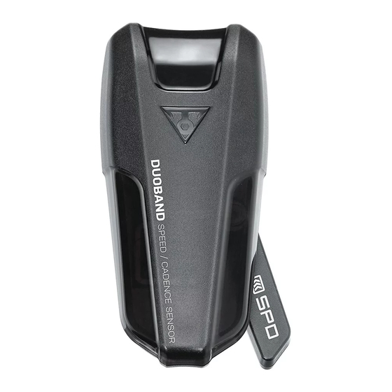
DUOBAND
Sync to PanoBike App and other Apps with
Bluetooth® Smart (BLE 4.0) connection program.
Sensing Indicator
Green Light
Blinking
50 times
Low Batter
Indicator
Red Light
Blinking
50 times
INSTALLATION
TIPS : Proper distance between Sensor and Magnet : < 10 mm
1
Cadence Magnet Set (A)
O
P
3 mm
T
I
O
N
A
Cadence Magnet Set (B)
O
P
T
I
O
N
B
Install Cadence Magnet on left crankarm near pedal as
shown. Do not tighten zip ties completely to allow
magnet placement.
2
Pre-fit Sensor and Rubber Bracket on left rear
chainstay (non-drive side) and trim excess rubber
from bracket. Insure the Topeak logo is facing up.
Install zip ties loosely to allow sensor placement.
SPEED & CADENCE SENSOR
Speed Sensor
Sensing Point
Cadence Sensor
Sensing Point
Cadence
Magnet
3
Unscrew the wheel magnet to
install on spoke.
Tighten the Wheel Magnet onto spoke and align with sensing point on sensor.
ANT+ system for Garmin or other devices.
Cadence Magnet Set (A)
Cadence Magnet Set (B)
for pedal axle hexagon socket
Rubber Pad
Cadence Magnet
Cadence Magnet
12 x 3 mm
Top View
Cadence Sensor
Sensing Point
Cadence
Magnet
For Round Spokes
For Bladed Spokes
User's Guide
Speed Magnet Set
for crankarm
Rubber Bracket Set
Holder
Zip Tie
Rubber
Bracket
IMPORTANT NOTE
Align Cadence Magnet with
Cadence Sensor Sensing
Point as shown to insure
magnet does not interfere
with Speed Sensor.
Top View
Cadence Sensor
Sensing Point
IMPORTANT NOTE
Align Cadence Magnet with Cadence Sensor
Sensing Point as shown to insure magnet
does not interfere with Speed Sensor.
Top View
Speed Sensor
Sensing Point
IMPORTANT NOTE
Align Wheel Magnet with Speed
Sensor Sensing Point as shown
to insure magnet does not
interfere with Cadence Sensor.
EN
Zip Tie
Advertisement
Table of Contents

Related Manuals for Topeak DUOBAND


Summary of Contents for Topeak DUOBAND
- Page 1 Pre-fit Sensor and Rubber Bracket on left rear Sensor Sensing Point as shown chainstay (non-drive side) and trim excess rubber from bracket. Insure the Topeak logo is facing up. to insure magnet does not Install zip ties loosely to allow sensor placement.
- Page 2 This equipment complies with FCC radiation exposure limits set forth for an uncontrolled environment Please contact your Topeak dealer with any questions. For USA customer service, This transmitter must not be colocated or operating in conjunction with any other antenna or transmitter.
Need help?
Do you have a question about the DUOBAND and is the answer not in the manual?
Questions and answers