Table of Contents
Advertisement
Quick Links
Advertisement
Table of Contents
Troubleshooting

Related Manuals for Tektronix 2215A


Summary of Contents for Tektronix 2215A
- Page 2 SAFETY SUMMARY AND THE SERVICE SAFETY SUMMARY PRIOR TO PERFORMING ANY SERVICE. Tektronix National Marketing Center for Product Order Information, contact your local Tektronix sales representative or, in the U.S., call 1-800-426-2200 ext 41 In Oregon call collect (503)627-9000 ext 41 Tektronix National Marketing Center P.O.
- Page 3 Copyright © 1983 Tektronix, Inc. All rights reserved. Contents of this publication may not be reproduced in any form without the written permission of Tektronix, Inc. Products of Tektronix, Inc. and its subsidiaries are covered by U.S. and foreign patents and/or pending patents. TEKTRONIX, TEK, SCOPE-MOBILE, and registered trademarks of Tektronix, Inc.
-
Page 4: Table Of Contents
2215A Service TABLE OF CONTENTS Page Page SECTION 3 THEORY OF OPERATION (cont) LIST OF ILLUSTRATIONS ........LIST OF TABLES ............CHANNEL SWITCH AND OPERATORS SAFETY SUMMARY ......VERTICAL OUTPUT ....3-5 SERVICING SAFETY SUM M ARY......TRIGGER AMPLIFIERS AND SWITCHING ......... - Page 5 2215A Service TABLE OF CONTENTS (cont) Page Page MAINTENANCE SECTION 6 MAINTENANCE (cont) SECTION 6 STATIC-SENSITIVE COMPONENTS INTERCONNECTIONS ....6-10 PREVENTIVE MAINTENANCE..TRANSISTORS AND INTRODUCTION ......INTEGRATED CIRCUITS .... 6-11 GENERAL CARE ......SOLDERING TECHNIQUES 6-12 REMOVAL AND REPLACEMENT INSPECTION AND CLEANING . .
-
Page 6: List Of Tables
............and EXT INPUT connectors ....... Multi-connector holder orientation .... 1- 2 Physical dimensions of the 2215A Oscilloscope........... Color codes for resistors and capacitors. Voltage, power cord, and fuse data ....Semiconductor lead configurations. Fuse holder and power cord connector . . . -
Page 7: Operators Safety Summary
2215A Service OPERATORS SAFETY SUMMARY The general safety information in this p a rt o f the summary is for both operating and servicing personnel. Specific warnings and cautions w ill be found throughout the manual where they apply and do not appear in this summary. -
Page 8: Servicing Safety Summary
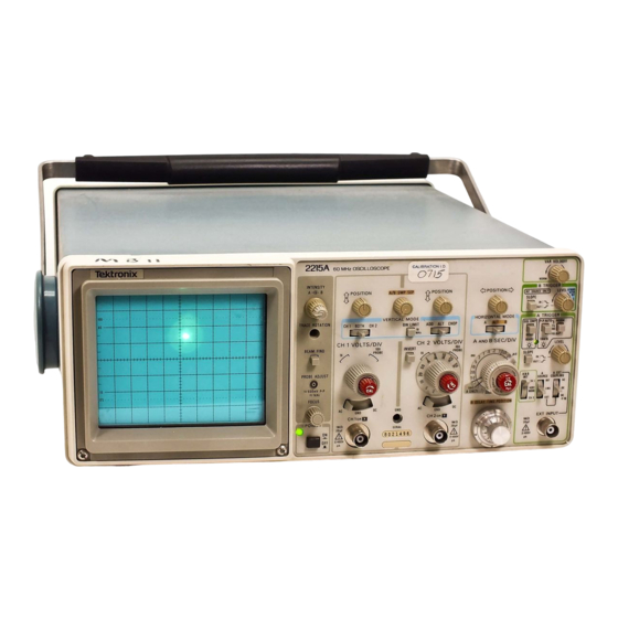
2215A Service SERVICING SAFETY SUMMARY FOR QUALIFIED SERVICE PERSONNEL ONLY Refer also to the preceding Operators Safety Summary. Disconnect power before removing protective panels, sol Do Not Service Alone dering, or replacing components. Do not perform internal service or adjustment of this prod... - Page 9 2215A Service 4735-01 The 2215A Oscilloscope.
-
Page 10: Specification
The following electrical characteristics (Table 1-1) are valid for the 2215A when it has been adjusted at an ambient temperature between + 20°C and +30°C , has had a warm up period of at least 20 minutes, and is operating at an ambient temperature between 0°C and +50°C (unless oth... - Page 11 Specification— 2215A Service Table 1-1 Electrical Characteristics Characteristics Performance Requirements Supplemental Information VERTICAL DEFLECTION SYSTEM Deflection Factor 5 mV per division to 5 V per division gain is adjusted with VOLTS/DIV switch Range 2 mV per division to 5 V per division set to 10 mV per division.
- Page 12 Specification— 2215A Service Table 1-1 (cont) Performance Requirements Supplemental Information Characteristics VERTICAL DEFLECTION SYSTEM (cont) See Figure 1-1 for derating curve. Maximum Safe Input Voltage A 400 V (dc + peak ac) or 800 V ac p-p DC Coupled to 10 kHz or less.3...
- Page 13 Specification— 2215A Service Table 1-1 (cont) Characteristics Performance Requirements Supplemental Information TRIGGER SYSTEM (cont) LEVEL Control Range A TRIGGER (NORM) Can be set to any point of the trace that can be displayed.8 At least ±1.6 V, 3.2 V p-p.
- Page 14 Specification— 2215A Service Table 1-1 (cont) Characteristics Performance Requirements Supplemental Information HORIZONTAL DEFLECTION SYSTEM (cont) Differential Time Measurement Exclude delayed operation when A and B Accuracy SEC/DIV knobs are locked together at any sweep speed or when a SEC/DIV ±1 % +0.015 major dial division + 15°C to +35°C...
- Page 15 Specification— 2215A Service Table 1-2 Environmental Characteristics Description Characteristics NOTE The instrument meets the requirements o f MIL-T-28800C, paragraphs 4.5.5.1.3, 4.5.5.1.4, and 4.5.5.1.2.2 for Type III, Class 5 equipment, except where other wise noted. Temperature Operating 0°C to + 50°C (+ 3 2 °F to +122°F).
-
Page 16: And Ext Input Connectors
Specification— 2215A Service Table 1-3 Physical Characteristics Characteristics Description Weight With Power Cord With Cover, Probes, and Pouch 6.2 kg (13.7 lb). Without Cover, Probes, and Pouch 5.2 kg (11.5 lb). Domestic Shipping Weight 7.3 kg (16.0 lb). Height With Feet and Handles 137 mm (5.4 in). -
Page 17: Physical Dimensions Of The 2215A
Specification—2215A Service Di me n si o n s are in i nches [ m m ] 4735-40 Figure 1-2. Physical dimensions of the 2215A Oscilloscope. -
Page 18: Operating Instructions
Am erican 120V NEM A 5-15-P 1 2 0 V / considerations pertaining to the use of the 2215A. Before IEC 83 connecting the instrument to a power source, carefully read Universal the following about line voltages, power cords, and fuses. -
Page 19: Instrument Cooling
POWER M AX WATTS 4 0 M AX VA 70 FREQ 4 8 4 4 0 to TEKTRONIX. INC . BEAVERTON. OREGON. U S A POWER CORD Figure 2-2. Fuse holder and power cord connector. CONTROLS, CONNECTORS, AND INDICATORS The following descriptions are intended to familiarize the M j)P R O B E ADJUST Connector—... -
Page 20: Vertical
Operating Instructions— 2215A Service C4732-03 Figure 2-3. Power and display controls and indicators and PROBE ADJUST output. VERTICAL R efer to Figure 2-4 fo r location o f item s 9 through 17. ( j P ) CH 1 VO LTS/D IV and CH 2 VO LTS /D IV Sw itches—... -
Page 21: Horizontal
Operating Instructions— 2215A Service Input Coupling (AC-GND-DC) Switches— Three-po A Trigger system to approximately 10 MHz. Button © sition switches that select the method of coupling the must be pressed a second time to release it and regain full 60 MHz bandwidth operation. Provides a input signals to the instrument deflection system. -
Page 22: Trigger
Operating Instructions— 2215A Service Figure 2-5. Horizontal controls. ) HORIZONTAL MODE Switch— Three-position switch Sweep and the start of the B Sweep. Delay time is determines the mode of operation for the horizontal variable from 0.5 times to 10 times the A SEC/DIV deflection system. -
Page 23: Trigger Controls, Connector, And Indicator
Operating Instructions— 2215A Service IN— When button is pressed in, sweep is triggered from the negative-going slope of the trigger signal. (2 9 ) A SOURCE Switch— Determines the source of the trigger signal that is coupled to the input of the A Trig... -
Page 24: Rear Panel
Operating Instructions— 2215A Service ® A EXT COUPLING Switch— Determines the method used to couple external signals to the A TRIGGER circuit from the EXT INPUT connector. AC— Signals above 60 Hz are capacitively coupled to the input of the A Trigger circuit. Any dc compo... -
Page 25: Operating Considerations
ICULE g r a t MARKE the 2215A and the unit under test are connected by a com mon reference (ground lead), in addition to the signal lead or probe. The probe's ground lead provides the best grounding method for signal interconnection and ensures the maxi... -
Page 26: Operator S Adjustments
Operating Instructions— 2215A Service 3. Connect the probe tip to the signal source and wait level difference is more than 10 times the VOLTS/DIV several seconds for the input coupling capacitor to charge. switch setting: 1. Set the Input Coupling switch to GND. -
Page 27: Probe Compensation
Operating Instructions— 221 Service should not be required. If adjustment is needed, perform the Set the A SEC/DIV switch to display several cycles of following procedure: the PROBE ADJUST signal. Use the Channel 1 POSITION control to vertically center the display. 1. -
Page 28: Theory Of Operation
Section 3— 2215A Service THEORY OF OPERATION INTRODUCTION INTEGRATED CIRCUIT DESCRIPTIONS SECTION ORGANIZATION This section of the manual contains a general summary of instrument functions followed by a detailed description of Digital Logic Conventions each major circuit. A basic block diagram, a detailed block... -
Page 29: General Description
When reading this general circuit description o f the tained from the ac power line to develop the gate signal for 2215A Oscilloscope, refer to the basic block diagram the A Sweep Generator. The B Trigger circuitry uses only (Figure 9-4) and to the detailed block diagram (Figure the Internal Trigger signal to gate the B Sweep Generator. -
Page 30: Detailed Circuit Description
Theory of Operation— 2215A Service The Dc Restorer circuit applies the output voltage of the The Alternate B Sweep circuitry controls the Alt and Z-Axis Amplifier between the cathode and grid of the crt. B Horizontal mode displays and includes the B Miller Sweep High dc potentials on these elements prohibit direct coupling Generator and B Sweep Logic circuitry. -
Page 31: Vertical Preamplifiers
Theory of Operation— 2215A Service Paraphase Amplifier Input Coupling The signal applied to the CH 1 OR X input connector can The Paraphase Amplifier converts the single-ended sig be ac coupled, dc coupled, or disconnected from the input of nal from the Gain Switching Network into a differential sig... -
Page 32: Channel Switch And Vertical Output
Theory of Operation— 2215A Service produce differential output current to drive the Delay Line Driver. Internal trigger signals for the Trigger circuitry are picked-off and channel selection for crt display is controlled by the Channel Switch circuitry. FROM CHANNEL 1 ATTENUATOR Common-base transistors Q102 and Q103 convert dif... - Page 33 Theory of Operation— 2215A Service differential amplifier composed of Q230 and Q231 with low- Coupling capacitor C547 and resistors R547 and R548 form a differentiating circuit that produces positive- and neg and high-frequency compensation provided by the RC net ative-going short-duration pulses. These pulses are inverted works connected between the emitters.
-
Page 34: Trigger Amplifiers And Switching
Theory of Operation— 2215A Service TRIGGER AMPLIFIERS AND SWITCHING CHANNEL 1. For triggering from Channel 1, the A&B INT switch is set to CH 1. The XY line connected to S555 will be at ground potential and one input of U555B will be held LO The Trigger Amplifiers, shown on Diagram 3, provide sig... -
Page 35: A Trigger Generator
Theory of Operation—2215A Service The CHOP VERTICAL MODE position grounds the Line Trigger Amplifier V Mode T line and places a LO on an input of both U555B The Line Trigger Amplifier supplies a line-frequency trig and U555C. The outputs of these two gates will then be LO... -
Page 36: A Sweep Generator And Logic
Theory of Operation— 2215A Service by the A TRIGGER LEVEL control. Positive or negative When TV Field is not selected, the TV Trig Enable line slope triggering is selected by the A TRIGGER SLOPE connected to R402 and R473 is LO. Transistors Q402 and switch. - Page 37 Theory of Operation—2215A Service The Sweep Logic circuitry controls the holdoff time, the timing resistors varies with the rotational position of starts the sweep upon reception of a trigger signal, and ter R721, the SEC/DIV Variable control. A fixed dc voltage is minates the sweep at the proper sweep level.
-
Page 38: Alternate B Sweep
Theory of Operation— 2215A Service the Intensity and Z-Axis circuits to establish the crt lease U506A from the set condition. The circuit is then en unblanking and intensity levels needed for producing both abled to generate another sweep once a trigger signal is again applied to the clock input of U506A. - Page 39 Theory of Operation— 2215A Service B Delay Time Position Comparator line goes from HI to_LO to change the U680C-U680D flip-flip output states. The R input of U670A will then be LO, caus The B Delay Time Position Comparator circuit compares ing the Q output to be HI and reset the Generator.
-
Page 40: Horizontal
Theory of Operation— 2215A Service signal is NANDed with the Alt Sync signal by U680A to flection plates. Signals applied to the Horizontal Preamplifier clock U670B. Whenever the Alt Sync signal goes LO at the can come from either the A or the B Miller Sweep Generator... -
Page 41: Z-Axis Amplifier
Theory of Operation— 2215A Service FROM A SWEEP GENERATOR FROM B SWEEP GENERATOR FROM ALTERNATE D IS P LA Y SW ITCHING LOG IC TO CRT H O R IZ DEFLECTIO N PLATES FROM A TRIGGER FROM A S E C /D IV... - Page 42 Theory of Operation— 2215A Service For an X-Y display, CR818, CR817, and CR816 are re impedance termination for the input signals and isolates the verse biased. The XY signal is LO to reverse bias CR551 signal sources from following stages of the Z-Axis Amplifier.
-
Page 43: Power Supply And Probe Adjust
Theory of Operation— 2215A Service Figure 3-5. Simplified diagram of the Dc Restorer circuitry. the crt writing-beam current toward the new intensity level. During the positive transitions of the ac drive, from the The Dc Restorer output level then follows the Z-Axis output- lower clamped level toward the higher clamped level, the charge on C854 increases due to the rising voltage. - Page 44 Theory of Operation— 2215A Service CR902, CR903, and CR904. The bridge full-wave rectifies approximately 1 A. When the voltage across C940 reaches the source voltage, and the output is filtered by C906. Input approximately 43 V, the voltage amplifier starts controlling...
- Page 45 Theory of Operation— 2215A Service the crt cathode. The — 2 kV supply is filtered by a low-pass When the instrument is first turned on, one of the switch filter composed of C975, C976, R976, R978, and C979. ing transistors will start to conduct and its collector voltage Neon lamp DS870 protects against excessive voltage be...
-
Page 46: Performance Check Procedure Introduction
Section 4— 2215A Service PERFORMANCE CHECK PROCEDURE INTRODUCTION PURPOSE TEST EQUIPMENT The “Performance Check Procedure" is used to verify the The test equipment listed in Table 4-1 is a complete list of Performance Requirement statements listed in Table 1-1. It the equipment required to accomplish both the “Perfor... -
Page 47: Preparation For Checks
Performance Check Procedure—2215A Service PREPARATION FOR CHECKS Before performing any procedure in this section, set the POWER switch to ON and allow a 20-minute warm-up period. It is not necessary to remove the instrument cover to accomplish any subsection in the “ Performance Check Pro... -
Page 48: Index To Performance Check Steps
Performance Check Procedure— 2215A Service Table 4-1 (cont) Item No. and Minimum Examples of Suitable Description Specification Purpose Test Equipment 6. Dual-Input Coupler Connectors: BNC-Female-to- Vertical checks and Tektronix Part Number 067- Dual-BNC male. adjustments 0525-01. 7. 10X Attenuator Ratio: 10X. Impedance: 50 fi. -
Page 49: Deflection Accuracy Limits
Performance Check Procedure— 2215A Service VERTICAL Equipment Required (see Table 4-1): Calibration Generator (Item 1) 50-0 BNC Termination (Item 5) Dual-Input Coupler (Item 6) Leveled Sine-Wave Generator (Item 2) 10X Attenuator (Item 7) 50-0 BNC Cable (Item 4) INITIAL CONTROL SETTINGS 1 VOLTS/DIV Variable control to the CAL detent and con... -
Page 50: Settings For Bandwidth Checks
Performance Check Procedure— 2215A Service e. Disconnect the test equipment from the instrument. b. Connect the leveled sine-wave generator output via a 50-52 cable and a 50-52 termination to the CH 2 OR Y input connector. 4. Check Common-Mode Rejection Ratio a. - Page 51 Performance Check Procedure— 2215A Service o. CHECK— Display amplitude is 0.6 division or less. c. Set the generator to produce a 25-MHz, 5-division display. p. Disconnect the test equipment from the instrument. d. Set the VERTICAL MODE switch to CH 2.
-
Page 52: Horizontal
Performance Check Procedure— 2215A Service HORIZONTAL Equipment Required (see Table 4-1): Calibration Generator (Item 1) 50-0 BNC Cable (Item 4) Leveled Sine-Wave Generator (Item 2) 50-0 BNC Termination (Item 5) Time-Mark Generator (Item 3) INITIAL CONTROL SETTINGS LEVEL Midrange A&B INT... -
Page 53: Settings For Timing Accuracy Checks
Performance Check Procedure—2215A Service Use the Horizontal POSITION control to align the first Table 4-4 time marker that is 25 ns beyond the start of the sweep with Settings for Timing Accuracy Checks the second vertical graticule line. Time-Mark Generator Setting SEC/DIV CHECK—... -
Page 54: Settings For Delay Time Accuracy Checks
Performance Check Procedure— 2215A Service Table 4-5 CHECK— Intensified portion of the trace starts within 0.5 division of the start of the sweep. Settings for Delay Time Accuracy Checks Time-Mark A SEC/DIV B SEC/DIV Rotate the B DELAY TIME POSITION control fully... - Page 55 Performance Check Procedure— 2215A Service 50-ns Select time markers from the time-mark CHECK— Start of the sweep can be positioned to the generator. right of the center vertical graticule line by rotating the Hori zontal POSITION control fully clockwise. Rotate the B DELAY TIME POSITION control counter...
-
Page 56: Trigger
Performance Check Procedure— 2215A Service TRIGGER Equipment Required (see Table 4-1): Leveled Sine-Wave Generator (Item 2) 50-fi BNC Termination (Item 5) 50-fi BNC Cable (Item 4) INITIAL CONTROL SETTINGS b. Set the generator to produce a 5-MHz, 3-division display. Vertical c. - Page 57 Performance Check Procedure— 2215A Service i. Repeat parts d through f. e. Set CH 1 VOLTS/DIV switch to 50 mV. j. Set: f. Set the leveled sine-wave generator output voltage to 150 mV and the frequency to 60 MHz. Set the X I0 Magni...
- Page 58 Performance Check Procedure—2215A Service f. Press in the SGL SWP RESET button several times. c. Press in the SGL SWP RESET button. The READY LED should illuminate and remain on. d. Set the Channel 1 Input Coupling switch to DC.
-
Page 59: External Z-Axis And Probe Adjust
Performance Check Procedure— 2215A Service EXTERNAL Z-AXIS AND PROBE ADJUST Equipment Required (see Table 4-1): Leveled Sine-Wave Generator (Item 2) BNC T-Connector (Item 8) Two 50-0 BNC Cables (Item 4) 10X Probe (provided with instrument) 50-0 BNC Termination (Item 5) INITIAL CONTROL SETTINGS nector. -
Page 60: Adjustment Procedure
Section 5— 2215A Service ADJUSTMENT PROCEDURE INTRODUCTION PURPOSE ments, it is important that test equipment used for making these checks meet or exceed the specifications described in Table 4-1. When considering use of equipment other than The "Adjustment Procedure” is a set of logically se... -
Page 61: Adjustment Interactions
Adjustment Procedure— 2215A Service partial adjustment might otherwise be required. Only change place instructions located in the ‘ Maintenance’ section of an internal adjustment setting if a Performance Characteris the manual. tic cannot be met with the original setting. If it is necessary to change the setting of an internal adjustment, check Table 5-1 for possible adjustment interactions. -
Page 62: Index To Adjustment Procedure Steps
Adjustment Procedure— 2215A Service INDEX TO ADJUSTMENT PROCEDURE Horizontal Page STEPS 1. Adjust Horizontal Amplifier Gain ......5-13 2. Adjust X I0 Horizontal Amplifier Gain ....5-14 3. Adjust Magnifier Registration ......5-14 Power Supply and CRT Display Page 4. Check Position R a n g e ......... -
Page 63: Power Supply And Crt Display
Adjustment Procedure—2215A Service POWER SUPPLY AND CRT DISPLAY Equipment Required (See Table 4-1): Leveled Sine-Wave Generator (Item 2) Digital Voltmeter (Item 10) Time-Mark Generator (Item 3) DC Voltmeter (Item 12) 50-0 BNC Cable (Item 4) Screwdriver (Item 13) 50-0 BNC Termination (Item 5) ADJUSTMENT LOCATIONS S I a t th e b a c k o f th is m a n u a l fo r lo c a tio n o f te s t p o in ts a n d a d ju stm e n ts. - Page 64 Adjustment Procedure— 2215A Service 2. Check High-Voltage Supply c. Set the generator to produce a 50-kHz, 4-division display. d. ADJUST— Astig (R874) and the front-panel FOCUS W A R M I N G control for the best defined waveform. In s tru m e n t m u s t b e tu rn e d o f f w hen re m o vin g o r re ...
-
Page 65: Vertical
Adjustment Procedure— 2215A Service VERTICAL Equipment Required (See Table 4-1): Calibration Generator (Item 1) 10X Attenuator (Item 7) Leveled Sine-Wave Generator (Item 2) Adapter (Item 9) 50-ft BNC Cable (Item 4) Screwdriver (Item 13) 50-ft BNC Termination (Item 5) Low-Capacitance Alignment Tool (Item 14) - Page 66 Adjustment Procedure— 2215A Service Position the trace on the center horizontal graticule c. Set the INVERT button to On (button in). line using the Channel 2 POSITION control. ADJUST— Ch 2 Invert Bal (R75) to set the trace to the c.
- Page 67 Adjustment Procedure— 2215A Service h. ADJUST— Ch 1 MF/LF Comp (C3) and Ch 1 MF/LF VOLTS/DIV switch. If trace shift is observed, repeat Step 2 Gain Bal (R47) for the best front corner and flat top. of this procedure. i. Disconnect the test equipment from the instrument.
- Page 68 Adjustment Procedure— 2215A Service Table 5-4 Set the calibration generator to produce a 20-mV Attenuator Compensation Adjustments signal. Channel 2 Adjustment Channel 1 c. Set the bottom of the signal on the center horizontal graticule line using the Channel 2 POSITION control.
- Page 69 Adjustment Procedure— 2215A Service s. Repeat parts c through q for Channel 2. 12. Adjust High-Frequency Compensation (C237) and Delay Line Com pensation (R240 and R241) a. Set: t. Disconnect the test equipment from the instrument. VERTICAL MODE CH 1...
- Page 70 Adjustment Procedure— 2215A Service c. CHECK— Display amplitude is 4.2 divisions or greater m. Set the CH 2 VOLTS/DIV switch to 5 mV. as the generator output frequency is increased up to the value shown in Table 5-5 for the corresponding VOLTS/DIV switch setting.
- Page 71 Adjustment Procedure—2215A Service CHECK— Display amplitude is 0.05 division or less. Adjust the CH 1 or CH 2 VOLTS/DIV Variable control for minimum display amplitude. Disconnect the test equipment from the instrument. I. Set the VERTICAL MODE switch to CH 1.
-
Page 72: Horizontal
Adjustment Procedure— 2215A Service HORIZONTAL Equipment Required (see Table 4-1): Calibration Generator (Item 1) 50-fi BNC Termination (Item 5) Leveled Sine-Wave Generator (Item 2) Test Oscilloscope (Item 11) Time-Mark Generator (Item 3) Screwdriver (Item 13) 50-12 Cable (Item 4) Low-Capacitance Alignment Tool (Item 14) - Page 73 Adjustment Procedure— 2215A Service d. CHECK— The 11th time marker can be positioned to Adjust X10 Horizontal Amplifier Gain (R754) the left of the center vertical graticule line by rotating the a. Set: Horizontal POSITION control fully counterclockwise. HORIZONTAL MODE...
- Page 74 Adjustment Procedure— 2215A Service ADJUST— Delay Start (R646) so that the 2nd A- A SEC/DIV 0.05 Sweep time marker is intensified and the B-Sweep time X I0 Magnifier On (knob out) marker's rising edge starts at the beginning of the B Sweep.
- Page 75 Adjustment Procedure— 2215A Service Use the Horizontal POSITION control to align the first Table 5-6 time marker that is 25 ns beyond the start of the sweep with Settings for Timing Accuracy Checks the second vertical graticule line. Time-Mark Generator Setting SEC/DIV CHECK—...
- Page 76 Adjustment Procedure— 2215A Service Align the start of the A Sweep with the 1st vertical p. Set: graticule line using the Horizontal POSITION control. A SEC/DIV B SEC/DIV B DELAY TIME POSITION 1.00 CHECK— Intensified portion of the trace starts within 1.1 divisions of the start of the sweep.
- Page 77 Adjustment Procedure—2215A Service d. CHECK— Display is at least 3.5 horizontal divisions. 12. Adjust X Gain (R760) a. Set: e. Disconnect the test equipment from the instrument. CH 1 VOLTS/DIV 10 mV A SEC/DIV 14. Check A -S w eep Holdoff b.
-
Page 78: Trigger
Adjustment Procedure— 2215A Service TRIGGER Equipment Required (see Table 4-1): Leveled Sine-Wave Generator (Item 2) 10X Attenuator (Item 7) 50-fi BNC Cable (Item 4) Digital Voltmeter (Item 12) 50-!i BNC Termination (Item 5) Screwdriver (Item 13) Dual-Input Coupler (Item 6) ADJUSTMENT LOCATIONS 1 a t th e b a c k o f th is m a n u a l fo r te s t p o in ts a n d a d ju s tm e n t locations. - Page 79 Adjustment Procedure— 2215A Service b. Connect the leveled sine-wave generator output via a b. Set the generator to produce a 50-kHz, 5-division 50-52 cable and a 50-52 termination to the CH 1 OR X input display. connector. c. Set the CH 1 VOLTS/DIV switch to 0.5 V.
- Page 80 Adjustment Procedure— 2215A Service g. Set: c. Set the leveled sine-wave generator output voltage to 40 mV and the frequency to 5 MHz. VERTICAL MODE CH 2 HORIZONTAL MODE A&B INT CH 2 d. CHECK— Stable display can be obtained by adjusting the A TRIGGER LEVEL control for each switch combination given in Table 4-6.
- Page 81 Adjustment Procedure— 2215A Service 8. Check Single Sweep Operation e. CHECK— READY LED goes out and a single sweep occurs. a. Adjust the A TRIGGER LEVEL control to obtain a sta ble display. NOTE b. Set: The A INTENSITY control may require adjustment to observe the single-sweep trace.
-
Page 82: External Z-Axis And Probe Adjust
Adjustment Procedure— 2215A Service EXTERNAL Z-AXIS AND PROBE ADJUST Equipment Required (see Table 4-1): Leveled Sine-Wave Generator (Item 2) BNC T-Connector (Item 8) Two 50-!) BNC Cables (Item 4) 10X Probe (provided with instrument) 50-fi BNC Termination (Item 5) INITIAL CONTROL SETTINGS... -
Page 83: Maintenance
Section 6— 2215A Service MAINTENANCE This section of the manual contains information for conducting preventive maintenance, troubleshooting, and corrective maintenance on the 2215A Oscilloscope. STATIC-SENSITIVE COMPONENTS The following precautions are applicable when perform Pick up components by their bodies, never by their ing any maintenance involving internal access to the leads. -
Page 84: Preventive Maintenance
Overheating usually indicates other mild detergent with 95% water. Before using any trouble in the instrument; therefore, it is more important that other type o f cleaner, consult your Tektronix Service the cause of overheating be corrected to prevent recurrence Center or representative. - Page 85 Maintenance— 2215A Service Table 6-2 External Inspection Checklist Repair Action Item Inspect For Touch up paint and replace defective parts. Cracks, scratches, deformations, and damaged Cabinet and Front hardware or gaskets. Panel Repair or replace missing or defective items. Missing, damaged, or loose knobs, buttons, and Front-panel Controls controls.
-
Page 86: Lubrication
Maintenance— 2215A Service CLEANING. To clean the interior, blow off dust with dry, low-pressure air (approximately 9 psi). Remove any remain ing dust with a soft brush or a cloth dampened with a solu tion of mild detergent and water. A cotton-tipped applicator Use only hot deionized o r distilled water, 55°... -
Page 87: Troubleshooting
Maintenance— 2215A Service vealed or corrected by readjustment. If only a partial adjust Complete Performance Check and Adjustment instruc ment is performed, see the interaction chart, Table 5-1, for tions are given in Sections 4 and 5. The Performance Check Procedure can also be helpful in localizing certain trouble in possible adjustment interactions with other circuits. -
Page 88: Troubleshooting Equipment
Guide. This chart will help identify a particular problem area stripes identifies three digits of the Tektronix Part Number, for further troubleshooting. using the resistor color-code system (e.g., a diode having... - Page 89 Maintenance— 2215A Service 3. Visual Check Perform a visual inspection. This check may reveal bro ken connections or wires, damaged components, semi conductors not firmly mounted, damaged circuit boards, or other clues. W A R N I N G Dangerous potentials exist at several points through...
- Page 90 Maintenance—2215A Service 6-4 are based on a system limited in bandwidth to 30 kHz panel control settings, and cable-connection instruc tions. The control-setting changes (from initial setup) (greater bandwidth will result in higher readings). required to obtain the given waveforms and voltages are located on the waveform-diagram page.
- Page 91 Checks on diodes can be per mance Check Procedure" and “Adjustment Procedure" formed in much the same manner as on transistor (Sections 4 and 5) and to Table 5-1 (Adjustment emitter-to-base junctions; use a dynamic tester, such Interactions). as the TEKTRONIX 576 Curve Tracer.
-
Page 92: Corrective Maintenance
If it is necessary to mechanical parts used in this instrument were manufactured ship your instrument to a Tektronix Service Center for repair by Tektronix, Inc. Order all special parts directly from your or service, refer to the “ Repackaging for Shipment"... -
Page 93: Transistors And Integrated Circuits
Maintenance— 2215A Service Table 6-5 Maintenance Aids Example Description Specifications Usage Antex Precision Model C. General soldering and 1. Soldering Iron 15 to 25 W. unsoldering. Torx tips #T7, #T9, #T10, Assembly and disassembly. Tektronix Part Numbers 2. Torx Screwdrivers (#T7) 003-1293-00 #T15 and #T20. -
Page 94: Soldering Techniques
Use rosin-core wire solder containing 63% tin and 37% proceeding to the next pin. lead. Contact your local Tektronix Field Office or represen tative to obtain the names of approved solder types. When soldering on circuit boards or small insulated Excessive heat can cause the etched circuit conduc... -
Page 95: Removal And Replacement Instructions
Maintenance— 2215A Service component is replaced while the board is installed in the Pull the front panel and attached chassis forward and instrument, cut the leads so they protrude only a small out of the cabinet. amount through the reverse side of the circuit board. Excess lead length may cause shorting to other conductive parts. - Page 96 Maintenance— 2215A Service Remove the screw from the plastic power-supply Unplug the crt anode lead connector from the High- cover on the bottom section of the Main circuit board. Press Voltage Multiplier lead located on left side of Power-Supply gently on the rear of the cover and slide it forward.
- Page 97 Maintenance— 2215A Service Filter Circuit Board Resolder the 27 pins to the Main circuit board (unsol dered in step 1). To remove the Filter circuit board, perform the following steps: Remove the Power-Supply shield (see the "Power- Supply Shield” removal procedure).
- Page 98 Maintenance— Service 2215A To reinstall the Attenuator circuit board, perform the fol Lock the A and B SEC/DIV knobs together and note lowing steps: the position for reinstallation reference. Use a 1/4-inch nut driver to remove the nut securing the B SEC/DIV knob; pull Insert the two VOLTS/DIV switch shafts and the Input off the knob and collet from the shaft assembly.
- Page 99 Maintenance— 2215A Service Reinstall the collet and the B SEC/DIV knob at the Complete reinstallation of the module by performing position noted in step 2 and secure it with the nut. steps 12 through 17 of the “Attenuator Circuit Board”...
- Page 100 Maintenance— 2215A Service NOTE Resolder the resistor to the EXT INPUT center con nector and the wire strap to the EXT INPUT ground lug A t this p o in t, a n y c o m p o n e n t o n th e F ro n t-P a n e l cir...
- Page 101 Maintenance— 2215A Service 7. Remove the POWER switch extension-shaft assem 16. Use a vacuum-desoldering tool to unsolder the 39 bly by first pressing in the POWER button to the ON posi wire straps (connecting the Main circuit board to the Front- tion.
-
Page 102: Repackaging For Shipment
10 MHz 750 pF 5 MHz REPACKAGING FOR SHIPMENT 3300 pF 1 MHz If the instrument is to be shipped to a Tektronix Service 0.068 50 kHz Center for service or repair, attach a tag showing: owner 0.33 10 kHz... -
Page 103: Options
Section 7— 2215A Service OPTIONS There are currently no options for the 2215A, except the optional power cords previously described in Section 2. -
Page 104: Replaceable Electrical Parts
Each diagram and circuit board illustration is clearly marked with the assembly number Changes to Tektronix instruments are sometimes made to Assembly numbers are also marked on the mechanical exploded accommodate improved components as they become available, views located in the Mechanical Parts List. - Page 105 Replaceable Electrical Parts—2215A Service CROSS INDEX— MFR. CODE NUMBER TO MANUFACTURER Address Mfr. Code Manufacturer City, State, Zip 7625 BUSH LAKE RD 000FG RIFA WORLD PRODUCTS INC. P.O. BOX 35263 MINNEAPOLIS, MN 55435 TOPTRON CORP TOKYO, JAPAN 000LI P.O. BOX 3608 00779 AMP.
- Page 106 Replaceable Electrical Parts—2215A Service CROSS INDEX— MFR. CODE NUMBER TO MANUFACTURER City. State, Zip___________ Mfr. Code Manufacturer Address________________________ 22 COLUMBIA ROAD MORRISTOWN. NJ 07960 ELECTRA-MIDLAND CORP.. MEPCO DIV. 80031 STANDARD GRIGSBY CO., DIV. OF SUN 82104 CHEMICAL CORPORATION 920 RATHBONE AVENUE AURORA.
- Page 107 Replaceable Electrical Parts—2215A Service Tektronix Serial/Model No. Component No. Part No. Dscont Name & Description_____________ Code Mtr Part Number ASSEMBLIES 670-8284-00 B010100 B011899 CKT BOARD ASSY:MAIN 80009 670-8284-00 670-8284-01 B011900 80009 670-8284-01 CKT BOARD ASSY:MAIN 672-008600 672-0086-00 CKT BOARD ASSY:ATTENUATOR...
- Page 108 Replaceable Electrical Parts—2215A Service Tektronix Serial/Model No. Dscont Name & Description Code Mfr Part Number Component No. Part No. GC70-1E102M CAP. .FXD.CER 01:0.001 UP, + 80-20%. 100V 04222 A1C369 281-0862-00 CAP..FXD.MICA D:16.8PF. + /-0.5PF.500V 00853 D155C16R8D0 A1C381 283-0663-00 CAP..FXD.CER DI:0.1UF,20%.50V...
- Page 109 Replaceable Electrical Parts—2215A Service Serial/Model No. Tektronix Name & Description Code Mfr Part Number Dscont Component No. Part No. 04222 GC70-1E102M 281-0862-00 CAP..FXD.CER Dl:0.001 UF,+80-20%. 100V A1C648 04222 GC70-1 El 02M CAP..FXD.CER DI:0.001UF, + 80-20%, 100V A1C649 281-0862-00 8035D9AADC0G150K 72982 281-0797-00 CAP..FXD.CER DI:15PF.10%,100V...
- Page 110 Replaceable Electrical Parts—2215A Service Tektronix Serial/Model No. Name & Description Code Mfr Part Number Part No. Dscont Component No. CAP.,FXD,ELCTLT:840UF.10 + 100%.12V 90201 VPR841N012E1E1C 290-0945-00 A1C968 CAP.,FXD,ELCTLT:840UF, 10 + 100%,12 V 90201 VPR841N012E1E1C 290-0945-00 A1C970 430P582 285-1255-00 CAP.,FXD,PLASTI:0.01UF,20%,3KV 56289 A1C975...
- Page 111 Replaceable Electrical Parts—2215A Service Tektronix Serial/Model No. Mfr Part Number Component No. Part No. Dscont Code Name & Description A1CR946 12969 UTR308 152-0414-00 SEMICOND DEVICE:SILICON,200V,0.75A A1CR947 12969 UTR308 152-0414-00 SEMICOND DEVICE:S1LICON,200V,0.75A A1CR954 UTR307 152-0413-00 SEMICOND DEVICE:SILICON.400V,750MA 12969 UTR307 A1CR955 152-0413-00 SEMICOND DEVICE:SILICON.400V,750MA...
- Page 112 Replaceable Electrical Parts—2215A Service Tektronix Serial/Model No. Component No. Part No. Mfr Part Number Name & Description Code Dscont A1Q285 151-0712-00 TRANSISTOR:SILICON,NPN 04713 SPS8223 A1Q302 151-0711-01 TRANSISTOR: NPN,SI,TO-92 04713 SPS8608M A1Q303 151-0711-01 TRANSISTOR:NPN,SI.TO-92 04713 SPS8608M A1Q327 151-0711-01 SPS8608M TRANSISTOR:NPN,St,TO-92 04713...
- Page 113 Replaceable Electrical Parts—2215A Service Serial/Model No. Tektronix Mfr Part Number Component No. Part No. Dscont Name & Description Code 321-0155-00 RES..FXD,FILM:402 OHM.1%.0.125W 91637 MFF1816G402R0F A1R102 91637 MFF1816G402R0F A1R103 321-0155-00 RES..FXD.FILM:402 OHM.1%.0.125W A1R104 91637 MFF1816G110R0F 321-0101-00 RES.,FXD,FILM:110 OHM.1%,0.125W A1R105 321-0101-00 RES..FXD.FILM: 110 OHM.1 %,0.125W...
- Page 114 Replaceable Electrical Parts—2215A Service Serial/Model No. Tektronix Component No. Part No. Dscont Name & Description Code Mfr Part Number A1R204 321-0089-00 RES..FXD.FILM:82.5 OHM,1%,0.125W 91637 MFF1816G82R50F RES.,FXD.FILM:274 OHM.1%,0.125W 91637 MFF1816G274R0F A1R206 321-0139-00 A1R207 RES..FXD.FILM:274 OHM,1%.0.125W 91637 MFF1816G274R0F 321-0139-00 A1R210 315-0331-00 RES.,FXD.CMPSN:330 OHM.5%,0.25W...
- Page 115 Replaceable Electrical Parts—2215A Service Serial/Model No. Tektronix Mfr Part Number Name & Description Code Dscont Component No. Part No. CB4315 RES.,FXD,CMPSN:430 OHM.5%.0.25W 01121 315-0431-00 A1R289 91637 MFF1816G715R0F 321-0179-00 RES.,FXD,FILM:715 OHM.1%,0.125W A1R292 CB6205 RES..FXD,CMPSN:62 OHM.5%,0.25W 01121 A1R293 315-0620-00 RES..FXD,CMPSN:220 OHM.5%,0.25W 01121...
- Page 116 Replaceable Electrical Parts—2215A Service Tektronix Serial/Model No. Name & Description Code Mfr Part Number Component No. Part No. Dscont RES.,FXD.CMPSN:910 OHM,5%,0.25W 01121 CB9115 A1R367 315-0911-00 RES.,FXD,CMPSN:750 OHM,5%,0.25W 01121 CB7515 A1R369 315-0751-00 01121 CB2205 A1R372 315-0220-00 RES.,FXD,CMPSN:22 OHM,5%,0.25W 01121 CB2025 A1R374 315-0202-00 RES.,FXD,CMPSN:2K OHM,5%,0.25W...
- Page 117 Replaceable Electrical Parts—2215A Service Tektronix Serial/Model No. Dscont Name & Description Code Mfr Part Number Component No. Part No. A1R464 RES.,FXD,CMPSN:270 OHM,5%,0.25W 01121 CB2715 315-0271-00 RES.,FXD.CMPSN:430 OHM,5%,0.25W 01121 CB4315 A1R465 315-0431-00 01121 CB8205 A1R469 315-0820-00 RES.,FXD,CMPSN:82 OHM,5%,0.25W RES..FXD,CMPSN:11K OHM,5%.0.25W 01121...
- Page 118 Replaceable Electrical Parts—2215A Service Tektronix Serial/Model No. Name & Description Code Mfr Part Number Dscont Component No. Part No. 01121 CB5115 RES.,FXD,CMPSN:510 OHM,5%,0.25W A1R566 315-0511-00 CB3325 RES.,FXD,CMPSN:3.3K OHM,5%,0.25W 01121 A1R568 315-0332-00 01121 CB4325 315-0432-00 RES.,FXD,CMPSN:4.3K OHM,5%,0.25W A1R569 01121 CB2225 A1R571 315-0222-00 RES.,FXD,CMPSN:2.2K OHM,5%,0.25W...
- Page 119 Replaceable Electrical Parts—2215A Service Tektronix Serial/Model No. Mfr Part Number Dscont Name & Description Code Component No. Part No. RES.,FXD,CMPSN:3K OHM.5%,0.25W 01121 CB3025 A1R818 315-0302-00 CB3325 A1R820 315-0332-00 RES.,FXD.CMPSN:3.3K OHM,5%,0.25W 01121 A1R822 301-0512-00 RES.,FXD,CMPSN:5.1K OHM,5%,0.50W 01121 EB5125 301-0512-00 RES.,FXD,CMPSN:5.1K OHM,5%,0.50W...
- Page 120 Replaceable Electrical Parts—2215A Service Tektronix Serial/Model No. Mfr Part Number Component No. Dscont Name & Description Code Part No. RES.,FXD,CMPSN:30K OHM.5%.0.25W 01121 CB3035 A1R921 315-0303-00 01121 CB2035 A1R922 RES.,FXD.CMPSN:20K OHM.5%.0.25W 315-0203-00 01121 CB1245 RES.,FXD.CMPSN:120K OHM,5%,0.25W A1R925 315-0124-00 GB1545 RES.,FXD.CMPSN:150K OHM,5%,1W...
- Page 121 Replaceable Electrical Parts—2215A Service Tektronix Serial/Model No. Component No. Part No. Dscont Name & Description Code Mfr Part Number A 1U 506 1 56 -1639-00 M IC R O C IR C U IT .D I:E C L ,D U A L D M A -S L A V E FF...
- Page 122 Replaceable Electrical Parts—2215A Service Tektronix Serial/Model No. Component No. Name & Description Code Mfr Part Number Part No. Dscont A1W954 131-0566-00 BUS CONDUCTOR:DUMMY RES,2.375,22 AWG 57668 JWW-0200E0 A1W955 131-0566-00 BUS CONDUCTOR:DUMMY RES,2.375,22 AWG 57668 JWW-0200E0 A1W956 BUS CONDUCTOR:DUMMY RES,2.375,22 AWG...
- Page 123 Replaceable Electrical Parts—2215A Service Serial/Model No. Tektronix Part No. Dscont Component No. Name & Description Code Mfr Part Number A2 ATTENUATOR 672-0086-00 CKT BOARD ASSY:ATTENUATOR 80009 672-0086-00 A2AT1 307-1014-06 ATTENUATOR.FXD: 10OX 80009 307-1014-06 A2AT2 307-1013-00 ATTENUATOR,FXD:10X 80009 307-1013-00 307-1014-06 A2AT51...
- Page 124 Replaceable Electrical Parts—2215A Service Tektronix Serial/Model No. Dscont Description Component No. Name & Code Mfr Part Number Part No. A2P9108 TERMINAL,PIN',0.365 L X 0.025 PH BRZ GOLD 48283-036 131-0608-00 22526 (QUANTITY OF 4) A2P9200 131-0787-00 TERMINAL.PIN:0.64L X 0.025 SQ 22526...
- Page 125 Replaceable Electrical Parts—2215A Service Tektronix Serial/Model No. Dscont Name & Description Code Mfr Part Number Component No. Part No. A2R57 315-0160-00 RES.,FXD,CMPSN:16 OHM,5%,0.25W 01121 CB1605 RES.,FXD.CMPSN:22 OHM,5%.0.25W 01121 CB2205 A2R58 315-0220-01 RES.,FXD,CMPSN:1.1K OHM,5%,0.25W 01121 CB1125 A2R59 315-0112-00 RES.,VAR,NONWIR:10K OHM,20%,0.50W 73138...
- Page 126 Replaceable Electrical Parts—2215A Service Tektronix Serial/Model No. Mfr Part Number Name & Description Code Component No. Part No. Dscont A3 FRONT PANEL CKT BOARD ASSYtFRONT PANEL 80009 670-8286-00 670-8286-00 0841545Z5V00203Z 283-0006-00 CAP.,FXD,CER DI:0.02UF,+ 80-20%,500V 59660 A3C376 CAP..FXD.CER DI:11PF,5%,500V 59660 • 301 -OOOCOGO110J...
- Page 127 Replaceable Electrical Parts—2215A Service Serial/Model No. Tektronix Part No. Dscont Component No. Name & Description Code Mfr Part Number A3S226 260-2075-00 SWITCH,PUSH:SPDT.50VDC.500M AMP 80009 260-2075-00 260-2033-00 A3S380 SWITCH,SUDE:DPTT,125V,0.5A 82389 ORD BY DESCR A3S390 260-2111-00 SWITCH,PUSH:1 BUTTON,1 POLE,BEAM FIND 59821 ORD BY DESCR...
- Page 128 Replaceable Electrical Parts—2215A Service Tektronix Serial/Model No. Component No. Part No. Dscont Name & Description Code Mfr Part Number A4 TIMING 670-8285-00 CKT BOARD ASSY:TIMING 80009 670-8285-00 A4C701 295-0194-00 CAP SET,MATCHED:2 EA 1.0UF,1.5%,50V 90201 TTX 100 + 100 A4C702 283-0674-00 CAP.,FXD,MICA D:85PF.1%,500V...
- Page 129 Replaceable Electrical Parts—2215A Service Tektronix Serial/Model No. Mfr Part Number Dscont Name & Description Code Component No. Part No. TRANSiSTOR:SILICON,NPN 04713 SPS8246 151-0424-00 A4Q701 22229 S2089 A4Q704 151-1042-00 SEMICOND DVC SE:MATCHED PAIR FET 04713 SPS8317 151-0736-00 TRANSISTOR:SILICON,NPN A4Q706 04713 SPS8246...
- Page 130 Replaceable Electrical Parts—2215A Service Tektronix Serial/Model No. Code Mfr Part Number Name & Description Component No. Part No. Dscont 80009 155-0124-00 155-0124-00 MICROCIRCUIT,LlrHORIZONTAL PREAMPL A4U760 1N747A SEMICOND DEVICE:ZEN,SI,3.6V,5%,0.4W 04713 A4VR720 152-0744-00 SEMICOND DEVICE:ZEN,SI,3.6V,5%,0.4W 04713 1N747A A4VR749 152-0744-00 57668 JWW-0200E0 BUS CONDUCTOR:DUMMY RES,2.375,22 AWG...
- Page 131 Replaceable Electrical Parts—2215A Service Tektronix Serial/Model No. Component No. Part No. Dscont Name & Description Code Mfr Part Number A5 ALTERNATE SWEEP 670-8287-00 CKT BOARD ASSY:ALTERNATE SWEEP 80009 670-8287-00 281-0862-00 A5C610 CAP..FXD.CER DL0.001UF,+80-20%,100V 04222 GC70-1E102M A5C624 281-0826-00 CAP..FXD.CER DI:2200PF.5%,100V 12969...
- Page 132 Replaceable Electrical Parts—2215A Service Tektronix Serial/Model No. Dscont Name & Description Code Mfr Part Number Component No. Part No. A5R642 RES.,FXD,FILM:18.2K OHM,1%,0.125W 91637 MFF1816G18201F 321-0314-00 RES.,FXD,FILM:22.1K OHM,1%,0.125W 91637 MFF1816G22101F A5R643 321-0322-00 RES.,FXD,CMPSN:5.1K OHM,5%,0.25W A5R644 01121 CB5125 315-0512-00 RES.,FXD,FILM:7.5K OHM,1%,0.125W 91637...
- Page 133 Replaceable Electrical Parts—2215A Service Tektronix Serial/Model No. Mfr Part Number Dscont Name & Description Code Part No. Component No. A6 EMI FILTER CKT BOARD ASSY:EMI FILTER BOARD 80009 670-7615-00 670-7615-00 D5243 FI 772-415-2000 285-1252-00 CAP.FXD,PLASTIC:0.15UF,10%,250VAC A6C900 CAP.,FXD,PPR DI:0.0022UF,20%.250VAC 000FG PME271Y422...
- Page 134 Capacitors = Values one or greater are in picofarads (pF). Values less than one are in microfarads Other ANSI standards that are used in the preparation of diagrams by Tektronix, Inc. are: Resistors = Ohms (O). The inform ation and special symbols below may appear in this manual.
- Page 135 COLOR CODE ® and © - 1 st, 2nd, and 3rd significant figures —multiplier —tolerance — temperature coefficient © ( ? ) and/or ^ c ) color code may not be present © —polarity and voltage rating on some capacitors COLOR RESISTORS CAPACITORS...
- Page 136 711 & Q254-255 256-257 PLASTIC METAL CASE CASE TRANSISTORS TRANSISTORS TRANSISTOR INTEGRATED CIRCUITS LEAD CONFIGURATIONS AND CASE STYLES ARE TYPICAL, BUT MAY VARY DUE TO VENDOR CHANGES OR INSTRUMENT MODIFICATIONS. (3826-17)4206-32A Figure 9-2. Semiconductor lead configurations.
-
Page 137: Diagrams
2215A S e rvice identify component Locate the Circuit Board Illustration 2. Determine the C ircuit Number 3. Locate th e C om ponent on the S chem atic Diagram mounted on a circuit board and to locate that component in the... - Page 138 2215A Service 4735-04 Figure 9-4. Basic block diagram.
- Page 140 2215A Service TEST WAVEFORM AND VOLTAGE SETUPS WAVEFORM MEASUREMENTS DC VOLTAGE MEASUREMENTS On the left-hand pages preceding the schematic dia Typical voltage measurements, located on the schematic grams are test waveform illustrations that are intended to diagram, were obtained with the instrument operating under the conditions specified in the Waveforms Measurements aid in troubleshooting the instrument.
- Page 141 POWER SUPPLY ISOLATION PROCEDURE Each regulated supply has numerous feed points to ex If a power supply comes up after lifting one of the main ternal loads throughout the instrument. The power distribu jumpers from the power supply to isolate that supply, it is tion diagram is used in conjunction with the schematic very probable that a short exists in the circuitry on that sup...
- Page 142 CHASSIS M OUNTED PARTS CIRCUIT SCHEM SCHEM CIRCUIT SCHEM SC H EM NUMBER NUMBER LOCATION NUMBER NUMBER LOCATION D L 9 2 1 0 P9 870-1 P 9 8 7 0 -2 D S 9 1 5 0 P 9 8 7 0 -3 P 9 8 7 0 -4 F9001 P 9 8 7 0 -5...
- Page 143 W9001 (A1 TO A3) DIAG NO. DIAG NO. & GRID WIRE & GRID WIRE COORDINATES LINE NAME COORDINATES LINE NAME 6.3B HORIZ POS BEAM FIND 7.4F 3.8M +AUTO LEVEL CW CH 1 POS CW 2,2D 3.8M -AUTO LEVEL CCW 2,3D CH 1 POS CCW 4,8B A/B SWP SEP...
- Page 144 W9705 (A1 TO A4) P970S (A4 TO A1) DIAG NO. OIAG NO. & GRID & GRID WIRE LINE NAME COORDINATES LINE NAME COORDINATES 8.3N 6,9E 6,5L +SWP +SWP 6,5K 6,7L 6.7K -SWP -SWP 8,3N 6,9E 6,4E X AXIS SIG X AXIS SIG 6,4E 8,3N 6,9E...
- Page 145 CIRCUIT BCARD \N TER CONNECTIONS 2 2 1 5 A 4 7 5 5 - 2 0...
- Page 146 2215A Service Static Sensitive Devices See Maintenance Section COMPONENT NUMBER EXAMPLE Component Number A23 A2 R1234 Schemju Assembly N um b* Ore* Svbissembty Number Number (it used) C hassism ounted com ponents have no Assem bly Num ber prefci—see end ot Replaceable B ectnal Parts List...
-
Page 147: A2-Attenuator Board
A 2 — A T TE N U A T O R B O A R D CIRCUIT CIRCUfT CIRCUIT SCHEM SCHEM CIRCUIT SCHEM SCHEM NUMBER NUMBER NUMBER NUMBER NUMBER NUMBER NUMBER NUMBER AT51 AT52 CR18 CR57 CR68 P9103-1 P9103-2 P9103-3 P9103-4 P9108-1... - Page 148 CH 1 & CH 2 A T T E N U A T O R S < 1 ASSEMBLY A2 SCHEM BOARD SCHEM BOARD CIRCUIT SCHEM BOARD CIRCUIT CIRCUIT SCHEM BOARD CIRCUIT LOCATION LOCATION LOCATION LOCATION NUMBER LOCATION NUMBER LOCATION LOCATION NUMBER NUMBER...
- Page 149 ► ► C H I^ C H Z ATTENUATOR'S <£> 22I5A 4>n&-z\...
- Page 150 Service G __________ I ■ 5 -8 -10 C281-, W9870 C226. '-:R22^ TP537 U225 U537 ^C R 1 8 3 ~ C 7 8 ^> CR764 - U130 VR78&9 Q780 ’ R782 R796-. W978J v CR823 -H5E&-* *-{R780- : W975 \-C R 8 2 6 f W979 J C832 .
- Page 151 A1 —M AIN BOARD SCHEM CIRCUIT SCHEM SCHEM CIRCUIT SCHEM CIRCUIT SCHEM CIRCUIT SCHEM CIRCUIT CIRCUIT NUMBER NUMBER NUMBER NUMBER NUMBER NUMBER NUMBER NUMBER NUMBER NUMBER NUMBER NUMBER R262 Q202 R130 C l 14 C547 CR393 R266 CR399 Q203 R131 C l 15 C553 R267...
- Page 152 A 1 —MAIN BOARD (cont) SCHEM CIRCUIT SCHEM CIRCUIT SCHEM SCHEM CIRCUIT CIRCUIT SCHEM CIRCUIT SCHEM CIRCUIT NUMBER NUMBER NUMBER NUMBER NUMBER NUMBER NUMBER NUMBER NUMBER NUMBER NUMBER NUMBER T948 W 494 W9001-3 R392 R826 R525 W9001-4 R828 TP397 W 535 R393 R526 W9001-5...
- Page 154 2215A Service C O N T R O L S E T T I N G S 2 2 1 5 DC Voltages Input Coupling (both) VOLTS/DIV (both) 0.1V AC Waveforms VERTICAL MODE BOTH, CHOP A TRIGGER Mode P-P AUTO 0 .4 p s...
- Page 155 VERTICAL PREAMP & OUTPUT AMPL < 2 ASSEMBLY A1 CIRCUIT SCHEM BOARD CIRCUIT SCHEM BOARD CIRCUIT SCHEM BOARD CIRCUIT SCHEM BOARD NUM BER LOCATION NUM BER LOCATION LOCATION NUM BER LOCATION LOCATION NUMBER LOCATION LOCATION LOCATION C l 14 Q 2 5 4 R 286 R189 Q 2 5 5...
- Page 156 VERTICAL PREAMP & OUTPUT AM PL < 2 (cont) ASSEMBLY A3 CIRCUIT SCHEM BOARD CIRCUIT SCHEM BOARD CIRCUIT SCHEM BOARD BOARD CIRCUIT SCHEM LOCATION NUMBER LOCATION LOCATION LOCATION LOCATION LOCATION NUMBER LOCATION LOCATION NUMBER NUMBER W534 W9000-8 CR534 R162 W9000-10 W9000-9 CR537 R201...
- Page 157 Z 2 .I5 A...
- Page 158 4. 7 JS -Z2.
- Page 159 2215A Service C ______ i _______ D ______ , _____ E Figure 9-9. A3—Front Panel board. Static Sensitive Devices See Maintenance Section COMPONENT NUMBER EXAMPLE Component Number A 2 3 A 2 R1234 Schemata Assembly L _ * Circuit Number...
-
Page 160: A3-Front Panel Board
A 3 — F R O N T PANEL B O A R D SCHEM SCHEM CIRCUIT SCHEM CIRCUIT CIRCUIT NUMBER NUMBER NUMBER NUMBER NUMBER NUMBER C376 R520 W9000-14 C377 R602 W9000-15 R726 W9000-16 C379 C380 R982 W9000-17 W9000-18 C987 R983 CR534 R985... - Page 161 TRIGGERING < 3 ASSEMBLY A1 CIRCUIT SCHEM BOARD CIRCUIT SCHEM BOARD SCHEM BOARD CIRCUIT SCHEM BOARD CIRCUIT LOCATION LOCATION LOCATION NUMBER LOCATION LOCATION NUMBER LOCATION LOCATION NUMBER LOCATION NUMBER R393 R565 C363 R306 C369 R307 R395 R309 R399 TP397 C381 R402 TP460 C389...
- Page 162 TRIGGERING < 3 (cont) ASSEMBLY A3 CIRCUIT CIRCUIT SCHEM BOARD CIRCUIT SCHEM BOARD SCHEM BOARD CIRCUIT SCHEM BOARD LOCATION NUMBER LOCATION LOCATION NUMBER LOCATION LOCATION NUM BER. LOCATION LOCATION NUMBER LOCATION W 9000 -33 R377 W 539 C376 W 9000 -34 R378 W 630 C377...
- Page 163 ► ► ► ► *■ ► NUMERAL AND UTTER AT SIGNAL LINES TO OR FROM OTHER DIAGRAMS WOICATCS THE GRIO COORDINATES ON ANOTHER SCHEMATIC (FOR EXAMPLE. 4E) T R IG G E R IN G <§> 22.15 A...
- Page 164 2215A Service Q 7 0 6 (3 7 0 1 P r m r r S Ob K ~ ) © ^ ^ jC705y 7 ‘ ■ C P '*- CM (N r- r- 4735-17 Figure 9-11. A4—Timing board. COMPONENT NUMBER EXAMPLE...
- Page 165 A4—TIMING BOARD SCHEM CIRCUIT SCHEM CIRCUIT SCHEM CIRCUIT NUMBER NUMBER NUMBER NUMBER NUMBER NUMBER C701 P 9700-7 R721 C701 P 9700-8 R722 R724 C701 P 9 7 00 -8 P 9700-9 R727 C701 R728 C702 P9705-1 P 9705-2 R730 C703 R731 C705 P 9705-3...
- Page 166 2215A CONTROL SETTINGS DC Voltages A INTENSITY M id ra n g e HORIZONTAL MODE A SEC/DIV 0 .1 A TRIGGER Mode P-P AUTO AC Waveforms CH 1 VERTICAL MOOE CH 1 VOLTS/DIV CH 1 In p o t C o u p lin g...
- Page 167 A S W E E P G E N E R A T O R & L O G IC < 4 ASSEMBLY A1 CIRCUIT SCHEM CIRCUIT SCHEM BOARD CIRCUIT CIRCUU SCHEM BOARD BOARD SCHEM BOARD LOCATION LOCATION LOCATION NUMBER NUMBER LOCATION LOCATION...
- Page 168 ► ► 2 2 I 5 A 473S-Z*...
- Page 169 2215A Service 2215A CONTROL SETINGS DC Voltages AC Waveforms In p u t VERTICAL MODE CH 1 C o u p lin g ( b o t h ) CH 1 VOLTS/DIV In p u t C o u p lin g...
- Page 170 Figure 9-12. A5—Alternate Sweep board. Static Sensitive Devices S e e M s in te n e n c e S e c tio n COMPONENT NUMBER EXAMPLE Component Number A5—ALTERNATE A23 A2 R1234 SWEEP BOARD Schematic A ssem bly Circuit N u m b e r S ubessem bly...
- Page 171 A 5 — A L T E R N A T E S W E E P B O A R D SCHEM CIRCUIT SCHEM CIRCUIT SCHEM CIRCUIT SCHEM CIRCUIT NUMBER NUMBER NUMBER NUMBER NUMBER NUMBER NUMBER NUMBER W 6 7 7 C610 R623 U605...
- Page 172 B T IM IN G & A L T E R N A T E B S W E E P < 5 (cont) ASSEMBLY A3 CIRCUIT ORCUIT SCHEM BOARD SCHEM BOARD CIRCUIT SCHEM BOARD SCHEM BOARD CIRCUIT LOCATION NUMBER LOCATION NUMBER LOCATION...
- Page 173 2 215 A. B TIMING £ A LT E R N A T E B SWEEP <S>...
- Page 174 2215A Service 2215A CONTROL SETTINGS DC Voltages In p u t C o u p lin g ( b o t h ) HORIZONTAL MODE A TRIGGER Mode P-P AUTO AC Waveforms In p u t C o u p lin g...
- Page 175 P R O B E A D J U S T , X Y A M P L IF IE R & H O R IZ O N T A L O U T P U T < 6 ASSEMBLY A1 BOARD CIRCUIT SCHEM...
- Page 177 2215A Service Figure 9-13. A6—Filter board. A 6 — FILTER B O A R D SCHEM CIRCUIT SCHEM CIRCUIT NUMBER NUMBER NUMBER NUMBER C900 T901 T903 C902 VR901 C903 W9011 R900 W9041 R901 R903 W9091 RT901 W9191 Static Sensitive Devices See Maintenance Section A6—FILTER BOARD...
-
Page 178: Oscilloscope
POWER SUPPLY WAVEFORMS DC Voltages AC Waveforms P re re g u la to r and in v e r te r v o lta g e s are WARNING re fe re n c e d to te s t p o in t noted a d ja ce n t to the v o lta g e . - Page 179 2215A CONTROL SETTINGS AC Woveforms CH 1 V E R T IC A L MODE CH 1 V O L T S /D IV 5» V I n p u t C o u p l i n g HORIZO NTAL MODE...
- Page 180 POWER SUPPLY, Z AXIS & CRT < 7 (cont) ASSEMBLY A1 (cont) CIRCUIT SCHEM BOARD CIRCUIT SCHEM CIRCUIT SCHEM BOARD CIRCUIT SCHEM BOARD BOARD LOCATION LOCATION NUMBER LOCATION NUMBER LOCATION LOCATION NUMBER LOCATION NUMBER LOCATION LOCATION R925 Q944 R858 TP950 R926 Q946 R860...
- Page 181 •» *• » » > ► AXIS $ CRT <£>...
- Page 182 POW ER D IS T R IB U T IO N < 8 ASSEMBLY A1 BOARD CIRCUIT SCHEM BOARD CIRCUIT SCHEM BOARD CIRCUIT SCHEM LOCATION LOCATION NUMBER LOCATION LOCATION NUMBER LOCATION LOCATION NUMBER W 993 C200 TP961 W 995 C201 W 997 C220 W 408...
- Page 183 W 9 5 5 —•— •— a)<$> m oo v L < 3 > +ioovB,)<§> W954 W959 P199 1 r _Q Q W 9TC XT IoT g ? G ND • T O < $ > W 9 * 7 0 5 W 954>...
- Page 184 2215A Service C 237 R240 PEAK R 874 R 8 70 C 0M P 1 COMP ASTIG GEOM 4735-31 A1— MAIN BOARD ADJUSTMENT LOCATIONS...
- Page 185 GAIN COMP COMP 100X COM P 100X INPUT C 100X COM P C 54 100X INPUT C C 62 CH 2 CH 2 CH 2 CH 2 M F /L F 2 /5 -m V INPUT C M F /L F 2-m V COMP GAIN...
- Page 186 C 7 1 3 R 7 30 R 7 40 HIGH B SWEEP A SWEEP SPEED GAIN GAIN T IM IN G R749 REGIS R 754 C 703 GAIN HIGH SPEED TIM ING A4—TIM ING BOARD ADJUSTMENT LOCATIONS...
- Page 187 R 65 2 DELAY 4735-34 A 5 — A L T E R N A T E S W E E P B O A R D A D J U S T M E N T L O C A T IO N S...
- Page 188 GENERAL NOTES A. Use s c h e m a tic d ia g r a m s , th e o v e r o l l b lo c k d ia g ro m > c i r c u i t b o a rd I l l u s t r a t i o n s ) ond c i r c u i t d e s c r ip t i o n s when o n o ly z ln g in s tr u m e n t m a lf u n c t io n s and lo c a t i n g t e s t p o i n t s .
- Page 189 2215A S e rvice 4735-11...
-
Page 190: Section 10 Replaceable Mechanical Parts
If a part you have ordered has been replaced with a new or Parts o l D etail Part improved part, your local Tektronix, Inc. Field Office or Attaching parts lor Parts o l Detail Part representative will contact you concerning any change in part number. - Page 191 Replaceable Mechanical Parts—2215A Service CROSS INDEX— MFR. CODE NUMBER TO MANUFACTURER Address City, State, Zip Mfr. Code Manufacturer P.O. BOX 3608 HARRISBURG. PA 17105 00779 AMP, INC. 01536 CAMCAR DIV OF TEXTRON INC. SEMS PRODUCTS UNIT 1818 CHRISTINA ST. ROCKFORD, IL 61108...
- Page 192 Replaceable Mechanical Parts— 2215A Service Fig. & Index Tektronix Serial/Model No. Part No._____ Eff_______ Dscont 1 2 3 5______ Name & Description_______________ Code Mfr Part Number M A R K E R ,ID E N T rM A R K E O C A U T IO N...
- Page 194 2215A SERVICE...
- Page 195 ^ 5 )
- Page 196 Replaceable Mechanical Parts—2215A Service Fig. & Index Tektronix Serial/Model No. Part No. Dscont 1 2 3 4 5 Name & Description Code Mfr Part Number 334-5002-00 PLATE,IDENT:MKD TEKTRONIX 80009 334-5002-00 426-1765-00 FRAME,CRT: 80009 426-1765-00 211-0690-01 SCREW,MACHINE:6-32 X 0.875.PNH.SST.TORX ORD BY DESCR...
- Page 197 Replaceable Mechanical Parts—2215A Service Fig. & Index Tektronix Serial/Model No. No._____ Part No._____ Eff_______ Dscont 1 2 3 4 5______ Name & Description_______________ Code Mfr Part Number 02768 207-080501-00 2-52 BUTTON,PLUG:0.187 DIA,NYLON 134-0158-00 S3629 FEK 031 1666 CAP.,FUSEHOLDER:3AG FUSES 200-2264-00...
- Page 198 Replaceable Mechanical Parts—2215A Service Fig. & Index Tektronix Serial/Model No. Part No. Dscont 1 2 3 4 5 Name & Description Code Mfr Part Number 80009 334-4251-00 334-4251-00 MARKER,IDENTiMKD CAUTION 337-2773-00 SHIELD,ELEC:POWER SUPPLY,LOWER.PLSTC 80009 337-2773-00 211-0305-00 01536 ORD BY DESCR SCREW,MACHINE:4-40 X 0.437,PNH...
- Page 199 Replaceable Mechanical Parts—2215A Service Fig. & Index Tektronix Serial/Model No. Code Mfr Part Number Part No. Dscont 1 2 3 4 5 Name & Description 48283-036 22526 ..TERMINAL,PIN:0.365 L X 0.025 PH BRZ GOLD 131-0608-00 3-39 22526 47359 ..TERMINAL,PIN:0.64L X 0.025 SQ...
- Page 201 Replaceable Mechanical Parts— 2215A Service Fig. & Index Tektronix Serial/Model No. Part No. Dscont 1 2 3 4 5 Name & Description Code Mfr Part Number STANDARD ACCESSORIES 0 7 0 -4 7 3 2 -0 0 M A N U A L ,T E C H :O P E R A T O R S .2 2 1 5 A...
- Page 202 2215A SERVICE...
-
Page 203: Change Information
MANUAL CHANGE IN FO R M A TIO N At Tektronix, we continually strive to keep up with latest electronic developments by adding circuit and component improvements to our instruments as soon as they are developed and tested. Sometimes, due to printing and shipping requirements, we can’t get these changes immediately into printed manuals. - Page 204 Tfektronix MANUAL c h a n g e in fo r m a tio n Date:_____ 6-6-84_________ Change Reference:____ C1/0684_______ com mitted to excellence Product: 2215A SERVICE Manual Part No, 070-4735-00 DESCRIPTION PG 46 EFFECTIVE ALL SERIAL NUMBERS TEXT CHANGES Page 5-19—...
- Page 205 000-2775-00D...
- Page 206 Tektronix MANUAL CHANGE INFORMATION C1/0684(REV) 8-10-84 Change Reference: Date: COMMITTED TO EXCELLENCE 070-4735-00 Product: ggl5A SERVICE Manual Part No.:__ PG 46 DESCRIPTION EFFECTIVE ALL SERIAL NUMBERS TEXT CHANGES Page 5-19— 5-20 Step 2. Replace 2. Adjust Trigger Sensitivity (R479) and (R627) with the following procedure.
Need help?
Do you have a question about the 2215A and is the answer not in the manual?
Questions and answers