Table of Contents
Advertisement
Advertisement
Chapters
Table of Contents

Related Manuals for Tektronix 2213A


Summary of Contents for Tektronix 2213A
- Page 1 Tektronix- 2213A OSCILLOSCOPE OPERATORS INSTRUCTION MANUAL...
-
Page 2: Table Of Contents
2213A Operators TABLE OF CONTENTS Page Section 3 OPERATORS FAMILIARIZATION (cont) LIST OF ILLUSTRATIONS ........LIST OF TABLES ............. INPUT COUPLING CAPACITOR OPERATORS SAFETY SUMMARY ......PRECHARGING ......OPERATOR’S ADJUSTMENTS ..Section 1 GENERAL INFORMATION INTRODUCTION ......BASELINE TRACE ...... - Page 3 The 2213A Oscilloscope ............................Maximum input voltage vs frequency derating curve for CH 1 OR X, CH 2 OR Y, and EXT INPUT connectors .. 1- 2 Physical dimensions of the 2213A Oscilloscope....................2- 1 Optional power c o rd s ............................
-
Page 4: Operators Safety Summary
2213A Operators OPERATORS SAFETY SUMMARY The general safety information in this part o f the summary is for both operating and servicing personnel. Specific warnings “ J and cautions will be found throughout the manual where they apply and do not appear in this summary. -
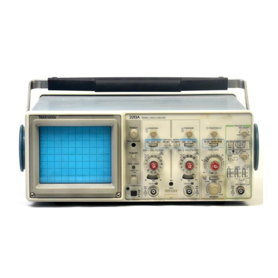
Page 5: The 2213A Oscilloscope
2213A Operators The 2213A Oscilloscope. -
Page 6: General Information
The following electrical characteristics (Table 1-1) are mance characteristics for which no absolute limits are speci valid for the 2213A when it has been adjusted at an ambient fied, or characteristics that are impractical to check. temperature between +20°C and +30°C, has had a warm... - Page 7 General Information— 2213A Operators Table 1-1 Electrical Characteristics Characteristics Performance Requirements Supplemental Information VERTICAL DEFLECTION SYSTEM Deflection Factor 5 mV per division to 5 V per division gain is adjusted with VOLTS/DIV switch Range 2 mV per division to 5 V per division set to 10 mV per division.
-
Page 8: Common-Mode Rejection
General Information— 2213A Operators Table 1-1 (cont) Supplemental Information Characteristics Performance Requirements VERTICAL DEFLECTION SYSTEM (cont) Common-Mode Rejection Ratio At least 20 to 1 at 25 MHz. Checked at 10 mV per division for (CMRR) common-mode signals of 6 divisions or less with VOLTS/DIV Variable control adjusted for best CMRR at 50 kHz. - Page 9 General Information— 2213A Operators Table 1-1 (cont) Characteristics Performance Requirements Supplemental Information HORIZONTAL DEFLECTION SYSTEM Sweep Rate 0.5 s per division to 0.05 ns per division in a 1-2-5 sequence. X I0 magnifier extends maximum sweep speed to 5 ns per division.
- Page 10 General Information— 2213A Operators Table 1-1 (cont) Characteristics Performance Requirements Supplemental Information PROBE ADJUST Output Voltage of PROBE ADJUST 0.5 V ±5%. Jack 1 kHz ±20%. Repetition Rate Z-AXIS INPUT Sensitivity 5 V causes noticeable modulation. Useable frequency range is Positive-going input decreases d c to 10 MHz.
- Page 11 General Information— 2213A Operators Table 1-2 Environmental Characteristics ___________________________________________________________________ £ Description Characteristics NOTE The instrument meets the requirements o f MIL-T-28800C, paragraphs 4.5.5.1.3, 4.5.5.1.4, and 4.5.5.1.2.2 for Type III, Class 5 equipment, except where other wise noted. Temperature 0°C to +50°C (+32°F to +122°F).
- Page 12 General Information— 2213A Operators Table 1-3 Physical Characteristics Characteristics Description Weight With Power Cord With Cover, Probes, and Pouch 6.0 kg (13.1 lb). Without Cover, Probes, and Pouch 5.0 kg (10.9 lb). Domestic Shipping Weight 7.0 kg (15.4 lb). Height With Feet and Handles 137 mm (5.4 in).
-
Page 13: Physical Dimensions Of The 2213A Oscilloscope
General Information— 2213A Operators Figure 1-2. Physical dimensions of the 2213A Oscilloscope. ADD DEC 1983... -
Page 14: Calibration
A more frequent interval may be necessary if your REPACKAGING FOR SHIPMENT If the instrument is to be shipped to a Tektronix Service Surround the instrument with polyethylene sheeting to Center for service or repair, attach a tag showing; owner protect its finish. -
Page 15: First-Time Start Up
A N S I C 7 3 .1 1 A m erican 1 2 0 V N E M A 5 -1 5 -P considerations pertaining to the use of the 2213A. Before 1 2 0 V / IEC 83 1 5 A connecting the instrument to a power source, carefully read the following about line voltages, power cords, and fuses. -
Page 16: Instrument Cooling
Preparation For Use— 2213A Operators INSTRUMENT COOLING LINE FUSE Always maintain adequate instrument cooling. The venti lation holes on both sides of the instrument cabinet and on the rear panel must remain free of obstruction. CAUTION CAUTION TO AVOID ELECTRIC SHOCK. -
Page 17: Controls, Connectors, And Indicators
Preparation For Use— 2213A Operators CONTROLS, CONNECTORS, AND INDICATORS The following descriptions are intended to familiarize the H j j PROBE ADJUST Connector— Provides an approxi- operator with the location, operation, and function of the mately 0.5 V, negative-going, square-wave voltage (at instrument’s controls, connectors, and indicators. -
Page 18: Vertical
Preparation For Use— 2213A Operators VERTICAL ^ 2 ) Input Coupling (AC-GND-DC) Switches—Three-po sition switches that select the method of coupling the Refer to Figure 2-4 for location of items 9 through 16. input signals to the instrument deflection system. -
Page 19: Horizontal
Preparation For Use— 2213A Operators INTENS— Horizontal deflection is provided by the speeds from 0.5 ms per division to 0.5 s per sweep generator at a sweep speed determined by division. the SEC/DIV switch. The sweep generator also provides an intensified zone on the display. The BW LIMIT—... -
Page 20: Trigger
Preparation For Use— 2213A Operators TRIGGER (2 7 ) SOURCE Switch— Determines the source of the trig- ger signal that is coupled to the input of the trigger Refer to 2-6 for location of items 23 through 31. circuit. (2 3 ) TRIGGER Mode Switches— Three section switch INT—... - Page 21 Preparation For Use— 2213A Operators INTENS— Horizontal deflection is provided by the speeds from 0.5 ms per division to 0.5 s per sweep generator at a sweep speed determined by division. the SEC/DIV switch. The sweep generator also provides an intensified zone on the display. The BW LIMIT—...
-
Page 22: Operators Familiarization
The most reliable signal measurements are made when condition as measurements are being made. the 2213A and the unit under test are connected by a com mon reference (ground lead), in addition to the signal lead or Coaxial cables may also be used to connect signals to the input connectors, but they may have considerable effect on the accuracy of a displayed waveform. - Page 23 Operators Familiarization— 2213A Operators Connect the probe tip to the signal source and wait level difference is more than 10 times the VOLTS/DIV several seconds for the input coupling capacitor to charge. switch setting: 1. Set the Input Coupling switch to GND.
-
Page 24: Preparation For Use Section
Operators Familiarization— 2213A Operators OPERATOR’S ADJUSTMENTS INTRODUCTION t r i g g e r VAR HOLDOFF NORM To verify the operation and accuracy of your instrument Mode P-P AUTO before making measurements, perform the following adjust SLOPE ment procedures. If adjustments are required beyond the... -
Page 25: Probe Compensation
Operators Familiarization— 2213A Operators 1. Preset instrument controls and obtain a baseline trace. 2. Connect the two 10X probes (supplied with the in strument) to the CH 1 and CH 2 input connectors. 3. Set both VOLTS/DIV switches to 10 mV and set both Input Coupling switches to DC. -
Page 26: Operating Procedures
BASIC APPLICATIONS INTRODUCTION VOLTAGE MEASUREMENTS AC Peak-to-Peak Voltage After becoming familiar with the capabilities of the 2213A Oscilloscope an operator can then easily develop conve To make a peak-to-peak voltage measurement, use the nient methods for making particular measurements. The in... -
Page 27: Peak-To-Peak Waveform Voltage
Operating Procedures— 2213A Operators NOTE Apply the signal to either vertical-channel input con nector and set the VERTICAL MODE switch to display the If the amplitude measurement is critical or if the trace channel used. is thick (as a result o f hum or noise on the signal), a more accurate value can be obtained by measuring from the top o f a peak to the top o f a valley. -
Page 28: Instantaneous Voltage Measurement
Operating Procedures— 2213A Operators Calculate the instantaneous voltage, using the fol lowing formula: ( r . \ Mtl-tMtNUt VOLTS/DIV LINE Instanta- vertical switch setting neous = deflection x polarity x indicated by IX Voltage (divisions) (+ or —) (or 10X when 10X... -
Page 29: Time Duration
Operating Procedures— 2213A Operators Set the amplitude of the reference signal to five verti cal divisions by adjusting the VOLTS/DIV switch and • ^ > VOLTS/DIV Variable control. C H I SIGNAL WITH UNWANTED — LINE FREQUENCY COMPONENT •x Disconnect the reference signal and apply the un... -
Page 30: Rise Time
Operating Procedures— 221 Operators Frequency Adjust the TRIGGER LEVEL control to obtain a stable display. The frequency of a recurrent signal can be determined from its time-duration measurement as follows: Set the SEC/DIV switch to display one complete pe riod of the waveform. Ensure that the SEC/DIV Variable Measure the time duration of one waveform cycle us... -
Page 31: Time Difference Between Pulses On Time Related Signals
Difference 22.5 ns The calibrated sweep speed and dual-trace features of the 2213A allow measurement of the time difference be tween two separate events. To measure time difference, use the following procedure: 1. Preset instrument controls and obtain a baseline trace, then set the TRIGGER SOURCE switch to CH 1. -
Page 32: Phase Difference
Time-Related Pulses” phase comparison between two sig nals of the same frequency can be made using the dual trace feature of the 2213A. This method of phase difference measurement can be used up to the frequency limit of the vertical deflection system. To make a phase comparison,... - Page 33 Operating Procedures— 2213A Operators EXAMPLE: Determine the apparent magnification of a 6. Select the DLY’D HORIZONTAL MODE and increase display with an initial SEC/DIV switch setting of 0.1 ms the sweep speed to magnify the intensified portion of the per division and the second SEC/DIV switch setting of sweep (see Figure 4-10).
-
Page 34: Introduction
This section contains a general description of instrument The following standard accessories are provided with options available at the time of publication of this manual. each instrument. Also included is a complete list (with Tektronix part number) of standard accessories included with each instrument and Description Order a partial list of optional accessories. - Page 35 Limited license: Tektronix, Inc. grants permission to reproduce this drawing as a visual aid for use in instrum ent operator training.
- Page 36 2213A Operators Ifektronix COMMITTED TO EXCELLENCE Copyright © 1983, Tektronix, Inc. A ll rights reserved.
Need help?
Do you have a question about the 2213A and is the answer not in the manual?
Questions and answers