Table of Contents
Advertisement
CC
CV
GMAW
SMAW
GTAW
IGBT
AC/DC
PULSE
1
PHASE
DV
120/240V
Operator's Manual for the Lightning MTS 225
Safety, Setup and General Use Guide
everlastwelders.com
1-877-755-9353
329 Littlefield Ave. South San Francisco, CA 94080 USA
Rev. 1
Specifications and Accessories subject to change without notice.
0 11204-20
Advertisement
Table of Contents

Related Manuals for Everlast Lightning MTS 225


Summary of Contents for Everlast Lightning MTS 225
- Page 1 SMAW GTAW IGBT AC/DC PULSE PHASE 120/240V Operator’s Manual for the Lightning MTS 225 Safety, Setup and General Use Guide Rev. 1 0 11204-20 everlastwelders.com Specifications and Accessories subject to change without notice. 1-877-755-9353 329 Littlefield Ave. South San Francisco, CA 94080 USA...
-
Page 2: Table Of Contents
TABLE OF CONTENTS CUSTOMER GREETING EVERLAST CONTACT INFORMATION SAFETY INSTRUCTIONS PERFORMANCE/DESIGN SPECIFICATIONS ELECTRICAL INPUT/OUTPUT/DUTY CYCLE GENERAL PRODUCT AND USE INFORMATION DUTY CYCLE AND WARNINGS SUMMARY OF FEATURES GENERAL MIG/FLUX-CORED/DRIVE ROLL INFORMATION MIG GUN AND WIRE SPOOL INSTALLATION CONNECTING GAS AND REGULATOR INFORMATION... - Page 3 Dear Customer, THANKS! You had a choice, and you bought an Everlast product. We appreciate you as a valued customer and hope that you will enjoy years of use from your welder. Please go directly to the Everlast website to register your unit and receive your warranty information. Your unit registration is im- portant should any information such as product updates or recalls be issued.
- Page 4 The owner of this product assumes all liability for its use and maintenance. Everlast Power Equipment INC. does not warrant this product or this document for fitness for any particular purpose, for performance/accuracy or for suitabil- ity of application.
- Page 5 If you feel you need more information please contact Everlast Support. The content of this manual is not meant to be an exhaustive primer on welding. It is written to an audience that, if not professional, will have at least some basic knowledge of welding terms and practices.
- Page 6 Safety Precautions These safety precautions are for protection of safety and health. Failure to follow these guidelines may result in serious injury or death. Be careful to read and follow all cautions and warnings. Protect yourself and others. Welding and cutting processes produce high levels of ultraviolet (UV) radiation that can cause severe skin burn and damage.
- Page 7 Safety Precautions WARNING! Persons with pacemakers should not weld, cut or be in the welding area until they consult with their physician. Some pacemakers are sensitive to EMF radiation and could severely malfunction while welding or while being in the vicinity of someone welding. Serious injury or death may occur! Welding and plasma cutting processes generate electro-magnetic fields and radiation.
- Page 8 Safety Precautions WARNING! Electrical shock can kill. Make sure all electrical equipment is properly grounded. Do not use frayed, cut or otherwise damaged cables and leads. Do not stand, lean or rest on ground clamp. Do not stand in water or damp areas while welding or cutting.
- Page 9 Section 1 Introduction and Specifications General Performance Specifications Lightning MTS 225 MIG/TIG/Stick Amp Range 120V: MIG 30-125A/ TIG DC: 10-125A, AC: 20-125A / Stick 10-100A 240V: MIG 30-200A/ TIG DC: 10-200A, AC: 20-200A / Stick 10-160A MIG Output Type Standard, non-pulse, with Flux-Cored Capability. Spool gun ready. (Spool gun is optional) Volt Adjustment Range MIG 120V: 15.5-21V...
- Page 10 Section 1 Introduction and Specifications Electrical Specifications EVERLAST LIGHTNING MTS 225 MODEL: Lightning MTS 225 Serial No. EN/ IEC60974.1 240V; DC: 30-200A; 15.5-20.5V 120V; DC: 30-125A; 15.5-20.25V 100% 100% 200A 160A 130A 100A 20.5V 20.25V 240V; DC: 10-200A; 10.4-18V 120V; DC: 10-125A; 10.4-15V AC: 20A-200A;...
-
Page 11: General Product And Use Information
The Lightning MTS 225 is a multi-process welder with DC MIG, Flux-cored, AC/DC Pulse TIG, and DC Stick welding capabilities. The design of the Lightning MTS 225 is a second generation design of the Industry’s first series of true multi-process welder design with AC/DC TIG capability. This welder has a fully integrated digital design that includes a 4.3”... - Page 12 If the error does not clear after cycling, cease operation and call Everlast Technical Support. When the “Overcurrent Warning” screen ap- pears, the overcurrent has likely caused an internal fault. This is usually a result of a poor power supply, a long extension cable, or from running off of a generator that is malfunctioning.
-
Page 13: Summary Of Features
The unit is ready to TIG weld (with the exception of Tungsten and shielding gas) when it arrives. Additional TIG consumable kits can be purchased from Everlast or from local sources. The torch is a standard series torch and readily interchanges parts with torches from other brands of the same series. - Page 14 Section 1 Introduction and Specifications Discussion of Welder Features and Operation SUMMARY OF FEATURES Pulse TIG Mode The pulse TIG feature can be employed to control heat, wicking of the puddle and reduce the arc cone diameter, improving the directability of the arc. The Pulse TIG mode has three components: Pulse Amps, Pulse Frequency, and Pulse Time-On. Each fea- ture works together with the others to change the shape of the welding arc, average heat, puddle control, wet-in and penetration.
- Page 15 The Amperage is infinitely variable within the range. This setting can also be used with the Everlast Slider switch which is available.
- Page 16 10 ft. (3m) in length, or the wire can jam or feed irregularly. .035” and .045” wires can be fed in longer length guns. For small wire diameter sizes, Everlast recommends purchasing either the 15 or 24 series gun to handle the smaller wire and to give greater flexibility when welding more delicate items. See the information below for more information regarding gun and drive roll selection.
- Page 17 Section 2 Setup Guide General Product and Use Information MIG/FLUX-CORED WIRE, DRIVE ROLL AND GUN INFORMATION For smooth wire feeding, free of jamming and slipping, the drive roll must be sized correctly. You must select the proper type and size of drive roll for the size and type of wire used.
- Page 18 Section 2 Setup Guide General Product and Use Information MIG/FLUX-CORED WIRE, DRIVE ROLL AND GUN INFORMATION The MIG gun has a Euro-style quick connect that is used to connect the gun to the welder. This type of connection is the most common throughout the world and most major MIG gun manufacturers can supply any MIG gun in this type of configuration If you need to change your gun to match other guns in your shop (to keep consumables the same), contact the manufacturer of your preferred gun for a replacement gun with this type of back-end.
- Page 19 Section 2 Setup Guide General Product and Use Information MIG/FLUX-CORED WIRE, DRIVE ROLL AND GUN INFORMATION Install the MIG gun as instructed in “To install the MIG gun (torch)” on the previous page. Loosen the top idler roller ten- sioner, rotating the black tensioner knob counter-clockwise. Flip the tensioner down, releasing the carrier arm that holds the top drive rolls.
- Page 20 Section 2 Setup Guide General Product and Use Information NOTICE: The Lightning MTS 275 uses two gas connections. One connection is for MIG operation and the other is for TIG oper- ation. Two cylinders may be connected at the same time. Only one regulator is supplied, but an additional regulator may be purchased.
- Page 21 Section 2 Setup Guide General Product and Use Information Gas and Electrical Connections ADJUSTMENT VALVE FLOATING BALL 580 CGA 1x120/240V 5/8”-18 RH INERT CYLINDER PRESSSURE GAUGE NEMA 6-50P 50A 240V 1 PHASE NOTICE: The unit is shipped with only one regulator. However the unit does have sepa- rate gas inlets for MIG and TIG.
- Page 22 Section 2 Setup Guide General Product and Use Information GAS SELECTION Gas selection for different processes can be confusing. The unit has preset selections for gas type and recommenda- tions for gas in the reminder screen that pops up for a few seconds when a new process is selected. These guides help you remember which gases should be used.
- Page 23 Section 2 Setup Guide CONNECTIONS AND POLARITY STOP! IMPORTANT! Read the information on this page and the following pages carefully. It contains important information on correct polarity of your torches and guns for all processes. Failure to follow these directions can lead to damage to your welder.
-
Page 24: Mig Connection
Section 2 Setup Guide CONNECTIONS AND POLARITY MIG (GMAW) WORK NOTICE: For MIG, the polarity connection for the gun is located under the spool cover. It must be connected to the positive terminal. MIG requires that the gun be positive polarity and the work clamp be negative polarity. - Page 25 Section 2 Setup Guide CONNECTIONS AND POLARITY Flux-Cored (F-CAW) WORK NOTICE: For Flux-Cored, the polarity connection for the gun is located under the spool cover. It must be re-located to the negative terminal. Flux-Cored requires that the gun be negative and the work clamp be positive polarity.
- Page 26 Section 2 Setup Guide CONNECTIONS AND POLARITY MIG (GMAW) with Spool Gun CONTROL WORK NOTICE: The polarity connection for the Spool gun is located under the cover. The gun polarity should be positive. If welding Flux-Cored wire with the spool gun, use the negative terminal, and configure for Flux-Cored use.
- Page 27 Improper connection will result in no gas flow or water coming out of the torch head. The Everlast Coolers are designed to be powered from the 240V plug in the rear of the unit. Use only TIG rated coolant in the cooler.
- Page 28 Improper connection will result in no gas flow or water coming out of the torch head. The Everlast Coolers are designed to be powered from the 240V plug in the rear of the unit. Use only TIG rated coolant in the cooler.
-
Page 29: Stick Connection
Section 2 Setup Guide CONNECTIONS AND POLARITY Stick (SMAW) WORK TORCH NOTICE: This is the typical setup for stick welding. Most all welding electrodes use electrode positive as the preferred polarity. Some rods are designated for both polarities. Consult the electrode manufacturer’s recommendations for applications of EN or EP. Operation with old or improperly kept welding electrodes will affect performance. -
Page 30: Setting Up Welding Parameters
Section 2 Setup Guide SETTING UP WELDING PARAMETERS PANEL CONTROLS AND NAVIGATION GENERAL OVERVIEW OF MANUAL SETUP This welder has an user interface that has been carefully designed to reduce needless steps and eliminate hidden menus where ever it is possible. The key feature that was most important during the design process, was to mimic the feel of an analog machine, where most all settings are visible at a glance. -
Page 31: Overview Of Powerset Function
Section 2 Setup Guide SETTING UP WELDING PARAMETERS PANEL CONTROLS AND NAVIGATION GENERAL OVERVIEW OF POWER-SET FUNCTION The Power-Set function has been designed to be a predictive setting guide for the beginner and professional seeking easy, straight forward, no-hassle setup for many welding applications. The Power-Set function can be used to suggest useful settings for DC TIG (Steel/Stainless, Titanium etc.), AC TIG (Aluminum), Steel MIG with 100% CO2, Steel MIG with 25% CO2, Stainless Steel MIG with Tri-Mix (short circuit only), Aluminum MIG, Flux-Cored, and Stick. -
Page 32: Boot Screen Menu
Section 2 Setup Guide SETTING UP WELDING PARAMETERS POWERING UP THE WELDER BOOT SCREEN MENU When the unit is turned on, the unit will display a boot screen similar to the one above while it is powering up and determining the input voltage. -
Page 33: Navigation And Adjustment Summary
Section 2 Setup Guide SETTING UP WELDING PARAMETERS PANEL CONTROLS AND NAVIGATION NAVIGATION AND ADJUSTMENT SUMMARY Although it may take a little practice at first, the navigation of the screens and menu are fairly straight for- ward. The left and right (arrow) buttons located below the screen will always navigate around the pin wheel menu or 4-way menu Screen. - Page 34 Section 2 Setup Guide TIG STEEL/STAINLESS (DC TIG)
- Page 35 Foot Pedal. The foot pedal is used to start the arc and control the amperage throughout a preset range. This can also be accom- plished with the use of the NOVA torch slider which can be ordered through Everlast. The slider switch acts the same as a foot pedal, but is mounted directly to the torch with a set of Velcro straps.
- Page 36 Section 2 Setup Guide UNDERSTANDING DC TIG FUNCTIONS TERMS RELATED TO DC TIG FUNCTIONS Pre-Flow Time. Pre-flow time is the amount of time that the shielding gas flows before the start of the weld. This is used to help provide clean arc starts and prevent oxidation of the weld metal by forming a pocket of shielding gas around the weld area before the arc starts.
- Page 37 Section 2 Setup Guide SETTING UP WELDING PARAMETERS DC TIG FUNCTIONS AND PARAMETER SELECTIONS TIG STEEL/STAINLESS (DC TIG) SELECTION To begin, select the TIG Steel/Stainless option by scrolling through the left menu array of LEDs. The LED will light and the follow- ing screen will display briefly.
- Page 38 Section 2 Setup Guide SETTING UP WELDING PARAMETERS SELECTION AND ADJUSTMENT OF DC TIG (TIG STEEL/STAINLESS) IN POWER-SET MODE Important! Before entering the Power-Set mode, be sure to select and adjust all basic settings such as pre-flow, control method etc. (except Amps). The Power-Set mode does not set these functions for you. If at any time an adjustment needs to be made to the basic functions such as pre-flow, control type, start Amps etc., simply drop out of the Power-Set mode to make adjustments and then re-engage the Power-Set mode to continue the set-up process.
- Page 39 Section 2 Setup Guide SETTING UP WELDING PARAMETERS DC TIG FUNCTIONS AND PARAMETER SELECTIONS TIG STEEL/STAINLESS (DC TIG) SELECTION OF ARC STARTING To select the arc start type, press and release the right arrow button one time to highlight the right square box that indicates arc start type.
- Page 40 Section 2 Setup Guide SETTING UP WELDING PARAMETERS DC TIG FUNCTIONS AND PARAMETER SELECTIONS TIG STEEL/STAINLESS (DC TIG) SELECTION OF 2T/4T/PEDAL/FINGER OPERATION To select the type of control function, press and release either one of the arrow buttons several times until the Control seg- ment of the pinwheel is highlighted.
- Page 41 Section 2 Setup Guide SETTING UP WELDING PARAMETERS DC TIG FUNCTIONS AND PARAMETER SELECTIONS TIG STEEL/STAINLESS (DC TIG) SELECTION AND ADJUSTMENT OF PULSE To turn on and adjust the parameters of the pulse function, press and release either one of the arrow buttons several times until the pulse segment of the pinwheel is highlighted.
- Page 42 Section 2 Setup Guide CAUTION! When changing over from DC TIG (Stainless, Steel and other metals except Aluminum and Magnesium), to AC TIG (Aluminum and Magnesium), you must remember to change the location of the work clamp over to the red terminal marked “AC”. If you do not, damage and incorrect operation may occur. TIG ALUMINUM (AC TIG)
- Page 43 Section 2 Setup Guide UNDERSTANDING AC TIG FUNCTIONS TERMS RELATED TO AC TIG FUNCTIONS AC Balance. This refers to the amount of time that the AC wave form stays at either positive or negative polarity. In simple terms the amount of time that the unit spends in either positive or negative polarity can be skewed one way or the other to favor more Electrode positive, or more Electrode negative as the AC wave form cycles.
- Page 44 Foot Pedal. The foot pedal is used to start the arc and control the amperage throughout a preset range. This can also be accom- plished with the use of the NOVA torch slider which can be ordered through Everlast. The slider switch acts the same as a foot pedal, but is mounted directly to the torch with a set of Velcro straps.
- Page 45 Section 2 Setup Guide SETTING UP WELDING PARAMETERS AC TIG FUNCTIONS AND PARAMETER SELECTIONS TIG ALUMINUM SELECTION To begin, select the TIG Aluminum option by scrolling through the left menu array of LEDs. The LED will light and the following screen will display briefly.
- Page 46 Section 2 Setup Guide SETTING UP WELDING PARAMETERS SELECTION AND ADJUSTMENT OF AC TIG (TIG ALUMINUM) IN POWER-SET MODE Important! Before entering the Power-Set mode, be sure to select and adjust all basic settings such as pre-flow, control method etc. (except Amps). The Power-Set mode does not set these functions for you. If at any time an adjustment needs to be made to the basic functions such as AC wave form, pre-flow, control type, start Amps etc., simply drop out of the Power-Set mode to make adjustments and then re-engage the Power-Set mode to continue the set-up process.
- Page 47 Section 2 Setup Guide SETTING UP WELDING PARAMETERS AC TIG FUNCTIONS AND PARAMETER SELECTIONS TIG ALUMINUM (AC TIG) SELECTION OF ARC STARTING To select the arc start type, press and release the right or left arrow button until the arc start pinwheel segment is highlighted. Press and release the settings button to bring up the 4 way secondary menu to access the start types.
- Page 48 Section 2 Setup Guide SETTING UP WELDING PARAMETERS AC TIG FUNCTIONS AND PARAMETER SELECTIONS TIG ALUMINUM (AC TIG) SELECTION OF 2T/4T/PEDAL/FINGER OPERATION To select the type of control function, press and release one of the arrow buttons until the control segment of the pinwheel is highlighted.
- Page 49 Section 2 Setup Guide SETTING UP WELDING PARAMETERS AC TIG FUNCTIONS AND PARAMETER SELECTIONS TIG ALUMINUM (AC TIG) SELECTION AND ADJUSTMENT OF PULSE To turn on and adjust the parameters of the pulse: Press and release either one of the arrow buttons several times until the pulse segment of the pinwheel is highlighted. Press and release the settings (gear icon) button to bring up the 4 way secondary menu to access the pulse on/off and pulse parameters.
- Page 50 Section 2 Setup Guide SETTING UP WELDING PARAMETERS AC TIG FUNCTIONS AND PARAMETER SELECTIONS TIG ALUMINUM (AC TIG) WAVE FORM SELECTION AND ADJUSTMENT OF AC FREQUENCY AND BALANCE To select the wave form and adjust the AC Frequency and Balance: Press and release one of the arrow buttons until the AC segment of the Pinwheel is highlighted.
-
Page 51: Mig/Flux-Cored Seti
Section 2 Setup Guide NOTICE: The sections on MIG and Flux-Cored adjustment and operation have been combined since setup and adjust- ment is similar. Where there are exceptions, it will be noted. MIG/Flux-Cored... - Page 52 Section 2 Setup Guide UNDERSTANDING MIG FUNCTIONS TERMS RELATED TO MIG/FLUX-CORED SETUP Amps. (A) Amps are directly related to wire feed speed in MIG and Flux-Cored operation. The type of wire, the diameter of the Wire and the Wire feed speed govern the amount of current that flows as wire is fed. This is comparable to the rate of “flow” of water.
- Page 53 Section 2 Setup Guide UNDERSTANDING MIG FUNCTIONS TERMS RELATED TO MIG/FLUX-CORED SETUP Start. This is the initial wire feed speed (WFS) that helps start the weld. Expressed in Inches per Minute, this can be used inter- changeably with the term run-in, which is designed to slow the run-in of the welder so that the wire doesn’t tend to stutter (machine-gun) when you start the weld.
- Page 54 Section 2 Setup Guide SETTING UP WELDING PARAMETERS MIG/Flux-Cored Functions and Parameter Selections MIG/FLUX-CORED FUNCTION SELECTION To begin, select the desired MIG or Flux-Cored option by scrolling through the left menu array of LEDs. The LED will light and the following screens will display briefly.
- Page 55 Section 2 Setup Guide SETTING UP WELDING PARAMETERS SELECTION AND ADJUSTMENT OF MIG/FLUX-CORED PARAMETERS Once the process has been selected, use the right or left arrow button to select the desired parameter for adjustment. The selected parameter on the pin wheel will be highlighted in red, indicating this parameter is ready for adjustment. Rotate the top right knob to increase or decrease the parameter value.
- Page 56 Section 2 Setup Guide SETTING UP WELDING PARAMETERS SELECTION AND ADJUSTMENT OF MIG/FLUX-CORED PARAMETERS In all MIG and Flux-Cored wire modes, use both top and bottom knobs to control both Wire Feed Speed and Voltage. The top knob controls Wire Feed Speed and the bottom knob controls Voltage, when in the default position. When the right or left arrow button is pressed, and a segment in the pinwheel is highlighted, the WFS will not longer be highlighted red and adjustment of the WFS will not be possible.
- Page 57 Section 2 Setup Guide SETTING UP WELDING PARAMETERS SELECTION AND ADJUSTMENT OF MIG/FLUX-CORED PARAMETERS IN POWER-SET MODE Important! Before entering the Power-Set mode, be sure to select and adjust all basic settings such as pre-flow, control method etc. (except WFS and Voltage). The Power-Set mode does not set these functions. It only sets the Wire Feed Speed and Voltage. If at any time an adjustment needs to be made to the basic functions such as pre-flow or wire start speed (run-in) etc., simply drop out of the Power-Set mode to make adjustments and then re-engage the Power-Set mode to continue set-up.
- Page 58 Section 2 Setup Guide SETTING UP WELDING PARAMETERS SELECTION OF 2T/4T CONTROL AND SPOOL GUN OPERATION To change the way the torch trigger functions and/or select Spool gun operation: Press and release the left arrow button one time to highlight the Control function. Press and release the settings button (gear icon) to access the 4-Way menu.
- Page 59 Section 2 Setup Guide NOTICE: This unit operates multiple classes and sizes of electrodes, including E6010. There are basic differences in how a transformer welder and an inverter welder handle E6010. Inverters, including this one, typically prefer a tight arc for E6010. In fact, the action of the arc force control encourages this type of welding.
- Page 60 Section 2 Setup Guide UNDERSTANDING DC STICK FUNCTIONS TERMS RELATED TO DC STICK FUNCTIONS Amps. This is the measure of the “ flow” of the welder current. Arc Force Control. In stick mode, as arc length drops, so does voltage due to the manual process design. A weld isn’t made with only Amperage, Voltage is also involved.
- Page 61 Section 2 Setup Guide SETTING UP WELDING PARAMETERS STICK FUNCTIONS AND PARAMETER SELECTIONS STICK SELECTION To begin, select the STICK option by scrolling through the left menu array of LEDs. The LED will light and the following screen will display briefly. Since there is no shielding gas involved with Stick, the unit reminds the user that the electrode has become live with “OUTPUT ON”.
- Page 62 Section 2 Setup Guide SETTING UP WELDING PARAMETERS SELECTION AND ADJUSTMENT OF DC TIG (TIG STEEL/STAINLESS) IN POWER-SET MODE Important! Before entering the Power-Set mode, be sure to select and adjust all basic settings such as pre-flow, control method etc. (except Amps). The Power-Set mode does not set these functions for you. If at any time an adjustment needs to be made to the basic functions such as pre-flow, control type, start Amps etc., simply drop out of the Power-Set mode to make adjustments and then re-engage the Power-Set mode to continue the set-up process.
- Page 63 Section 2 Setup Guide SETTING UP WELDING PARAMETERS SELECTION OF VRD To activate the VRD (Voltage Reduction Device): Press and release one of the arrow buttons of the main menu until the VRD segment is highlighted. Press and release the settings button (gear icon) to access the secondary menu. Press and release one of the arrow buttons to select either ON or OFF.
- Page 64 Section 2 Setup Guide PROGRAM/MEMORY...
- Page 65 Section 2 Setup Guide SETTING UP WELDING PARAMETERS SAVING PROGRAMMED SETTINGS This welder provides a programmable memory function, which allows up to 16 individual, customized programs to be saved. Any process can be saved. To save settings: Make any necessary adjustment to the desired program. Press the Program (Pgm) button to access the program menu.
- Page 66 Section 2 Setup Guide SETTING UP WELDING PARAMETERS RECALLING SAVED PROGRAMMED SETTINGS This welder provides a programmable memory function, which allows up to 16 individual, customized programs to be saved. Any process can be saved. To recall previous settings: Press and release the Program (Pgm) Button to enter the program mode. Press and release one of the arrow buttons to highlight the desired program number.
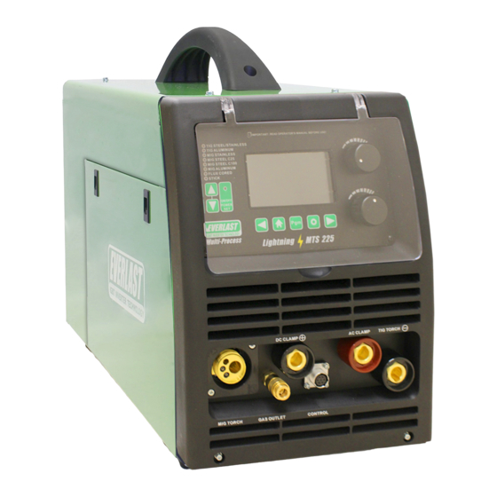
- Page 67 Section 2 Setup Guide FRONT PANEL LIGHTNING MTS 225 CONTROL OUTLET...
- Page 68 Section 2 Setup Guide FRONT PANEL LIGHTNING MTS 225 FRONT PANEL FEATURES AC Connector. The DINSE 35 Style connector is an industry standard sized connector. This terminal has one use only. It is designed to be used only in AC TIG mode. When AC TIG welding mode is selected, the work clamp should be relocated to this terminal.
- Page 69 Section 2 Setup Guide SIDE ACCESS PANEL LIGHTNING MTS 225...
- Page 70 Section 2 Setup Guide SIDE ACCESS PANEL LIGHTNING MTS 225 SIDE PANEL FEATURES 1. Spool Carrier. The spool carrier is designed to carry full-size spools of wire 12” in diameter, and up to 44 lbs. It can also be used with the supplied adapter to carry 8” diameter spools with the supplied adapter.
- Page 71 Section 2 Setup Guide REAR PANEL LIGHTNING MTS 225 1x120/240V...
- Page 72 Water-Cooler Plug. (NA on early models) This is a 240V cooler plug designed for use with Everlast Water Coolers. Do not use this plug for any other application. This is a low amperage outlet and is not designed to power any tools or other acces-...
- Page 73 Section 2 Setup Guide 15 SERIES MIG TORCH NOTICE: Over time, pressure on the drive rolls causes metal fragments from the filler wire’s surface to find its way to the gun cable liner. If the wire guide is not cleaned, it can gradually clog up and causes wire feed malfunctions. If feeding difficulty is observed, clean the liner in the following manner: Remove the welding gun’s gas nozzle, contact tip and contact tip’s adapter.
- Page 74 Section 2 Setup Guide EXPANDED VIEW OF TIG TORCH (Actual appearance may vary slightly from what is listed.) TYPICAL PARTS FOR 26 Series Torch QTY. Long Back Cap with O-Ring Short Back Cap Opt. Torch Head Insulator Collet 1/16 or 3/32 Collet Holder Ceramic Cup #4, 5,6, or 7 Tungsten (customer supplied)
-
Page 75: Mig Operation And Theory
While Everlast uses the term “arc force” on some models as Even though you will find general recommendations about well as inductance on others. The term is the same function setting the Amps, Volts and even shielding gas through a in MIG. - Page 76 Section 3 Setup Guide MIG OPERATION AND THEORY All MIGs have a preset inductance that is inherent in the small amount of extra wire may stick fast in the weld as the machine’s design. However, few MIGs have an adjustable molten puddle begins to cool.
- Page 77 Section 3 Basic Theory and Function MIG OPERATION AND THEORY weld as already mentioned. The gun should have no more arc has melted. than 15 degrees lean pointed into (push) or pointed away from (pull) the direction of travel. In most cases a push Think of weaving as a method of “sewing”...
- Page 78 Section 3 Basic Theory and Function MIG OPERATION AND THEORY welder is capable of handling. A thick pass may also begin to cool before contaminates and gas pockets have the time to float out to the surface. It’s far better to make multiple small- er passes to complete a plate weld for a higher quality result.
- Page 79 Section 3 Basic Theory and Function MIG OPERATION AND THEORY Besides a butt joint and lap joint which are often used for V-GROOVE (60-80°) DOUBLE V-GROOVE thinner metal gauges, consider using one of these groove joints for best welding results. When grinding or cutting the bevels, especially with a single V-groove, it may be beneficial to leave a small land with a gap between the joint to achieve U-GROOVE...
- Page 80 Section 3 Basic Theory and Function MIG OPERATION AND THEORY Problem: Gun is not being held vertical from side to side. Wire is not being directed to the center of the puddle. This concentrates heat on one side of the joint and results in poor fusion on the neglect- ed side.
- Page 81 Section 3 Basic Theory and Function MIG OPERATION AND THEORY Characteristics: Concave weld, poor filling, possible undercutting resulting in weak weld. Possible Causes: Voltage too high, not enough wire speed, too short of wire stick out, wrong gun angle. Remedy: Decrease voltage, use push motion, in- crease wire speed.
- Page 82 Section 3 Basic Theory and Function MIG OPERATION AND THEORY Special Notes Concerning Operation. Welds made with Tri-gas mixes tend to hold 1. Shielding Gas Selection for MIG and TIG. While their rust resistance better. But to reduce the welding aluminum with the Spool gun or MIG heat that is put into the weld , and reduce warp- gun you must use 100% Argon.
- Page 83 When used in MIG mode, you are controlling the from Everlast for your unit. For the best match- Pre-flow, Post-Flow, Start/End WFS, Up and up, we recommend the Parker DSP-360.
-
Page 84: Stick Operation And Theory
Section 3 Basic Theory and Function STICK OPERATION AND THEORY STICK ARC STARTING METHODS Make sure the unit is turned on and the boot cycle has finished. Select the Stick Process on the Selector. Make sure the electrode holder is in the Positive connector and the work clamp is in the negative connector. Select the Amp level desired. -
Page 85: Tig Operation And Theory
Section 3 Basic Theory and Function TIG OPERATION AND THEORY set. Also adjust your Tungsten stick-out to about 1/8” General Setup. The process to set up the welder for and gas flow rate to approximately 16-20 CFH to the basic TIG mode is much less involved than for begin. - Page 86 Section 3 Basic Theory and Function TIG OPERATION AND THEORY cillated in a figure 8 pattern. This will require a fore- hand grip typically, and a good bit of motion of your forearm to accomplish. The filler metal should be moved from side to side to provide an evenly filled puddle under the Tungsten.
- Page 87 Section 3 Basic Theory and Function TIG OPERATION AND THEORY TIG Pulse. The TIG pulse creates two amp values, a EXAMPLE 1 Peak Pulse Amps: 100 amps, high and a low value that cycle back and forth be- Base Amps: 50% tween each other while welding.
- Page 88 Section 3 Basic Theory and Function TIG OPERATION AND THEORY through and speed up welding on thin materials. It but this unique pulse function expands the capabil- can also help maintain a proper bead profile on a ity of the unit on both the maximum and minimum thin edge weld or prevent burn through on extreme- ends of output.
- Page 89 While it is certain The soft square wave may be preferred by older, that others in the industry will follow Everlast’s first more experienced welders, who have spent time on to market model, none will likely be as simple and transformer machine welders.
- Page 90 Section 3 Basic Theory and Function TIG OPERATION AND THEORY increased heating level. Signs of too little cleaning vides penetration in the TIG welding process. Elec- action while welding aluminum are sooty, black or trode positive (EP) creates a strong reverse flow of dull looking welds.
- Page 91 AC balance, it is common to refer to the “amount of cleaning” that is being achieved. Cleaning is a function of Electrode positive and is the reason that the Everlast unit (along with several other brands) refers to AC balance as a percent of full Electrode Positive polarity.
- Page 92 Section 3 Basic Theory and Function TIG ARC STARTING LIFT START OPERATION NOTICE: When using the TIG lift start function, the lift start should be performed using a light touch and a quick, seamless motion. Lift Start is often used anywhere HF use is restricted, particularly in hospitals, or where computers are in close proximity. Steel or Stainless are good candidates for Lift Start operation.
- Page 93 Section 3 Basic Theory and Function TUNGSTEN SELECTION AND SHARPENING TUNGSTEN SHARPENING • Use a dedicated grinding wheel or contamination may result. Do not breath grinding dust! Wear eye protection and gloves. • Grip the Tungsten firmly. • Grind the Tungsten perpendicular to the wheel face. Allow tungsten to grind slowly without much pressure. •...
-
Page 94: Trouble Shooting/Warning Screen Information
When cool, the unit will reset. Allow 5 extra minutes of additional cooling for a safety factor. • Try again. • If unit will not clear the warning after 15 minutes, turn off and back on. • If unit does not clear after cycling the power switch contact Everlast. •... - Page 95 Internal fault has been caused by an external condition • IGBT or PC board failure. • What to do: Turn off unit immediately. • Investigate cause, remedy if possible. • Try again. • If cause cannot be found call Everlast. •...
- Page 96 Investigate cause, remedy if possible. Check work clamp connection, proper function of switch, Gas • flow/type, polarity, foot pedal and torch switch operation. Try again. • If cause cannot be found reset unit by cycling power switch. • If warning does not clear, call Everlast. •...
- Page 97 Wire continues feeding but no arc is wires. Check power plug for problems. If easily tripped the present. Resistor value too low. (Contact Everlast if OC is tripping regularly with normal settings.) Potentiometer damaged. Repair or Replace it.
- Page 98 Solenoid is sticking. Too flow of gas. Listen for audible click of gas solenoid. If no short of pre-flow or post-flow click is heard, then contact Everlast Support. Clean weld properly. Increase pre flow or post flow. Unstable Arc.
Need help?
Do you have a question about the Lightning MTS 225 and is the answer not in the manual?
Questions and answers