Grundfos ALPHA2 L Manual
- Installation and operating instructions manual (41 pages) ,
- Instructions manual (31 pages) ,
- Manual (19 pages)
Advertisement
- 1 Symbols used in this document
- 2 General description
- 3 Applications
- 4 Installation
- 5 Electrical connection
- 6 Control panel
- 7 Setting the pump
- 8 Systems with bypass valve between flow and return pipes
- 9 Start-up
- 10 Pump settings and pump performance
- 11 Fault finding chart
- 12 Technical data and installation dimensions
- 13 Performance curves
- 14 Features
- 15 Accessories
- 16 Documents / Resources
Symbols used in this document

If these safety instructions are not observed, it may result in personal injury!

If these safety instructions are not observed, it may result in malfunction or damage to the equipment!
Note
Notes or instructions that make the job easier and ensure safe operation.
General description
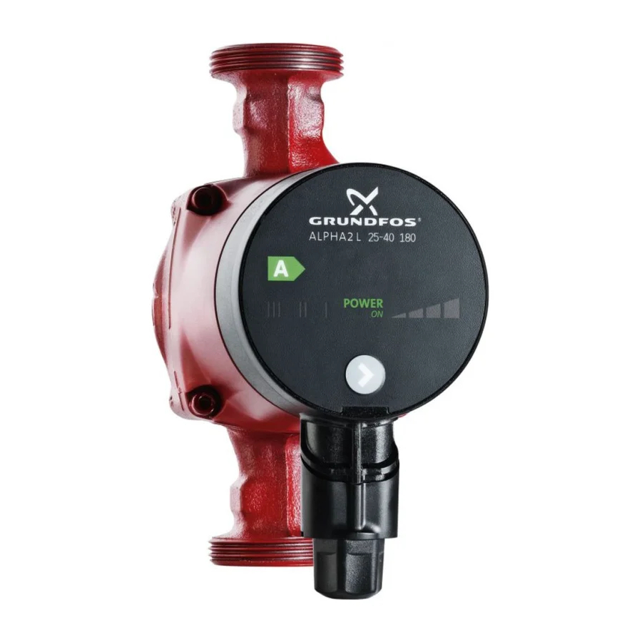
The GRUNDFOS ALPHA2 L circulator pump
The GRUNDFOS ALPHA2 L circulator pump is designed for the circulation of water in heating systems.
Install the GRUNDFOS ALPHA2 L in
- underfloor heating systems
- one-pipe systems
- two-pipe systems.
GRUNDFOS ALPHA2 L incorporates a permanent-magnet motor and differential-pressure control enabling continuous adjustment of the pump performance to the actual system requirements.
GRUNDFOS ALPHA2 L has a user-friendly front-mounted control panel. See Control panel and Features.
Advantages of installing a GRUNDFOS ALPHA2 L
The installation of a GRUNDFOS ALPHA2 L means
easy installation and start-up
- GRUNDFOS ALPHA2 L is easy to install.
With the factory setting, the pump can, in most cases, be started without making any settings.
high degree of comfort
- Minimum noise from valves, etc.
low energy consumption
- Low energy consumption compared to conventional circulator pumps. The GRUNDFOS ALPHA2 L is A-labelled.
![]()

Applications
System types
GRUNDFOS ALPHA2 L is suitable for
- systems with constant or variable flows where it is desirable to optimise the setting of the pump duty point
- systems with variable flow-pipe temperature.
Pumped liquids
Clean, thin, non-aggressive and non-explosive liquids, not containing solid particles, fibres or mineral oil.

In heating systems, the water should meet the requirements of accepted standards on water quality in heating systems, e.g. the German standard VDI 2035.
The pump must not be used for the transfer of flammable liquids such as diesel oil, petrol and similar liquids.
System pressure
Maximum 1.0 MPa (10 bar). See fig. 2.
Relative air humidity (RH)
Maximum 95%. See fig. 2.
Enclosure class
IP 42. See fig. 2.
Inlet pressure
Minimum inlet pressure in relation to liquid temperature. See fig. 2.
| Liquid temperature | Minimum inlet pressure | |
| [MPa] | [bar] | |
| ≤ 75°C | 0.005 | 0.05 |
| 90°C | 0.028 | 0.28 |
| 110°C | 0.108 | 1.08 |
Installation
Mounting
Arrows on the pump housing indicate the liquid flow direction through the pump.
See Installation dimensions – GRUNDFOS ALPHA2 L XX-40, XX-50, XX-60.

- Fit the two gaskets supplied when the pump is mounted in the pipe. See fig. 3, pos. A.
- Install the pump with the motor shaft horizontal. See fig. 3, pos. B.
Control box positions
The pumped liquid may be scalding hot and under high pressure!
Drain the system or close the isolating valves on either side of the pump before the screws are removed.
When the position of the control box has been changed, fill the system with the liquid to be pumped or open the isolating valves.

Changing the control box position
The control box can be rotated in steps of 90 °.
Possible/permissible positions and the procedure of changing the position of the control box are illustrated in fig. 4, pos. A.
Procedure:
- Slacken and remove the four hexagon-socket head screws holding the pump head with a tee key (M4).
- Turn the pump head to the desired position.
- Insert and cross-tighten the screws.
Insulation of pump housing
Note
Limit the heat loss from the pump housing and pipework.
The heat loss from the pump and pipework can be reduced by insulating the pump housing and the pipe.

As an alternative, polystyrene insulation shells can be ordered from Grundfos. See Accessories.
Do not insulate the control box or cover the control panel.
Electrical connection
The electrical connections and protection must be carried out in accordance with local regulations.

The pump must be connected to earth ![]() .
.
The pump must be connected to an external mains switch with a minimum contact gap of 3 mm in all poles.
- The motor requires no external motor protection.
- Check that the supply voltage and frequency correspond to the values stated on the pump. See Nameplate.
- Connect the pump to the mains with the plug supplied with the pump as shown in fig. 6, steps 1 to 8.
- Light in the control panel shows that the electricity supply has been switched on.
Control panel
Elements on the control panel

The control panel on the GRUNDFOS ALPHA2 L comprises:
| Pos. | Description |
| 1 | "POWER ON" indicator light |
| 2 | Seven light fields indicating the pump setting |
| 3 | Push-button for selection of pump setting |
"POWER ON" indicator light
The "POWER ON" indicator light, see fig. 7, pos. 1, is on when the electricity has been switched on.
When the "POWER ON" indicator light is on only, a fault preventing the pump from operating properly (e.g. seizing-up) has occurred.
If a fault is indicated, correct the fault and reset the pump by switching the electricity supply off and on.
Light fields indicating the pump setting
GRUNDFOS ALPHA2 L has seven optional settings which can be selected with the push-button. See fig. 7, pos. 3.
The pump setting is indicated by seven different light fields.

| Button presses | Light field | Description |
| 0 | PP2 (factory setting) | Highest proportional-pressure curve |
| 1 | CP1 | Lowest constant-pressure curve |
| 2 | CP2 | Highest constant-pressure curve |
| 3 | III | Constant curve, speed III |
| 4 | II | Constant curve, speed II |
| 5 | I | Constant curve, speed I |
| 6 | PP1 | Lowest proportional-pressure curve |
| 7 | PP2 | Highest proportional-pressure curve |
See Pump settings and pump performance for information about the function of the settings.
Push-button for selection of pump setting
Every time the push-button is pressed, see fig. 7, pos. 3, the pump setting is changed.
A cycle is seven button presses. See Light fields indicating the pump setting.
Setting the pump
Pump setting for system type
Factory setting = Highest proportional-pressure curve (PP2).
Recommended and alternative pump settings according to fig. 9:

| Pos. | System type | Pump setting | |
| Recommended | Alternative | ||
| A | Underfloor heating | Lowest constant-pressure curve (CP1)* | Highest constant-pressure curve (CP2)* |
| B | Two-pipe systems | Highest proportional-pressure curve (PP2)* | Lowest proportional-pressure curve (PP1)* |
| C | One-pipe systems | Lowest proportional-pressure curve (PP1)* | Highest proportional-pressure curve (PP2)* |
* See Guide to performance curves.
Changing from recommended to alternative pump setting
Heating systems are "slow" systems that cannot be set to the optimum operation within minutes or hours.
If the recommended pump setting does not give the desired distribution of heat in the rooms of the house, change the pump setting to the shown alternative.
Explanation to pump settings in relation to performance curves, see Pump settings and pump performance.
Pump control
During operation, the pump head will be controlled according to the principle "proportional-pressure control" (PP) or "constant-pressure control" (CP).
In these control modes, the pump performance and consequently the power consumption are adjusted according to the heat demand in the system.
Proportional-pressure control
In this control mode, the differential pressure across the pump is controlled according to the flow.
The proportional-pressure curves are indicated by PP1 and PP2 in the Q/H diagrams. See Pump settings and pump performance.
Constant-pressure control
In this control mode, a constant differential pressure across the pump is maintained, irrespective of the flow.
The constant-pressure curves are indicated by CP1 and CP2 and are the horizontal performance curves in the Q/H diagrams. See Pump settings and pump performance.
Systems with bypass valve between flow and return pipes
Purpose of bypass valve
Bypass valve
The purpose of the bypass valve is to ensure that the heat from the boiler can be distributed when all valves in the underfloor-heating circuits and/or thermostatic radiator valves are closed.

System elements:
- bypass valve
- flowmeter, pos. A.
The minimum flow must be present when all valves are closed.
The pump setting depends on the type of bypass valve used, i.e. manually operated or thermostatically controlled.
Manually operated bypass valve
Follow this procedure:
- Adjust the bypass valve with the pump in setting I (speed I).
The minimum flow (Qmin.) for the system must always be observed. Consult the manufacturer's instructions. - When the bypass valve has been adjusted, set the pump according to Setting the pump.
Automatic bypass valve (thermostatically controlled)
Follow this procedure:
- Adjust the bypass valve with the pump in setting I (speed I).
The minimum flow (Qmin.) for the system must always be observed. Consult the manufacturer's instructions. - When the bypass valve has been adjusted, set the pump to the lowest or highest constant-pressure curve.
Explanation to pump settings in relation to performance curves, see Pump settings and pump performance.
Start-up
Before start-up
Do not start the pump until the system has been filled with liquid and vented. The required minimum inlet pressure must be available at the pump inlet. See Applications and Technical data and installation dimensions.
Venting the pump
The pump is self-venting. It need not be vented before start-up.
Air in the pump may cause noise. This noise ceases after a few minutes running.
Quick venting of the pump can be obtained by setting the pump to speed III for a short period, depending on system size and design.
When the pump has been vented, i.e. when the noise has ceased, set the pump according to the recommendations. See Setting the pump.

The pump must not run dry.
The system cannot be vented through the pump. See Venting of heating systems.
Venting of heating systems
The heating system can be vented via an air escape valve installed above the pump (1).
In heating systems that often contain much air, Grundfos recommends the installation of pumps with pump housing with air separator, i.e. ALPHA2 pumps, type ALPHA2 XX-XX A.

When the heating system has been filled with liquid, follow this procedure:
- Open the air escape valve.
- Set the pump to speed III.
- Let the pump run for a short period, depending on system size and design.
- When the system has been vented, i.e. when the possible noise has ceased, set the pump according to the recommendations. See Setting the pump.
Repeat the procedure, if necessary.
The pump must not run dry.
Pump settings and pump performance
Relation between pump setting and pump performance
Figure 13 shows the relation between pump setting and pump performance by means of curves. See also Performance curves.

| Setting | Pump curve | Function |
| PP1 | Lowest proportional pressure curve | The duty point of the pump will move up or down on the lowest proportional-pressure curve, see fig. 13, depending on the heating demand. The head (pressure) is reduced at falling heating demand and increased at rising heating demand. |
| PP2 (factory setting) | Highest proportional pressure curve | The duty point of the pump will move up or down on the highest proportional-pressure curve, see fig. 13, depending on the heating demand. The head (pressure) is reduced at falling heating demand and increased at rising heating demand. |
| CP1 | Lowest constant pressure curve | The duty point of the pump will move out or in on the lowest constant-pressure curve, see fig. 13, depending on the heating demand in the system. The head (pressure) is kept constant, irrespective of the heating demand. |
| CP2 | Highest constant pressure curve | The duty point of the pump will move out or in on the highest constant-pressure curve, see fig. 13, depending on the heating demand in the system. The head (pressure) is kept constant, irrespective of the heating demand. |
| III | Speed III | ALPHA2 L runs at a constant speed and consequently on a constant curve. In speed III, the pump is set to run on the max. curve under all operating conditions. See fig. 13. Quick venting of the pump can be obtained by setting the pump to speed III for a short period. See Venting the pump. |
| II | Speed II | ALPHA2 L runs at a constant speed and consequently on a constant curve. In speed II, the pump is set to run on the medium curve under all operating conditions. See fig. 13. |
| I | Speed I | ALPHA2 L runs at a constant speed and consequently on a constant curve. In speed I, the pump is set to run on the min. curve under all operating conditions. See fig. 13. |
Fault finding chart
Before starting any work on the pump, make sure that the electricity supply has been switched off and that it cannot be accidentally switched on.
| Fault | Control panel | Cause | Remedy |
| Light off. |
| Replace the fuse. |
| Cut in the circuit breaker. | ||
| Replace the pump. | ||
| "POWER ON" is on only. |
| Check that the electricity supply falls within the specified range. | |
| Remove the impurities. | ||
| "POWER "ON" and the light field for pump setting are on. |
| Vent the system. See Venting of heating systems. |
| Reduce the suction head. See Pump settings and pump performance. | ||
| "POWER "ON" and the light field for pump setting are on. |
| Let the pump run. It vents itself over time. See Venting the pump. |
| Increase the inlet pressure or check the air volume in the expansion tank, if installed. | ||
| "POWER "ON" and the light field for pump setting are on. |
| Increase the suction head. See Pump settings and pump performance. |
Technical data and installation dimensions
Technical data
| Supply voltage | 1 x 230 V – 10%/+ 6%, 50 Hz, PE | ||||||||||||||||||||||||
| Motor protection | The pump requires no external motor protection. | ||||||||||||||||||||||||
| Enclosure class | IP 42 | ||||||||||||||||||||||||
| Insulation class | F | ||||||||||||||||||||||||
| Relative air humidity | Maximum 95% | ||||||||||||||||||||||||
| System pressure | Maximum 1.0 MPa, 10 bar, 102 m head | ||||||||||||||||||||||||
| Inlet pressure | Liquid temperature | Minimum inlet pressure | |||||||||||||||||||||||
| ≤ +75°C | 0.05 bar, 0.005 MPa, 0.5 m head | ||||||||||||||||||||||||
| +90°C | 0.28 bar, 0.028 MPa, 2.8 m head | ||||||||||||||||||||||||
| +110°C | 1.08 bar, 0.108 MPa, 10.8 m head | ||||||||||||||||||||||||
| EMC | EN 61000-6-2 and EN 61000-6-3 | ||||||||||||||||||||||||
| Sound pressure level | The sound pressure level of the pump is lower than 43 dB(A). | ||||||||||||||||||||||||
| Ambient temperature | 0°C to +40°C | ||||||||||||||||||||||||
| Temperature class | TF110 to CEN 335-2-51 | ||||||||||||||||||||||||
| Surface temperature | The maximum surface temperature will not exceed +125°C. | ||||||||||||||||||||||||
| Liquid temperature | +2°C to +110°C | ||||||||||||||||||||||||
To avoid condensation in the control box and stator, the liquid temperature must always be higher than the ambient temperature.
| |||||||||||||||||||||||||
Installation dimensions
GRUNDFOS ALPHA2 L XX-40, XX-50, XX-60

| Pump type | Dimensions | ||||||||
| L1 | B1 | B2 | B3 | B4 | H1 | H2 | H3 | G | |
| ALPHA2 L 15-40 130 | 130 | 77 | 78 | 46 | 49 | 27 | 129 | 79 | 1 |
| ALPHA2 L 15-50 130* | 130 | 77 | 78 | 46 | 49 | 27 | 129 | 79 | 1 1/2 |
| ALPHA2 L 25-40 130 | 130 | 77 | 78 | 46 | 49 | 27 | 129 | 79 | 1 1/2 |
| ALPHA2 L 25-40 180 | 180 | 78 | 77 | 47 | 48 | 26 | 127 | 81 | 1 1/2 |
| ALPHA2 L 32-40 180 | 180 | 78 | 77 | 47 | 48 | 26 | 127 | 81 | 2 |
| ALPHA2 L 15-60 130 | 130 | 77 | 78 | 46 | 49 | 27 | 129 | 79 | 1** |
| ALPHA2 L 25-60 130 | 130 | 77 | 78 | 46 | 49 | 27 | 129 | 79 | 1 1/2 |
| ALPHA2 L 25-60 180 | 180 | 78 | 77 | 47 | 48 | 26 | 127 | 81 | 1 1/2 |
| ALPHA2 L 32-60 180 | 180 | 78 | 77 | 47 | 48 | 26 | 127 | 81 | 2 |
*) For the UK market only.
**) For UK 1 1/2.
Performance curves
Guide to performance curves
Each pump setting has its own performance curve (Q/H curve).
A power curve (P1 curve) belongs to each Q/H curve. The power curve shows the pump power consumption (P1) in Watt at a given Q/H curve.
The P1 value corresponds to the value that can be read from the pump display:

| Setting | Pump curve |
| PP1 | Lowest proportional-pressure curve |
| PP2 (factory setting) | Highest proportional-pressure curve |
| CP1 | Lowest constant-pressure curve |
| CP2 | Highest constant-pressure curve |
| III | Constant speed, speed III |
| II | Constant speed, speed II |
| I | Constant speed, speed I |
For further information about pump settings, see
Light fields indicating the pump setting
Setting the pump
Pump settings and pump performance.
Curve conditions
The guidelines below apply to the curves on the next pages:
- Test liquid: Airless water.
- The curves apply to a density of ρ = 983.2 kg/m3 and a liquid temperature of +60°C.
- All curves show average values and should not be used as guarantee curves. If a specific minimum performance is required, individual measurements must be made.
- The curves for speeds I, II and III are marked.
- The curves apply to a kinematic viscosity of υ = 0.474 mm2/s (0.474 cSt).
Performance curves, ALPHA2 L XX-40

Performance curves, ALPHA2 L XX-50

Performance curves, ALPHA2 L XX-60

Features
Nameplate

| Pos. | Description |
| 1 | Pump type |
| 2 | Product number |
| 3 | Serial number |
| 4 | Production code
|
| 5 | Enclosure class |
| 6 | Voltage [V] |
| 7 | Frequency [Hz] |
| 8 | Rated current [A]:
|
| 9 | Input power P1 [W]:
|
| 10 | Maximum system pressure [MPa] |
| 11 | CE mark and approvals |
| 12 | Country of origin |
| 13 | Temperature class |
Type key

Accessories
Accessories for GRUNDFOS ALPHA2 L.

Accessories include
- fittings (unions and valves)
- insulation kits (insulation shells)
- plug.
Argentina
Bombas GRUNDFOS de Argentina S.A.
Ruta Panamericana km. 37.500 Lote
34A
1619 - Garin
Pcia. de Buenos Aires
Phone: +54-3327 414 444
Telefax: +54-3327 411 111
Australia
GRUNDFOS Pumps Pty. Ltd.
P.O. Box 2040
Regency Park
South Australia 5942
Phone: +61-8-8461-4611
Telefax: +61-8-8340 0155
Austria
GRUNDFOS Pumpen Vertrieb
Ges.m.b. H.
Grundfosstraße 2
A-5082 Grödig/Salzburg
Tel.: +43-6246-883-0
Telefax: +43-6246-883-30
Belgium
N.V. GRUNDFOS Bellux S.A.
Boomsesteenweg 81-83
B-2630 Aartselaar
Tél.: +32-3-870 7300
Télécopie: +32-3-870 7301
Belorussia
Представительство ГРУНДФОС в Минске
220090 Минск ул.Олешева 14
Телефон: (8632) 62-40-49
Факс: (8632) 62-40-49
Bosnia/Herzegovina
GRUNDFOS Sarajevo
Paromlinska br. 16,
BiH-71000 Sarajevo
Phone: +387 33 713290
Telefax: +387 33 231795
Brazil
Mark GRUNDFOS Ltda.
Av. Humberto de Alencar Castelo
Branco, 630
CEP 09850 - 300
São Bernardo do Campo - SP
Phone: +55-11 4393 5533
Telefax: +55-11 4343 5015
Bulgaria
GRUNDFOS Pumpen Vertrieb
Representative Office - Bulgaria
Bulgaria, 1421 Sofia
Lozenetz District
105-107 Arsenalski blvd.
Phone: +359 2963 3820, 2963 5653
Telefax: +359 2963 1305
Canada
GRUNDFOS Canada Inc.
2941 Brighton Road
Oakville, Ontario
L6H 6C9
Phone: +1-905 829 9533
Telefax: +1-905 829 9512
China
GRUNDFOS Pumps (Shanghai) Co. Ltd.
51 Floor, Raffles City
No. 268 Xi Zang Road. (M)
Shanghai 200001
PRC
Phone: +86-021-612 252 22
Telefax: +86-021-612 253 33
Croatia
GRUNDFOS predstavništvo Zagreb
Cebini 37, Buzin
HR-10000 Zagreb
Phone: +385 1 6595 400
Telefax: +385 1 6595 499
Czech Republic
GRUNDFOS s.r.o.
Čajkovského 21
779 00 Olomouc
Phone: +420-585-716 111
Telefax: +420-585-716 299
Denmark
GRUNDFOS DK A/S
Martin Bachs Vej 3
DK-8850 Bjerringbro
Tlf.: +45-87 50 50 50
Telefax: +45-87 50 51 51
E-mail: info_GDK@grundfos.com
www.grundfos.com/DK
Estonia
GRUNDFOS Pumps Eesti OÜ
Peterburi tee 92G
11415 Tallinn
Tel: + 372 606 1690
Fax: + 372 606 1691
Finland
OY GRUNDFOS Pumput AB
Mestarintie 11
FIN-01730 Vantaa
Phone: +358-3066 5650
Telefax: +358-3066 56550
France
Pompes GRUNDFOS Distribution S.A.
Parc d'Activités de Chesnes
57, rue de Malacombe
F-38290 St. Quentin Fallavier (Lyon)
Tél.: +33-4 74 82 15 15
Télécopie: +33-4 74 94 10 51
Germany
GRUNDFOS GMBH
Schlüterstr. 33
40699 Erkrath
Tel.: +49-(0) 211 929 69-0
Telefax: +49-(0) 211 929 69-3799
e-mail: infoservice@grundfos.de
Service in Deutschland:
e-mail: kundendienst@grundfos.de
Greece
GRUNDFOS Hellas A.E.B.E.
20th km. Athinon-Markopoulou Av.
P.O. Box 71
GR-19002 Peania
Phone: +0030-210-66 83 400
Telefax: +0030-210-66 46 273
Hong Kong
GRUNDFOS Pumps (Hong Kong) Ltd.
Unit 1, Ground floor
Siu Wai Industrial Centre
29-33 Wing Hong Street &
68 King Lam Street, Cheung Sha Wan
Kowloon
Phone: +852-27861706 / 27861741
Telefax: +852-27858664
Hungary
GRUNDFOS Hungária Kft.
Park u. 8
H-2045 Törökbálint,
Phone: +36-23 511 110
Telefax: +36-23 511 111
India
GRUNDFOS Pumps India Private Limited
118 Old Mahabalipuram Road
Thoraipakkam
Chennai 600 096
Phone: +91-44 2496 6800
Indonesia
PT GRUNDFOS Pompa
Jl. Rawa Sumur III, Blok III / CC-1
Kawasan Industri, Pulogadung
Jakarta 13930
Phone: +62-21-460 6909
Telefax: +62-21-460 6910 / 460 6901
Ireland
GRUNDFOS (Ireland) Ltd.
Unit A, Merrywell Business Park
Ballymount Road Lower
Dublin 12
Phone: +353-1-4089 800
Telefax: +353-1-4089 830
Italy
GRUNDFOS Pompe Italia S.r.l.
Via Gran Sasso 4
I-20060 Truccazzano (Milano)
Tel.: +39-02-95838112
Telefax: +39-02-95309290 / 95838461
Japan
GRUNDFOS Pumps K.K.
Gotanda Metalion Bldg., 5F,
5-21-15, Higashi-gotanda
Shiagawa-ku, Tokyo
141-0022 Japan
Phone: +81 35 448 1391
Telefax: +81 35 448 9619
Korea
GRUNDFOS Pumps Korea Ltd.
6th Floor, Aju Building 679-5
Yeoksam-dong, Kangnam-ku, 135-916
Seoul, Korea
Phone: +82-2-5317 600
Telefax: +82-2-5633 725
Latvia
SIA GRUNDFOS Pumps Latvia
Deglava biznesa centrs
Augusta Deglava ielā 60, LV-1035, Rīga,
Tālr.: + 371 714 9640, 7 149 641
Fakss: + 371 914 9646
Lithuania
GRUNDFOS Pumps UAB
Smolensko g. 6
LT-03201 Vilnius
Tel: + 370 52 395 430
Fax: + 370 52 395 431
Malaysia
GRUNDFOS Pumps Sdn. Bhd.
7 Jalan Peguam U1/25
Glenmarie Industrial Park
40150 Shah Alam Selangor
Phone: +60-3-5569 2922
Telefax: +60-3-5569 2866
México
Bombas GRUNDFOS de México S.A. de C.V.
Boulevard TLC No. 15
Parque Industrial Stiva Aeropuerto
Apodaca, N.L. 66600
Phone: +52-81-8144 4000
Telefax: +52-81-8144 4010
Netherlands
GRUNDFOS Netherlands
Veluwezoom 35
1326 AE Almere
Postbus 22015
1302 CA ALMERE
Tel.: +31-88-478 6336
Telefax: +31-88-478 6332
e-mail: info_gnl@grundfos.com
New Zealand
GRUNDFOS Pumps NZ Ltd.
17 Beatrice Tinsley Crescent
North Harbour Industrial Estate
Albany, Auckland
Phone: +64-9-415 3240
Telefax: +64-9-415 3250
Norway
GRUNDFOS Pumper A/S
Strømsveien 344
Postboks 235, Leirdal
N-1011 Oslo
Tlf.: +47-22 90 47 00
Telefax: +47-22 32 21 50
Poland
GRUNDFOS Pompy Sp. z o.o.
ul. Klonowa 23
Baranowo k. Poznania
PL-62-081 Przeźmierowo
Tel: (+48-61) 650 13 00
Fax: (+48-61) 650 13 50
Portugal
Bombas GRUNDFOS Portugal, S.A.
Rua Calvet de Magalhães, 241
Apartado 1079
P-2770-153 Paço de Arcos
Tel.: +351-21-440 76 00
Telefax: +351-21-440 76 90
România
GRUNDFOS Pompe România SRL
Bd. Biruintei, nr 103
Pantelimon county Ilfov
Phone: +40 21 200 4100
Telefax: +40 21 200 4101
E-mail: romania@grundfos.ro
Russia
ООО Грундфос
Россия, 109544 Москва, ул. Школьная 39
Тел. (+7) 495 737 30 00, 564 88 00
Факс (+7) 495 737 75 36, 564 88 11
E-mail grundfos.moscow@grundfos.com
Serbia
GRUNDFOS Predstavništvo Beograd
Dr. Milutina Ivkovića 2a/29
YU-11000 Beograd
Phone: +381 11 26 47 877 / 11 26 47 496
Telefax: +381 11 26 48 340
Singapore
GRUNDFOS (Singapore) Pte. Ltd.
24 Tuas West Road
Jurong Town
Singapore 638381
Phone: +65-6865 1222
Telefax: +65-6861 8402
Slovenia
GRUNDFOS PUMPEN VERTRIEB
Ges.m.b. H.,
Podružnica Ljubljana
Blatnica 1, SI-1236 Trzin
Phone: +386 01 568 0610
Telefax: +386 01 568 0619
E-mail: slovenia@grundfos.si
Spain
Bombas GRUNDFOS España S.A.
Camino de la Fuentecilla, s/n
E-28110 Algete (Madrid)
Tel.: +34-91-848 8800
Telefax: +34-91-628 0465
Sweden
GRUNDFOS AB
Box 333 (Lunnagårdsgatan 6)
431 24 Mölndal
Tel.: +46(0)771-32 23 00
Telefax: +46(0)31-331 94 60
Switzerland
GRUNDFOS Pumpen AG
Bruggacherstrasse 10
CH-8117 Fällanden/ZH
Tel.: +41-1-806 8111
Telefax: +41-1-806 8115
Taiwan
GRUNDFOS Pumps (Taiwan) Ltd.
7 Floor, 219 Min-Chuan Road
Taichung, Taiwan, R.O.C.
Phone: +886-4-2305 0868
Telefax: +886-4-2305 0878
Thailand
GRUNDFOS (Thailand) Ltd.
92 Chaloem Phrakiat Rama 9 Road,
Dokmai, Pravej, Bangkok 10250
Phone: +66-2-725 8999
Telefax: +66-2-725 8998
Turkey
GRUNDFOS POMPA San. ve Tic. Ltd. Sti.
Gebze Organize Sanayi Bölgesi
Ihsan dede Caddesi,
2. yol 200. Sokak No. 204
41490 Gebze/ Kocaeli
Phone: +90 - 262-679 7979
Telefax: +90 - 262-679 7905
E-mail: satis@grundfos.com
Ukraine
ТОВ ГРУНДФОС УКРАЇНА
01010 Київ, Вул. Московська 8б,
Тел.:(+38 044) 390 40 50
Фах.: (+38 044) 390 40 59
E-mail: ukraine@grundfos.com
United Arab Emirates
GRUNDFOS Gulf Distribution
P.O. Box 16768
Jebel Ali Free Zone
Dubai
Phone: +971-4- 8815 166
Telefax: +971-4-8815 136
United Kingdom
GRUNDFOS Pumps Ltd.
Grovebury Road
Leighton Buzzard/Beds. LU7 8TL
Phone: +44-1525-850000
Telefax: +44-1525-850011
U.S.A.
GRUNDFOS Pumps Corporation
17100 West 118th Terrace
Olathe, Kansas 66061
Phone: +1-913-227-3400
Telefax: +1-913-227-3500
Usbekistan
Представительство ГРУНДФОС в Ташкенте
700000 Ташкент ул.Усмана Носира 1-й тупик 5
Телефон: (3712) 55-68-15
Факс: (3712) 53-36-35
www.grundfos.com
Documents / ResourcesDownload manual
Here you can download full pdf version of manual, it may contain additional safety instructions, warranty information, FCC rules, etc.
Advertisement


Need help?
Do you have a question about the ALPHA2 L and is the answer not in the manual?
Questions and answers