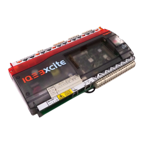
Advertisement
Quick Links
Important: Retain these instructions
CONTENTS
1
Installation - Mounting ....................................................... 1
1 Installation - Mounting
1
Install
Install according to IQ3xact or
IQ3xcite installation instructions
section 3 steps 1 to 11
IQ3xact Installation Instructions TG200766
IQ3xcite Installation Instructions TG200626
either RS485 2 wire, RS485 4 wire, or RS422
2 part connector with 5 screw terminals fo 0.5 to 2.5 mm
section area (14 to 20 AWG) cable
If RS485 2 wire
32 devices maximum
A B
0V
IQ3../.../SER/XNC/...
RB
RA
B
T
A
T
0V
Terminator switch ON
If RS485 4 wire
32 devices maximum
0V TA TB RA RB
IQ3../.../SER/XNC/...
RB
RA
B
T
A
T
0V
Terminator switch ON
IQ3../.../XNC/... Controller/Interface Installation Instructions TG200911 Issue 1/D 03/09/07
1
1
2
2
3
3
4
4
5
5
6
6
7
7
8
8
9
9
10 11 12
13 14 15
16 17 18
19 20 21
1
2
3
4
5
6
7
+
+
0
0
+
0
+
0
+
0
+
0
+
0
+
0
TX
RX
RTS/TXEN
CTS/RXEN
RS485
RS232
100-240 V
A
11
P
0 P
OK
RX
P
31 32 33
cross
2
A B
A B
0V
0V
120 ohm
terminator
0V TA TB RA RB
0V TA TB RA RB
120 ohm
terminators
Installation Instructions
IQ3.../.../XNC/...
Controller/Interface
2
Installation - Configuration ................................................ 4
3
Insertion/Replacement of battery ..................................... 7
4
Disposal ............................................................................. 8
2
Connect Serial Interface
If /SER/.., serial interface auxiliary board, fitted
Note that only one of the RS232 or RS485 connectors can have
a cable connected at any one time in order to comply with Class
B EMC emission standard (EN61000-6-3, residential, commercial,
and light industrial environments).
WARNING: Failure to comply with this requirement will reduce
the unit to Class A (industrial environments); in a domestic
environment the unit may cause radio interference, in which
case the user may be required to take adequate measures.
22 23 24
25 26 27
28 29 30
8
9
10
+
0
+
0
+
0
12
13
14
15
16
0
P
0
P
0
P
0
P
0
34 35 36
37 38 39
40 41 42
43 44 45
46 47 48
or RS232
either 9 way D type plug
1
6
2
RX
Note pins 1,6,9 - no connection
RTS
7
3
TX
CTS
8
4
(held high)
9
5
GND
or RJ11 socket
RX
1
2
Note pin 2 - no connection
3
CTS
4
RTS
5
GND
TX
6
Note that only one of the two RS232 connectors can be used at a time
If RS422
external 100 ohm
IQ3../.../SER/XNC/...
terminator
RB
RA
B
T
A
T
0V
Terminator switch OFF
If the IQ3/XNC/SER controller and its slave units are in the same
cabinet using the same power supply, each device should have
a good physical earth (ground) connection.
0V
TA
TB
RA
RB
100 ohm
terminator
Step 2 continued over page
1
Advertisement

Subscribe to Our Youtube Channel
Summary of Contents for TREND IQ3 series
- Page 1 Installation Instructions IQ3.../.../XNC/... Controller/Interface Important: Retain these instructions CONTENTS Installation - Configuration ..........4 Insertion/Replacement of battery ........7 Installation - Mounting ............1 Disposal ................8 1 Installation - Mounting Install Connect Serial Interface Install according to IQ3xact or If /SER/.., serial interface auxiliary board, fitted IQ3xcite installation instructions section 3 steps 1 to 11...
- Page 2 IQ3../.../XNC/... Installation Instructions 1 Installation - Mounting (continued) Connect Serial Interface (continued) RS485 2 wire, RS485 4 wire, or RS422 (continued) If the IQ3/XNC/SER controller and its slave units are in different cabinets or use different power supplies (e.g. different UPSs), the cabinets should be isolated from each other.
- Page 3 Installation Instructions IQ3../.../XNC/... 1 Installation - Mounting (continued) Connect IQ System Current Loop Network If /LAN/.., IQ system current loop Lan auxiliary board, fitted Network Engineering Manual, 92-1735 2 off 2 part connectors with 4 screw terminals for 0.5 to 2.5 mm cross section area (14 to 20 AWG) cable polarity independent...
- Page 4 IQ3../.../XNC/... Installation Instructions 2 Installation - Configuration Continue Installation Complete IQ3../.../XNC/... installation instructions sheet 1 and IQ3xact installation instructions up to section 4 step 19, IQ3../.../XNC/... Installation Instructions TG200911 sheet 1 or IQ3xcite Installation Instructions up to section 4 step 20. IQ3xact Installation Instructions TG200766 IQ3xcite Installation Instructions TG200626 Select Terminator Switch Position...
- Page 5 Installation Instructions IQ3../.../XNC/... 2 Installation - Configuration (continued) Check current loop network If /LAN/.., IQ system current loop Lan auxiliary board, fitted 10 11 12 13 14 15 16 17 18 19 20 21 22 23 24 25 26 27 28 29 30 IQ3../.../LAN/XNC/...
- Page 6 IQ3../.../XNC/... Installation Instructions 2 Installation - Configuration (continued) Download TCL Application TCLTool2 ManualTC200832 Use TCLTool2 or SET to download TCL Application (XNC file) SET Manual TE200147 Note that if XNC (TCL application) file is protected, the installer should send MAC address(es) of the targetted controller(s) to the XNC file supplier.
- Page 7 Installation Instructions IQ3../.../XNC/... 3 Insertion/Replacement of Battery (if battery required) Isolate I/O Switch Off 10 11 12 13 14 15 16 17 18 WARNING: The connecting leads may be connected to supplies. Isolate before touching. 100-240 V 31 32 33 34 35 36 37 38 39 40 41 42...
- Page 8 Bois 37,Switzerland by its Authorized Representative, Trend Control Systems Limited. Trend Control Systems Limited reserves the right to revise this publication from time to time and make changes to the content hereof without obligation to notify any person of such revisions or changes.


Need help?
Do you have a question about the IQ3 series and is the answer not in the manual?
Questions and answers