Advertisement
Quick Links
Installation Instructions - Sheet 1
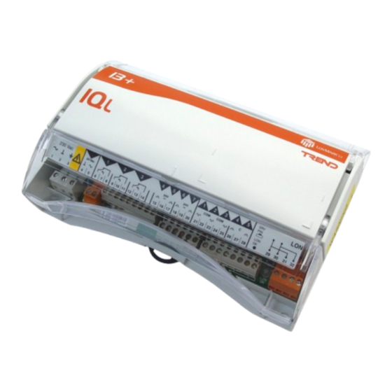
IQL13+/xxx
LonMark Terminal Unit Controllers
Important: Retain these instructions
CONTENTS
1.1 Unpacking
1.2 Storage
SHEET 1: Installation Instructions - Sheet 1
1.1 Unpacking
1.2 Storage
-10 °C
+50 °C
(14 °F)
(122 °F)
1.3 Installation - Fixing
1
Dimensions
205 mm (8.07")
1 3 +
L
1
2
3
4
2 3 0 V a c
2 4 V a c
2 4 V
~
1
2
3
4
5
6
7
8
9
1 0
1 1
1 2
1 3
1 4
1 5
1 6
75 mm (3")
IQL13+/xxx Installation Instructions TG200383 Issue 3/B 19/08/04
1-1
1-1
0
90 %RH
H O
2
!
L A N
O / S
S t r a t e g y
N I D
:
:
:
:
:
S e r i a l N o
5
6
7
1
2
3
4
5
S R V
L O N
P I N
2 4 V
C O M
~
C O M
C
L O N
O K
1 7
1 8
1 9
2 0
2 1
2 2
2 3
2 4
2 5
2 6
2 7
2 8
2 9
3 0
3 1
3 2
63 mm (2.48")
1
1.3 Installation - Fixing
2.1 Installation - Fixing (continued)
2.2 Installation - Configuration
3. Installation - Configuration (continued)
IQL13+/xxx
Installation Instructions
TG200383
1
2
3
It is recommended that the
installation should comply with
the HSE Memorandum of
Guidance on Electricity at Work
Regulations 1989.
Note that this product may involve Lonworks system
integration as referred to in section 2.2 step 4: this
procedure should only be performed by an installer
with LonWorks engineering expertise.
2
Requirements
a
Sheet 1: Fixing
Sheet 2: Fixing/Configuration
Sheet 3: Configuration
b
1 3 +
L
L A N
O / S
S t r a t e g y
N I D
:
:
:
:
:
S e r i a l N o
1
2
3
4
5
6
7
1
2
3
4
5
S R V
L O N
2 3 0 V a c
P I N
2 4 V a c
2 4 V
2 4 V
~
~
C O M
C O M
C
L O N
O K
1
2
3
4
5
6
7
8
9
1 0
1 1
1 2
1 3
1 4
1 5
1 6
1 7
1 8
1 9
2 0
2 1
2 2
2 3
2 4
2 5
2 6
2 7
2 8
2 9
3 0
3 1
3 2
1-1
2-1
2-2
3-1
1 - 1
Advertisement

Related Manuals for TREND LonMark IQL13+ Series


Summary of Contents for TREND LonMark IQL13+ Series
- Page 1 Installation Instructions - Sheet 1 IQL13+/xxx LonMark Terminal Unit Controllers Important: Retain these instructions 1.3 Installation - Fixing CONTENTS 2.1 Installation - Fixing (continued) 1.1 Unpacking 2.2 Installation - Configuration 1.2 Storage 3. Installation - Configuration (continued) SHEET 1: Installation Instructions - Sheet 1 1.1 Unpacking IQL13+/xxx Installation Instructions...
- Page 2 IQL13+/xxx Installation Instructions - Sheet 1 1.3 Installation - Fixing (continued) Requirements (continued) +45 °C 0 °C (113 °F) If not installed well outside normal (32 °F) reach (e.g behind false ceiling) 1 3 + L A N O / S S t r a t e g y N I D S e r i a l N o...
- Page 3 Installation Instructions - Sheet 1 IQL13+/xxx 1.3 Installation - Fixing (continued) Connect Power 1 3 + /24VAC option /230 option IQL consumption IQL consumption L A N O / S S t r a t e g y <= 12.1 VA (2.5 VA + N I D <= 13 VA (3 VA + power power to triac outputs)
- Page 4 IQL13+/xxx Installation Instructions - Sheet 1 1.3 Installation - Fixing (continued) Normal IQ System current loop Lan cable is not Connect Lon (continued) recommended Do not use screened cable LonMark Device Lonworks bus LINC LINC Terminal size 0.5 to 2.5 mm (14 to 20 AWG) IQ Outstations IQ Outstation...
- Page 5 Installation Instructions - Sheet 2 IQL13+/xxx LonMark Terminal Unit Controllers SHEET 2: Installation Instructions - Sheet 2 2.1 Installation - Fixing (continued) Fixing Connect Heat/Cool Outputs (24 Vac, 400 mA maximum shared between 24 Vac auxiliary output and all triac outputs used) 1 3 + IQL13+/xxx Installation Instructions, L A N...
- Page 6 IQL13+/xxx Installation Instructions - Sheet 2 2.1 Installation - Fixing (continued) Close Hinged Cover Connect 24 Vac Auxiliary Output 1 3 + 2 4 V a c L A N O / S S t r a t e g y N I D 400 mA maximum shared between 24 Vac Auxiliary...
- Page 7 N I D device S e r i a l N o service button b). The IQL network image can be obtained from www.lonmark.org, or from www.pnet.trend- IQL13+ Data Sheet controls.com. TA200205 for Lon LINC c). Set up bindings if required (bind network network variables (NVs) variables between IQL and LonMark devices).
- Page 8 IQL13+/xxx Installation Instructions - Sheet 2 2.2 Installation - Configuration (continued) Test input/output functionality If non standard strategy follow special installation instructions and jump to section 3 step 15. Non-standard Strategy Installation Instructions Check Strategy, Sensor/Fan/Heat Cool Outputs/Electric Heater 1 3 + L A N O / S S t r a t e g y...
- Page 9 Installation Instructions - Sheet 3 IQL13+/xxx LonMark Terminal Unit Controllers SHEET 3: Installation Instructions - Sheet 3 3. Installation - Configuration (continued) Fixing/ Check Operation - Window Contact Input Configuration 1 3 + L A N O / S S t r a t e g y N I D S e r i a l N o if Window Mode (W5=1)
- Page 10 IQL13+/xxx Installation Instructions - Sheet 3 3. Installation - Configuration (continued) Check Operation - Fan Speed Select A u t o 1 3 + OUT1, 2, 3 L A N O / S S t r a t e g y N I D S e r i a l N o O f f...
- Page 11 Installation Instructions - Sheet 3 IQL13+/xxx 3. Installation - Configuration (continued) Set up System Core Firmware Module Parameters if required - see conditions Using IqlTool2 (see section 2.2 step 5) and text communications i f i t i f i t r t t r t t r t t...
- Page 12 Trend Control Systems Ltd reserves the right to revise this publication from time to time and make changes to the content hereof without obligation to notify any person of such revisions or changes.
Need help?
Do you have a question about the LonMark IQL13+ Series and is the answer not in the manual?
Questions and answers