Advertisement
Quick Links
Important: Retain these instructions
These instructions shall be used by trained service
personnel only.
If the equipment is used in a manner not
specified by these instructions, the protection provided by the
equipment may be impaired.
CONTENTS
1
Box Contents .................................................................1
2
Storing ...........................................................................1
3
Installation .....................................................................1
1
BOX CONTENTS
3
INSTALLATION
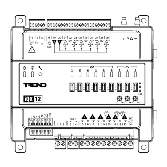
Labels used on IQX12
Caution, consult
!
documentation
24 Vac input
power connector
24 Vac AUX
output connector
Supply inputs for
digital outputs
Universal input
connector (UI)
Universal input/
output connector
(UI/AO)
Address switch
(future use only)
Dimensions
1
IQX12 Controller Installation Instructions TG201446 Issue 1, 26-Mar-2020
IQX12
Installation Instructions
(TG201446)
I/O Bus Connector
Sylk bus
connector
Differential
pressure sensor
20 Vdc AUX
output connector
Digital output
n
connector (DO)
Analogue output
override level
0
10V
Hand, off, auto
switch
135 mm (5.32")
138 mm (5.43")
Installation Instructions
GB
DE
DK
ES
PL
IT
NL
NO
https://partners.trendcontrols.com
4
Field Maintenance .........................................................8
5
Disposal .........................................................................8
6
China Hazardous Substance Table ..............................8
2
STORING
-20°C
+65°C
(-4°F)
(+150°F)
H O
Note: For temperatures below 0°C (32°F) special care must be
taken that there is no condensation on or within the unit.
It is recommended that the installation should comply
with the local electrical safety installation practices (e.g.
HSE Memorandum of Guidance on Electricity at Work
Regulations 1989, USA National Electric Code).
Any connected devices must be insulated from mains by
reinforced insulation.
WARNING Removal of cover exposes dangerous
voltages.
WARNING
To reduce the risk of electrical shock or fire
do not interconnect the output of different Class 2 circuits.
Power
Status
indicator
indicator
IQX12
Controller
FI
FR
SE
RU
95%RH
5
2
Service
button
Output status
indicators
48.5 mm (1.91")
60.4 mm (2.38")
1
Advertisement

Related Manuals for TREND IQX12


Summary of Contents for TREND IQX12
- Page 1 Hand, off, auto output connector switch (UI/AO) Power Status Service indicator indicator button Address switch Output status (future use only) indicators Dimensions 135 mm (5.32”) 48.5 mm (1.91”) 138 mm (5.43”) 60.4 mm (2.38”) IQX12 Controller Installation Instructions TG201446 Issue 1, 26-Mar-2020...
- Page 2 IP20 Mount Unit Either: Clip on to TS35 DIN Rail Or: Secure using screws and fixings 117 mm (4.69”) “click” 4 x M4 (No.8) Fit end stop if mounted on vertical rail IQX12 Controller Installation Instructions TG201446 Issue 1, 26-Mar-2020.
- Page 3 Sylk bus devices. Number of Devices: Up to 7 (subject to power loading - refer to device documentation). Sylk Device e.g. TR40, TR42. IQX12 IQX12 OVERRIDE polarity independent to additional Sylk devices IQX12 Controller Installation Instructions TG201446 Issue 1, 26-Mar-2020...
- Page 4 Tree / Star Topology Important: DO NOT ‘close’ the ring until RSTP has been configured on ALL devices in the ring. IQX12 IQX12 IQX12 IQX12 Configuration Manual Supervisor/ (TE201448) Web Browser IQX12 IQX12 IQX12 IQX12 IQX12 Controller Installation Instructions TG201446 Issue 1, 26-Mar-2020.
- Page 5 Loop powered (using 20 Vdc AUX output supply, 100mA maximum) ensure correct ensure correct polarity polarity Common C terminal is linked External internally to AUX supply common - Power no additional connection is required Supply IQX12 Controller Installation Instructions TG201446 Issue 1, 26-Mar-2020...
- Page 6 Output Signal Options: Binary (on/off); PWM (pulse width modulation) Connect Differential Pressure Sensor (IQX12P only, if required) Air, N2, O2 ±500 Pa non-condensing (± 2” WC) 0°C 50°C (32°F) (122°F) ø5.2mm ø3.5mm IQX12 Controller Installation Instructions TG201446 Issue 1, 26-Mar-2020.
- Page 7 Installation Instructions IQX12 INSTALLATION (continued) Install and Connect I/O Expansion Modules (if required) IQXIO Installation Instructions (TG201447) Configure the IQX12 Controller, I/O Modules & Sylk Bus Devices IQX Configuration Manual (TE201448) IQX12 Controller Installation Instructions TG201446 Issue 1, 26-Mar-2020...
- Page 8 Building Division of Honeywell Products and Solutions SARL, Z.A. La Pièce, 16, 1180 Rolle, Switzerland by its Authorized Representative, Trend Control Systems Limited. Trend Control Systems Limited reserves the right to revise this publication from time to time and make changes to the content hereof without obligation to notify any person of such revisions or changes.
Need help?
Do you have a question about the IQX12 and is the answer not in the manual?
Questions and answers