Table of Contents
Advertisement
Quick Links
Important: Retain these instructions
Contents
1
Unpacking
2
Storage
3
Installation Instructions
1 Unpacking
2 Storing
-10 °C-
14 °F
3 Installation Installation
1
Dimensions
160 mm (6.3")
J 8
CNC2 Installation Instructions TG200262 Issue 2, 2/10/08
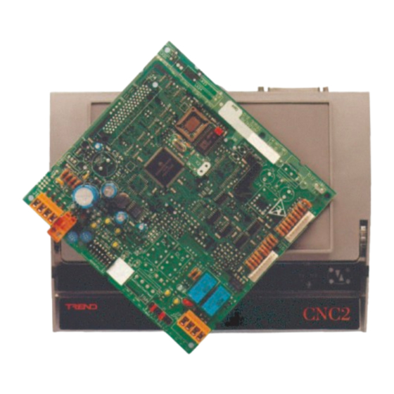
Communications Node Controller
1
1
1
J8
+50 °C
+122 °F
H O
2
E T 1
J 1 6
D e v B
J 1 5
D e v A
J 7
L a n A
33 mm
(1.3")
Installation Instructions
3.1 Installation Instructions - Mounting
4
Disposal
ET1
J16
Dev B
J15
Dev A
J7
Lan A
95 %RH
0
It is recommended that the installation should
comply with the HSE Memorandum of Guidance
on Electricity at Work Regulations 1989.
For USA install equipment in accordance with
National Electric Code.
WARNING: Opening the panel may expose dangerous
voltages.
417-IEC-5036
Caution: The CNC2 contains static sensitive devices.
Suitable anti-static precautions should be
taken throughout this operation to prevent
damage to the unit.
BS EN100015/1 Basic Specification: protection of
electostatic sensitive devices.
CNC2
1
5
8
CNC2 Installation
Instructions TG200262
1
Advertisement
Table of Contents

Related Manuals for TREND CNC2


Summary of Contents for TREND CNC2
- Page 1 D e v B voltages. J 1 5 417-IEC-5036 D e v A Caution: The CNC2 contains static sensitive devices. Suitable anti-static precautions should be taken throughout this operation to prevent damage to the unit. L a n A BS EN100015/1 Basic Specification: protection of 33 mm electostatic sensitive devices.
- Page 2 L a n A Lan A Dev A Dev A Lan A Lan A Mount the Node The CNC2 can be fitted into enclosures and controllers as shown in the table below: 151 mm (5.9”) 4 off 4 mm (0.16”) ...
- Page 3 J 1 5 10 Way, Molex, Female PC's links between pins 2-4, 3-5 D e v A COM port L a n A 9 Way, D type, Female 25 Way, D type, Female CABLE/EJ100179A001 CNC2 Installation Instructions TG200262 Issue 2, 2/10/08...
- Page 4 D e v B J 1 5 D e v A CNC2 I max = 150 mA 24 V L a n A Close Panel/Box Dev B Dev B Dev A Dev A Lan A CNC2 Installation Instructions TG200262 Issue 2, 2/10/08...
- Page 5 B a u d A L a n A Device B (J16) to local device Baud Rate = R2 e.g 19k2 = R2 = R2 CNC2 B a u d B B a u d A CNC2 Installation Instructions TG200262 Issue 2, 2/10/08...
- Page 6 CNC2 Check network cabling CNC2 Faulty for short circuits with a L A N A multimeter (NOT Megger) Check baud rate Power up other nodes until faulty node is found ). Correct fault. CNC2 Installation Instructions TG200262 Issue 2, 2/10/08...
- Page 7 Installation Instructions CNC2 3.2 Installation Instructions - Configuration (continued) Close panel/covers Check System temperature ? T=X °C Dev B Dev B Dev A Dev A Lan A CNC2 Lan A T=X °C CNC2 Installation Instructions TG200262 Issue 2, 2/10/08...
- Page 8 Division of Honeywell Technologies Sàrl, Ecublens, Route du Bois 3, Switzerland by its Authorized Representative, Trend Control Systems Limited. Trend Control Systems Limited reserves the right to revise this publication from time to time and make changes to the content hereof without obligation to notify any person of such revisions or changes.
Need help?
Do you have a question about the CNC2 and is the answer not in the manual?
Questions and answers