Table of Contents
Advertisement
Quick Links
Advertisement
Table of Contents

Related Manuals for AEMC 721


Summary of Contents for AEMC 721
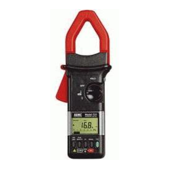
- Page 1 CLAMP-ON HARMONIC METER E N G L I S H User Manual...
-
Page 2: Table Of Contents
ABLE OF ONTENTS 1. INTRODUCTION ..............3 1.1 Receiving Your Shipment............4 1.2 Ordering Information..............4 2. PRODUCT FEATURES .............5 2.1 Description................5 2.2 Control Features ...............7 2.3 Digital Display Features............8 2.3.1 Display and Error Indications........9 3. SPECIFICATIONS ............10 3.1 Electrical Specifications ............10 3.2 General Specifications............12 3.3 Mechanical Specifications ............12 3.4 Safety Specifications ..............13 4. - Page 3 5.3 THD Push Button: Power Quality Measurements....29 5.3.1 %THD: Total Harmonic Distortion .......29 5.3.2 %DF: Distortion Factor ..........31 5.3.3 CF: Crest Factor ............32 5.3.4 Bargraph ..............32 5.4 Range Push Button: Manual Ranges ........33 5.5 Hz Push Button: Frequency Measurement......34 5.6 Peak/Smooth Push Button............35 5.6.1 Smooth ...............35 5.6.2...
-
Page 4: Introduction
In this manual, the symbol preceding instructions indicates that if the instructions are not followed, bodily injury, installation/sample and product damage may result. Risk of electric shock. The voltage at the parts marked with this symbol may be dangerous. Harmonic Meter Model 721... -
Page 5: Receiving Your Shipment
Save the damaged packing container to substantiate your claim. Ordering Information Harmonic Meter Model 721 ..........Cat. #1208.52 Includes a 9V battery, two 5 ft (1.5m) leads, two test probes, two grip probes, one insulated banana to BNC connector, a user manual and a hard carrying case. -
Page 6: Product Features
Beyond the absolute product ruggedness and overall design qualities —the Model 721 is built with GE Lexan and meets specific physical ® standards — the instrument features a high level of safety. The Model 721 meets IEC 1010-1 Category III for 600 V ratings. Harmonic Meter Model 721... - Page 7 The Model 721 is comfortable to hold, compact and easy to maneuver in crowded breaker panels. The hooked jaw design facilitates clamping and accommodates two 500 MCM conductors. The AEMC Harmonic Meter Model 721 works as easily as a clamp-on mul- timeter, while permitting True RMS voltage and current measurements.
-
Page 8: Control Features
Accepts two 500 MCM 2. Lever/Trigger Opens or closes jaws 3. Display Liquid crystal display, 9999 count 4. Min/Max Selects Record mode for A, V, %THD, %DF, CF, Hz Accesses the following values: Max, Min, AVG Harmonic Meter Model 721... -
Page 9: Digital Display Features
The combination digital/analog display gives measurements on a large 9999 count (33⁄4 digit) LCD display. A fast responding analog bargraph display provides indications for trends or surges. Displayed when instrument is measuring TRMS amperes Displayed when instrument is measuring TRMS voltage Harmonic Meter Model 721... -
Page 10: Display And Error Indications
Please note that the warning triangle will also be displayed if the input signals are too low, or if the fundamental signal is not 50 or 60Hz. Harmonic Meter Model 721... -
Page 11: Specifications
Basic Accuracy: 0.3 to 400.0 V: 1.5% R ± 4 cts 400.0 to 999.9 V: 1.5% R Crest Factor: >4.0 below 300 V Input Impedance: 1 MΩ, 47 pF Frequency Range: 15 Hz to 10 kHz Harmonic Meter Model 721... - Page 12 Minimum Input: 1 A or 1 V Accuracy: 0.5 Hz to 999.9 Hz: 0.1% R ± 1 ct 1000 Hz to 9999 Hz: 0.2% R ± 1 ct Display: Digital - Hz; Bargraph - True RMS (A or V) Harmonic Meter Model 721...
-
Page 13: General Specifications
LCD lens: Crystal Lexan 920A, UL 94 V1 ® Altitude: Operating: 2000 m (6500 ft) Storage: 5000 m (16,000 ft) Mechanical Specifications Envelope Protection: IEC 529: IP 40 Drop Test: IEC 68-2-32: 1m Vibration: IEC 68-2-6 Shocks: IEC 68-2-27 Harmonic Meter Model 721... -
Page 14: Safety Specifications
Non-destructive: 15 kV class 4 IEC 801-3: No influence: 3 V/m class 2 Minor influence: 10 V/m class 3 Transients: IEC 801-4: No influence: 2 kV class 4 Electric shocks: IEC 801-5: No influence: 1 kV class 3 Harmonic Meter Model 721... -
Page 15: Understanding Electrical Harmonics
It is becoming increasingly important to understand the fundamentals of harmonics, and to be able to recognize and monitor the presence of dam- aging harmonics. Harmonics within an electrical system vary greatly within different parts of the same distribution system and are not limited simply Harmonic Meter Model 721... - Page 16 AC signal into DC. The circuit draws current from the line only during the peaks of the voltage waveform, thereby charging a capacitor to the Peak of line voltage. The equipment DC requirements are fed from this capacitor and as a result the current waveform becomes distorted. Harmonic Meter Model 721...
- Page 17 In the factory environment, electronic power converters such as variable speed drives, SCR drives, etc., are the largest contributors to har- monic distortion. It is not uncommon to have THD levels as high as 25% within some industrial settings. Harmonic Meter Model 721...
- Page 18 These currents circulate within the delta primary causing overheating and shortened service life. ��������� ����������� � �� � �� ������� ��������� �� � ������� Delta Primary, Circulating Current Harmonic Meter Model 721...
- Page 19 False tripping of circuit breakers is also a problem encountered with the higher frequencies that harmonics produce. Peak sensing circuit breakers often will trip even though the amperage value has not been exceeded. Harmonic current Peak values can be many times higher than sinusoidal waveforms. Harmonic Meter Model 721...
- Page 20 IEC-555. Mathematically, %DF is the ratio of the root-mean-square(RMS) of the harmonic content to the root-mean-square (RMS) value of the total signal, and expressed as a percentage. Harmonic Meter Model 721...
-
Page 21: Detection And Measurement
If excessive amounts of triplen harmonics are present in the neutral, neutral current may exceed phase current. Consult the NEC for the maximum ampacity for each of ® the conductors that have been tested. Harmonic Meter Model 721... -
Page 22: Effects On The System
Depending on the frequency, the motor will rotate in the oppo- site direction (counter-torque). The fifth harmonic, which is very prevalent, is a negative sequence harmonic causing the motor to have a backward rotation, shortening the service life. Harmonic Meter Model 721... -
Page 23: Transformer Derating
An alternate method for derating transformers is available for buildings which supply single-phase, 120 V receptacles. This method is established by The Computer & Business Equipment Manufacturers Association (CBEMA). 1.414 CBEMA Derating Factor = Crest Factor Harmonic Meter Model 721... -
Page 24: Meter Readings
The higher the factor, the more capable the instrument of measuring a complex waveform correctly. When harmonics are present crest ���������������� factors may be less than (CF of a square ������������������������� wave = 1) or greater than 1.414. Harmonic Meter Model 721... -
Page 25: Limiting The Effects Of Harmonics
In the future, systems may be available which will offset harmonics by applying signals that are equal in amplitude but opposite in phase, thereby canceling or severely limiting harmonic effects. ����� � � � ������� �������� � ���� ������������������������� Harmonic Meter Model 721... -
Page 26: Operation
RMS value exceeds 700 A. The warning symbol may also be displayed if the input signal is too low (<50 mA) or if the fundamental signal is not 50 or 60 Hz. Harmonic Meter Model 721... -
Page 27: Ranging
Please note that the analog bargraph will continue to display RMS cur- rent values while other measurement functions are displayed (e.g. %THD, %DF, CF, Hz, Min/Max, Smooth, Peak). The bargraph ranges are 60 Arms and 600 Arms. Harmonic Meter Model 721... -
Page 28: Voltage Measurements
RMS value exceeds 600 V. The warning symbol may also be displayed if the input signal is too low (<50 mV) or if the fundamental is not 50 or 60 Hz. Harmonic Meter Model 721... -
Page 29: Ranging
Please note that the analog bargraph will continue to display RMS volt- age values while other measurement functions are displayed (e.g. %THD, %DF, CF, Hz, Min/Max, Smooth, Peak). The bargraph ranges are 60 Vrms and 600 Vrms. Harmonic Meter Model 721... -
Page 30: Thd Push Button: Power Quality Measurements
%THD, is the ratio of the root- mean-square (RMS) of the harmonic content to the root-mean-square (RMS) value of the fundamental, and expressed � ��� � as a percentage (see p. 16 for details). Harmonic Meter Model 721... - Page 31 (RMS) – (Fundamental) Example: The Model 721 measures a RMS value of 230 Amps and THD of 130%. This means that the harmonic content is 130% of the fundamental. Calcu- late for Total Harmonic current by solving the equations: �...
-
Page 32: Df: Distortion Factor
(see p. 20 for details). %DF Application Example: The Model 721 measures an RMS value of 100 A and a DF of 30%. The math- ematics below show how to figure out the Harmonic and Fundamental current: �... -
Page 33: Cf: Crest Factor
Please note that the analog bargraph will continue to display Arms or Vrms while THD function measurement values (%THD, %DF, CF) are displayed. The Range button only changes the bargraph ranges while in the THD function. Harmonic Meter Model 721... -
Page 34: Range Push Button: Manual Ranges
3 seconds. The displayed RANGE indicator will disappear, confirmed with an audible tone. The bargraph ranges are 60 Vrms and 600 Vrms, and are also manually selected. The analog bargraph will continue to display present values while other measurement functions are displayed. Harmonic Meter Model 721... -
Page 35: Hz Push Button: Frequency Measurement
Button, § 5.6). MIN/MAX is active in Hz (see MIN/MAX Push Button, § 5.7). If while measuring frequency on a 60 Hz system, the Model 721 indicates 180 Hz, then the third harmonic is dominant and exceeds the fundamental in magnitude. This may occur in office settings on single-phase loads or on lighting ballasts. -
Page 36: Peak/Smooth Push Button
In ��������� ���� �������������� � � � � � � � � � � � this mode, the Model 721 calculates and ������ displays a three-second average reading. ��� Smooth may be used in Volts, Amps, Fre- �... -
Page 37: Peak
Note: The same operations apply with SMOOTH turned on Recording is initiated with the MIN/MAX push button during the selected measurement function. RECORD indication will blink 1/second during the record mode. Control is verified with a short beep. Harmonic Meter Model 721... - Page 38 MIN and MAX values. In MIN/MAX Recording, the bargraph indicates Arms or Vrms. The MIN and MAX values are also indicated and blink. Harmonic Meter Model 721...
-
Page 39: Vout - Analog Output
The beep will indicate the mode change and the displayed RECORD symbol will disappear. – Analog Output When measuring current or current power quality, the Model 721 automati- cally provides an analog output (1 mV/A or 10 mV/A) through the voltage terminals. -
Page 40: Output Level
6. Adjust the oscilloscope range for the desired waveform size and dis- play. Readings from the Model 721 are also valid. The analog output is preset to 1 mV/A at the factory and permits current measurements from 50 mA to 700.0 Arms, and to 999.9 A Peak. -
Page 41: Auto-Off Feature
5.10 Auto-Off Feature The Model 721 will automatically shut itself off after 10 minutes during the following conditions: • No push button action • No rotary switch (A ,V) action • No measurement change • Not in Record Min/Max mode A short beep will be heard prior to shutdown. -
Page 42: Maintenance
• To avoid electrical shock and/or damage to the probe, do not get water or other foreign agents into the case. Turn the Model 721 OFF and discon- nect the meter from all circuits and inputs before opening the case. -
Page 43: Battery Replacement
6. Replace the back cover, noting that it slips beneath the hold-down lip and fits securely into position. Take care to position any loose wire or circuit correctly before closing. 7. Install and tighten the three screws. �� �������� ����������� ����������������� ������������ ������������� Harmonic Meter Model 721... -
Page 44: Repair And Calibration
® Chauvin Arnoux , Inc. ® d.b.a. AEMC Instruments 200 Foxborough Boulevard Foxborough, MA 02035, USA Phone: (800) 343-1391 (508) 698-2115 Fax: (508) 698-2118 techsupport@aemc.com www.aemc.com NOTE: Do not ship Instruments to our Foxborough, MA address. Harmonic Meter Model 721... -
Page 45: Limited Warranty
Limited Warranty The Model 721 is warranted to the owner for a period of two years from the date of original purchase against defects in manufacture. This limited warranty is given by AEMC Instruments, not by the distributor from whom it was ®... - Page 46 08/18 99-MAN 100066 v3 Chauvin Arnoux ® , Inc. d.b.a. AEMC ® Instruments 15 Faraday Drive • Dover, NH 03820 USA • Phone: (603) 749-6434 • Fax: (603) 742-2346 www.aemc.com • www.chauvin-arnoux.com...
Need help?
Do you have a question about the 721 and is the answer not in the manual?
Questions and answers