Keysight U8903A User Manual
Audio analyzer
Hide thumbs
Also See for U8903A:
- Quick start manual (33 pages) ,
- Demo manual (16 pages) ,
- How to do (16 pages)
Table of Contents

Related Manuals for Keysight U8903A


Summary of Contents for Keysight U8903A
- Page 1 Keysight U8903A Audio Analyzer Notice: This document contains references to Agilent. Please note that Agilent’s Test and Measurement business has become Keysight Technologies. For more information, go to www.keysight.com. User’s Guide...
- Page 2 DOCUMENT OR OF ANY INFORMATION Software. The EULA and the license set CONTAINED HEREIN. SHOULD Printed in Malaysia forth therein, does not require or KEYSIGHT AND THE USER HAVE A Published by: permit, among other things, that SEPARATE WRITTEN AGREEMENT Keysight: (1) Furnish technical...
- Page 3 Caution, risk of danger (refer to this Earth (ground) terminal manual for specific Warning or Caution information) Protective conductor terminal Caution, hot surface Frame or chassis terminal Out position of a bi-stable push control Equipotentiality In position of a bi-stable push control Keysight U8903A User’s Guide...
- Page 4 To avoid the occurrence of additional hazards, do not install substitute parts or perform any unauthorized modification to the product. Return the product to Keysight for service or repair to ensure that the safety features are maintained. Keysight U8903A User’s Guide...
- Page 5 – Always use dry cloth to clean the device. Do not use ethyl alcohol or any other volatile liquid to clean the device. – Do not permit any blockage of the ventilation holes of the device. Keysight U8903A User’s Guide...
- Page 6 Storage temperature –40 °C to 70 °C Storage humidity 20% to 80% RH noncondensing at 65 °C The U8903A Audio Analyzer complies with the following safety and EMC CAUTION requirements. – IEC 61010-1:2001/EN 61010-1:2001 (2nd Edition) – Canada: CAN/CSA-C22.2 No. 61010-1-04 –...
- Page 7 Cet appareil ISM est conforme a la this electrical/electronic product in norme NMB-001 du Canada. domestic household waste. The CSA mark is a registered trademark of the Canadian Standards Association. Keysight U8903A User’s Guide...
- Page 8 To return this unwanted instrument, contact your nearest Keysight Service Center, or visit http://about.keysight.com/en/companyinfo/environment/takeback.shtml for more information. Sales and Technical Support To contact Keysight for sales and technical support, refer to the support links on the following Keysight websites: – www.keysight.com/find/U8903A (product-specific information and support, software and documentation updates) –...
- Page 9 This chapter also contains instructions on how to install and configure the U8903A. Operation and Features This chapter describes the operation and features that are offered by the U8903A, such as test capabilities, key features, and front panel menu operation. Instrument Configuration This chapter guides you through the configuration of the U8903A input and output settings for optimum measurement results.
- Page 10 THIS PAGE HAS BEEN INTENTIONALLY LEFT BLANK. Keysight U8903A User’s Guide...
-
Page 11: Table Of Contents
....... .33 Power On the U8903A ........34 Preset . - Page 12 ........108 Keysight U8903A User’s Guide...
- Page 13 ......... . .151 Keysight U8903A User’s Guide...
- Page 14 Appendix E: Spot Parameters ....... 166 Keysight U8903A User’s Guide...
- Page 15 ....... .62 Figure 2-14 File Manager menu for saving the U8903A state ..63...
- Page 16 ....115 Figure 5-6 Function 2 selection fourth page ....116 Keysight U8903A User’s Guide...
- Page 17 ........150 Figure 7-8 I/O settings page ......151 Keysight U8903A User’s Guide...
- Page 18 THIS PAGE HAS BEEN INTENTIONALLY LEFT BLANK. Keysight U8903A User’s Guide...
- Page 19 List of Tables Table 1-1 U8903A front panel description ....25 Table 1-2 U8903A rear panel description ....28...
- Page 20 THIS PAGE HAS BEEN INTENTIONALLY LEFT BLANK. Keysight U8903A User’s Guide...
- Page 21 Product at a Glance Front Panel LCD Display Product Dimensions Standard Accessories Optional Accessories Installation and Configuration Maintenance Power On the U8903A Preset Help System This chapter provides an overview of the outlook and installation of the U8903A audio analyzer.
-
Page 22: Getting Started
U8903A can be configured for up to eight channels, however this feature is only applicable in future releases. The U8903A is provided with a set of features as listed below which allows you to perform a wide range of audio parameter measurements. The U8903A also supports industrial standard instrument connectivity such as GPIB, USB, and LAN. - Page 23 – Digital filters such as low pass, high pass, and weighting filters – Input autoranging – Selectable measurement bandwidth – Selectable measurement time – Free Run or External trigger mode To search for software/firmware updates for your product, go to the Keysight Technical Support website at www.keysight.com/find/TechSupport. Keysight U8903A User’s Guide...
-
Page 24: Lxi Class-C Compliant Audio Analyzer
Getting Started LXI Class-C Compliant Audio Analyzer The U8903A audio analyzer is an LXI Class C compliant instrument, developed using LXI Technology. LXI, an acronym for LAN eXtension for Instrumentation, is an instrument standard for devices that use the Ethernet (LAN) as their primary communication interface. -
Page 25: Product At A Glance
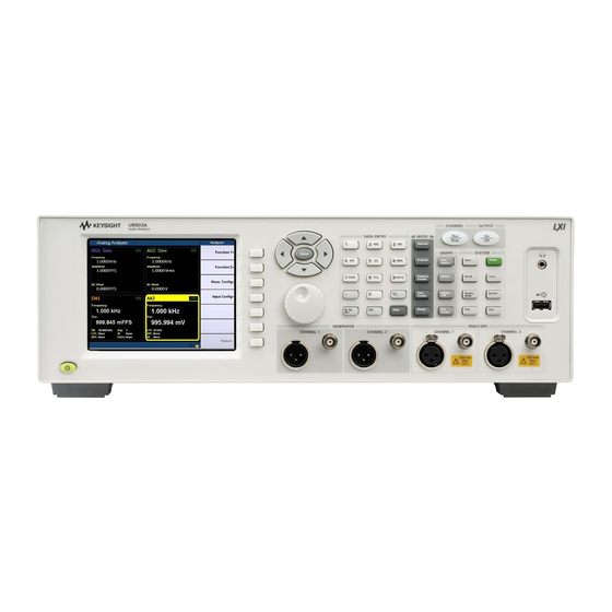
U8903A front panel Table 1-1 U8903A front panel description Item Display Description LCD display Provides information on the current function including status indicators, settings, and error messages Item Description Power on/off Turns the U8903A on or off Keysight U8903A User’s Guide... - Page 26 Enables access to the graph functions including peak navigation and marker function. You can also use the Full Screen function to maximize the display area. Mode Enables access to the U8903A core functions Data Entry Contains alphanumeric and editing keys to enter values or text, or modify the...
-
Page 27: Figure 1-2 U8903A Rear Panel
Getting Started Table 1-1 U8903A front panel description (continued) Item Connector Description Generator output Outputs an audio signal to the unit-under-test (UUT). A XLR male output connector and a BNC female output connector are provided for each channel. Analyzer input Accepts an audio signal from the UUT. -
Page 28: U8903A Rear Panel Description
LAN interface Allows Ethernet LAN communication through a 10/100 Base-T LAN cable. Recommended to use a shielded LAN cable. VGA interface Allows the U8903A to be connected to an external monitor Fuse Fuse compartment for AC supply AC power Receptacle for AC line voltage connection... -
Page 29: Front Panel Lcd Display
Getting Started Front Panel LCD Display The U8903A displays the analyzer view upon power-up, as shown in the following figure. Measurement status Softkey menu Measurement results Active channel Function 1 Function 2 Analyzer settings Channel 2 Status display USB status... -
Page 30: Product Dimensions
Getting Started Product Dimensions Top view 425.60 mm (16.76 in) 405.00 mm (15.94 in) Front view 133.60 mm (5.25 in) Keysight U8903A User’s Guide... -
Page 31: Standard Accessories
Getting Started Standard Accessories Verify that you have received the following items with your U8903A. If anything is missing or damaged, please contact the nearest Keysight Sales Office. – Power cord – Shielded LAN cable – USB cable – USB flash storage device –... -
Page 32: Installation And Configuration
If any damage is found, notify the nearest Keysight Sales Office immediately. Keep the original packaging in case the U8903A has to be returned to Keysight in future. If you return the U8903A for service, attach a tag identifying the owner and model number. -
Page 33: Maintenance
Getting Started Maintenance Fuse removal/replacement This section contains the information for replacing the U8903A rear panel AC line fuse. Ensure that you are using the quick-acting, low-breaking capacity 5 A/250 V fuse. NOTE Perform the following procedure to replace the fuse. -
Page 34: Power On The U8903A
Getting Started Power On the U8903A Connect one end of the power cord to the U8903A rear panel AC power inlet, and the other end to an AC voltage source. Ensure that the provided power cord matches the country of origin as shown in the table below. The U8903A will automatically adjust to the correct line voltage in the range of 100 Vac to 240 Vac. -
Page 35: Preset
A preset does not erase the flash memory, state memory, or I/O configuration. A preset will delete all customized settings on the U8903A. To preset the U8903A, you can perform either one of the following steps. – Send the *RST, SYSTem:PRESet, SYSTem:RESet[:MODE], or SYSTem:RESet:CHANnel SCPI commands from the PC via the USB, GPIB, or LAN interface. -
Page 36: Help System
. To deactivate, press When Help is enabled, the function keys will not execute their normal functions when pressed. An example of a help dialog information is shown as follows. Figure 1-4 Help dialog information example Keysight U8903A User’s Guide... - Page 37 Keysight U8903A Audio Analyzer User’s Guide Operation and Features Test Capabilities Key Features Front Panel Operation Editing Keys This chapter describes the operation and features that are offered by the U8903A, such as test capabilities, key features, and front panel menu operation.
-
Page 38: Operation And Features
U8903A to test devices with stereo capability. The U8903A audio generator has a frequency range of 5 Hz to 80 kHz. Its sine waveform amplitude range is from 0 Vrms to 8 Vrms (11.3 Vp) for the Unbalanced or Common mode test output configuration, and 0 Vrms to 16 Vrms (22.6 Vp) for... - Page 39 – Multitone generation – User-defined arbitrary waveform The U8903A audio analyzer has a frequency measurement range of 10 Hz to 100 kHz, as well as an amplitude measurement range of microvolts to 200 Vp (140 Vrms). Below is the list of the audio analyzer features.
-
Page 40: Key Features
– LAN – USB These three interfaces make the U8903A a highly flexible instrument. Furthermore, the LAN interface also enables you to view and modify the U8903A LAN configuration via a Web page. Sweep function The U8903A can perform sweeps and the results are displayed on the LCD display. -
Page 41: Digital Filters
Operation and Features Digital filters The U8903A has a series of filters that are implemented digitally. They consist of low pass, high pass, and weighting filters such as CCITT, CCIR, C-Message, and A-Weighting. The U8903A also allows user-defined filters to be uploaded to the device. You need to specify the filter parameters comprising filter type, group delay, and coefficients/sections. -
Page 42: Front Panel Operation
The front panel keys are organized in groups based on their functions as follows. – Mode – Graph – System – Softkeys – Controls – Data Entry – Navigation keys – Knob Mode This group provides quick access to the main functions. Figure 2-1 Mode panel Keysight U8903A User’s Guide... -
Page 43: Mode Panel Key Description
Arbitrary. The third section of the menu tree displays the Output Settings, Frequency, Amplitude, and DC Offset functions. Use the softkey on the right side of the LCD display to navigate to the next menu level. Keysight U8903A User’s Guide... -
Page 44: Figure 2-2 Generator: Waveform (Sine, Variable Phase, And Dual Sine) Menu Tree
You are only allowed to set DC Offset the Upper Freq values for Upper/Center DFD IEC 60118 and Center Freq values for DFD IEC Amplitude 60268 DC Offset Figure 2-2 Generator: Waveform (Sine, Variable Phase, and Dual Sine) menu tree Keysight U8903A User’s Guide... -
Page 45: Figure 2-3 Generator: Waveform (Noise, Dc, Multitone, Square, And Arbitrary) Menu Tree
Amplitude Output Settings Tones Frequency Multiplier Amplitude DC Offset Phase Mode Preview Arbitrary Waveform Output Settings Amplitude DC Offset Recall File Save File Preview Figure 2-3 Generator: Waveform (Noise, DC, Multitone, Square, and Arbitrary) menu tree Keysight U8903A User’s Guide... -
Page 46: Figure 2-4 Generator: Output Settings, Frequency, Amplitude, And Dc Offset Menu Tree
For Balanced or Common mode output connection, impedance selection is 100 Ω and 600 Ω. For Unbalanced output connection, impedance selection is 50 Ω and 600 Ω. Figure 2-4 Generator: Output Settings, Frequency, Amplitude, and DC Offset menu tree Keysight U8903A User’s Guide... -
Page 47: Table 2-4 Table
Refer to Output Settings SMPTE IMD 10:1 Upper Freq Enter the upper frequency value Lower Freq Enter the lower frequency value Amplitude Enter the composite signal amplitude value DC Offset Enter the signal DC offset value Keysight U8903A User’s Guide... -
Page 48: Table 2-6 Table
Enter the signal fundamental frequency value Amplitude Enter the signal amplitude value Tones Enter the number of frequency components, from 2 to 60 Multiplier Enter the frequency multiplier DC Offset Enter the signal DC offset value Keysight U8903A User’s Guide... - Page 49 For Unbalanced mode output connection, the impedance selection is 50 Ω and 600 Ω. Ref. Imp Enter the reference impedance value Frequency Enter the signal frequency value Amplitude Enter the signal amplitude value DC Offset Enter the signal DC offset value Keysight U8903A User’s Guide...
-
Page 50: Figure 2-5 Analyzer Function Menu Tree
Gen Track, 1/128 s, 1/64 s, 1/32 s, Meas Time 1/16 s, 1/8 s, 1/4 s, 1/2 s, 1 s DFD 60118 3rd Trigger Free Run, External Phase Avg. Points Ref/Rel Refer to the Ref/Rel menu tree Figure 2-5 Analyzer function menu tree Keysight U8903A User’s Guide... -
Page 51: Figure 2-6 Analyzer: Units Menu Tree
The analyzer function menu tree for Units is shown as follows. Analyzer Function 1 Units If function type is Frequency Function 2 ΔHz If function type is Amplitude ΔdB If function type is Ratio ° If function type is Phase Figure 2-6 Analyzer: Units menu tree Keysight U8903A User’s Guide... -
Page 52: Figure 2-7 Analyzer: Ref/Rel Menu Tree
Meas > Lvl Rel If Meas. Type is Level Linear Meas > Frq Ref If Meas. Type is Frequency Delta Meas > Ratio Ref If Meas. Type is Ratio Delta Figure 2-7 Analyzer: Ref/Rel menu tree Keysight U8903A User’s Guide... - Page 53 Select the second measurement parameter Noise Level SINAD THD + N Ratio THD + N Level Crosstalk (Ch Driv) Crosstalk (Ch Meas) SMPTE IMD DFD 60268 2nd DFD 60268 3rd DFD 60118 2nd DFD 60118 3rd Phase Keysight U8903A User’s Guide...
-
Page 54: Table 2-8 Table
Select either Balanced or Unbalanced input connection Unbalanced Range Auto Select the input range 400 mV to 140 V Frequency Lock Auto Select the fundamental frequency lock method for SINAD, THD Level, and THD Ratio measurement Gen. Lock Keysight U8903A User’s Guide... - Page 55 Set the ratio reference value Meas > Lvl Rel Select either Off, Log, or Linear Linear Meas > Frq Ref Select either Off or Delta Delta Meas > Ratio Ref Select either Off or Delta Delta Keysight U8903A User’s Guide...
-
Page 56: Figure 2-8 Frequency And Time Domain Menu Trees
Auto Scale, Auto Scale X, Auto Scale Y Harmonics/Graph View Not applicable Hold Channel 1 None Continuous, Running Mode Channel 2 Single Input Settings Save Pts to File Figure 2-8 Frequency and time domain menu trees Keysight U8903A User’s Guide... -
Page 57: Graph (Frequency/Time Domain) Menu Description
Single to stop the Single measurements. Input Settings Select the channel, measurement bandwidth, input connection, input range, AC/DC coupling, and trigger settings. Save Pts to File Saves the graph points to a file. Keysight U8903A User’s Guide... -
Page 58: Figure 2-9 Sweep Function Menu Tree
Axis Settings Auto Scale Enter the graph axis values and spacing type. You can also choose to perform autoscaling. Auto Scale X Auto Scale Y Keysight U8903A User’s Guide... -
Page 59: Graph Functions
Save Pts to File Saves the sweep points to a file. Load Pts to List Loads the sweep points from a file Graph functions This group provides quick access to the commonly used graph functions. Figure 2-10 Graph panel Keysight U8903A User’s Guide... -
Page 60: Run/Stop And On/Off
Maximizes the graph view to the full display size Run/Stop and On/Off For generator or analyzer, you can select a channel by pressing the arrow keys on the U8903A front panel. Toggling on the front panel will start or stop signal generation on a generator channel or measurements on an analyzer channel. -
Page 61: Figure 2-12 Channel Selection And Status
Selected channel Figure 2-12 Channel selection and status When the selected analyzer channel is in Run mode, the U8903A will take continuous readings as fast as possible based on the specified measurement time. Pressing while in the Run mode will stop the measurements for the selected analyzer channel. -
Page 62: System
Operation and Features System The U8903A provides access to some useful system functions located on the System panel as shown in the following figure. Figure 2-13 System panel The description for each key on the System panel is shown in the following table. -
Page 63: Figure 2-14 File Manager Menu For Saving The U8903A State
Operation and Features Save This function saves the current U8903A state to a file. You have the option to save the U8903A state for a single channel or whole module. When is pressed in the sweep, analyzer, or generator mode, you may select either the selected channel or whole module to save the U8903A state. -
Page 64: Figure 2-15 File Manager Menu For Recalling The U8903A State
Operation and Features Recall This function recalls a saved U8903A state from a file in either the U8903A internal memory or a USB external flash storage. The File Manager will be launched once is pressed. Figure 2-15 File Manager menu for recalling the U8903A state Press Source to select a saved U8903A state file in either the U8903A internal memory or a USB external flash storage. -
Page 65: Figure 2-16 Analyzer-Generator Display
The analyzer-generator display is shown as follows. This display is only available in the analyzer mode. Figure 2-16 Analyzer-generator display Keysight U8903A User’s Guide... -
Page 66: Figure 2-17 Analyzer 8-Channel Display
– Selected channel (only applicable for the sweep, analyzer, or generator mode) – Selected module – All modules without deleting the user-defined files – Whole system including deletion of the user-defined files. Local This function returns the U8903A to local operation from the remote mode. Keysight U8903A User’s Guide... -
Page 67: Figure 2-18 System Function Menu Tree
Select All, Deselect All, Secure Erase Cancel All Card 1 Power-Up State Default Last Settings Help Language English (US) Mode Japanese Key Sound Channel French Left Filter HP8903B Config German Right Filter Figure 2-18 System function menu tree Keysight U8903A User’s Guide... - Page 68 Performs a self-test on a particular section of the U8903A Diagnostic Front Panel Performs a diagnostic test on the U8903A front panel. You can verify whether a key is functional by observing the change of color for the pressed key.
-
Page 69: Table
Power-Up Default Sets the U8903A to its default power-on State state Last Settings Sets the U8903A to its previous setting mode upon power up Help Language English (US) Sets the language to English Japanese Sets the language to Japanese French... - Page 70 – Large data (32K graph data or image capture using SYST:DISP:IMAG? command) are not able to be acquired using the GPIB interface. – GPIB response is slower in HP8903B mode. For more information on the system functions, refer to the U8903A Audio NOTE Analyzer Instrument Help File.
-
Page 71: Editing Keys
Operation and Features Editing Keys The editing keys consist of the left navigation keys and right input keys as shown in the following figure. Figure 2-19 Editing function keys Keysight U8903A User’s Guide... -
Page 72: Editing Key/Control Description
Enter alphanumeric data by using the number keys and decimal point, or select the channel number in analyzer mode Enter Confirms an entry Arrow keys Use the arrow keys to select a channel, and highlight or navigate the editable items on the LCD display for editing Keysight U8903A User’s Guide... - Page 73 Keysight U8903A Audio Analyzer User’s Guide Instrument Configuration U8903A Block Diagram Input Settings Common Settings Ref/Rel Output Settings This chapter describes how to configure the U8903A inputs and outputs to obtain the optimum measurement results for your application.
-
Page 74: Instrument Configuration
Figure 3-1 U8903A block diagram The description for the U8903A block diagram is provided as follows. Measurement An audio signal can enter the analyzer through either the Balanced (XLR) or Unbalanced (BNC) input signal connector. The audio signal then passes through the AC/DC coupling circuit. - Page 75 (DAC) where it is converted to voltage and sent to the output conditioning block to be amplified or attenuated to the required amplitude. Finally, the waveform is routed through either the Balanced (XLR) or Unbalanced (BNC) output signal connectors to the unit-under-test (UUT). Keysight U8903A User’s Guide...
-
Page 76: Input Settings
Instrument Configuration Input Settings The U8903A analyzer inputs can be configured with selectable AC/DC coupling, AC level detector, digital filters, Unbalanced/Balanced input connections, and measurement ranges as shown in the following figure. Figure 3-2 Analyzer input settings Keysight U8903A User’s Guide... -
Page 77: Ac/Dc Coupling
AC component of a signal, for example, when making RMS or peak-to-peak voltage measurements. The AC/DC coupling selection is shown as follows. Figure 3-3 AC/DC coupling selection Keysight U8903A User’s Guide... -
Page 78: Ac Level Detection
The Peak-to-Peak detector returns the peak-to-peak voltage, while the Quasi Peak detector provides a response conforming to the CCIR-468 specification for noise measurements. This detector is usually used together with the CCIR-1k weighted filter. Figure 3-4 AC level detector selection Keysight U8903A User’s Guide... -
Page 79: Digital Filters
Up to three filters, one from each type, can be applied to the signal simultaneously. The U8903A also allows user-defined filters to be uploaded to the device. Refer to “Appendix C:... -
Page 80: Input Configuration
The Unbalanced configuration selects the front panel BNC connectors as the input source. The signal in the inner conductor of the coaxial connector is referenced to ground for measurement. Figure 3-6 Input signal connector configuration Keysight U8903A User’s Guide... -
Page 81: Input Ranging
– 400 mV – 800 mV – 1.6 V – 3.2 V – 6.4 V – 12.8 V – 25 V – 50 V – 100 V – 140 V Keysight U8903A User’s Guide... -
Page 82: Frequency Lock
Frequency if the frequency lock type is Auto. When the frequency lock type is set to Gen. Lock, the fundamental frequency is determined by the frequency value set at the corresponding generator channel. Figure 3-7 Frequency lock Keysight U8903A User’s Guide... -
Page 83: Common Settings
Common settings Measurement bandwidth The U8903A has two settings for measurement bandwidth. The low bandwidth mode has a maximum measurement bandwidth of 30 kHz, while the high bandwidth mode can measure signals with frequencies up to 100 kHz. The low bandwidth mode is the default setting with better residual noise and distortion performance. -
Page 84: Measurement Time
This is useful when making sweep measurements as the measurement time will be optimized for fast sweeps. However, Gen Track works only if the signal is looped back from the U8903A output to its input. Keysight U8903A User’s Guide... -
Page 85: Figure 3-10 Measurement Time Selection
Instrument Configuration The measurement time selection is shown as follows. Figure 3-10 Measurement time selection first page Figure 3-11 Measurement time selection second page Keysight U8903A User’s Guide... -
Page 86: Trigger
If External triggering is set, the analyzer waits for a trigger pulse on the Trigger In connector of the rear panel before acquiring the measurement data. The figure below shows the trigger setting selection of the analyzer. Figure 3-12 Trigger settings selection Keysight U8903A User’s Guide... -
Page 87: Average Points
The default average points setting is 1. This sets the number of readings used for averaging. Higher number of average points should be used when the analyzed data is noisy. The figure below shows the average points setting selection of the analyzer. Figure 3-13 Average points selection Keysight U8903A User’s Guide... -
Page 88: Ref/Rel
There are three available types consisting of Level, Frequency, and Ratio. For the relative level values, the level measurement can be displayed in Off mode, Log mode (dBr), or Linear mode (x). Figure 3-14 Reference Level Keysight U8903A User’s Guide... -
Page 89: Figure 3-15 Reference Frequency
For the reference frequency values, the frequency measurement can be displayed in Off mode (Hz) or Delta mode (ΔHz). Figure 3-15 Reference Frequency For the reference ratio values, the ratio measurement can be displayed in Off mode or Delta mode (ΔdB). Figure 3-16 Reference Ratio Keysight U8903A User’s Guide... -
Page 90: Output Settings
Instrument Configuration Output Settings The U8903A generator output settings can be configured using selectable output connections, impedances, and reference impedances as shown in the figure below. Figure 3-17 Output settings Output type The output connection can be set to Balanced, Unbalanced, or Common mode. -
Page 91: Output Impedance
Unbalanced: 50 Ω, 600 Ω Reference impedance The reference impedance can be set as shown in the figure below. The impedance is used for conversion of the measurement result in unit W or dBm. Figure 3-18 Reference impedance Keysight U8903A User’s Guide... - Page 92 Instrument Configuration THIS PAGE HAS BEEN INTENTIONALLY LEFT BLANK. Keysight U8903A User’s Guide...
-
Page 93: Audio Generator Functions
Keysight U8903A Audio Analyzer User’s Guide Audio Generator Functions Audio Generator This chapter describes the procedure to generate the U8903A audio test signals. -
Page 94: Audio Generator
– Dual – SMPTE IMD 1:1 – SMPTE IMD 4:1 – SMPTE IMD 10:1 – DFD IEC 60118 – DFD IEC 60268 – Noise – Gaussian – Rectangular – DC – Multitone – Square – Arbitrary Keysight U8903A User’s Guide... -
Page 95: Figure 4-1 Generator Waveform Selection
The generator waveform selection is shown as follows. Figure 4-1 Generator waveform selection Press More (1/2) to display more generator waveform selection as follows. Figure 4-2 More generator waveform selection To select the desired waveform or signal, press the corresponding softkey. Keysight U8903A User’s Guide... -
Page 96: Sine Waveform
Amplitude can be expressed as Vrms, Vpeak, Vpp, or dBV. For a perfect sine waveform without any DC offset, Vpp is twice Vpeak, while Vrms is equivalent to Vpeak/√2. The DC offset refers to the DC component of the waveform. Keysight U8903A User’s Guide... -
Page 97: Variable Phase Waveform
Variable phase waveforms are useful for measuring the phase difference or timing skew between the channels of a multiple channel audio system. To select the variable phase waveform, press Waveform > Variable Phase. Keysight U8903A User’s Guide... -
Page 98: Dual Sine Waveform
The dual sine waveform group allows you to generate a composite waveform that is the summation of two independent sine waveforms. Dual sine waveforms are useful in testing the intermodulation distortion characteristics of an audio system. To select a dual sine waveform, press Waveform > Dual Sine. Keysight U8903A User’s Guide... -
Page 99: Figure 4-6 Dual Sine Waveform Selection
Audio Generator Functions The following figure shows the dual sine waveform selection. Figure 4-6 Dual sine waveform selection Dual waveform You can select a generic dual sine waveform as follows. Figure 4-7 Dual waveform menu Keysight U8903A User’s Guide... -
Page 100: Figure 4-8 More Dual Sine Waveform Parameters
Frequency 1 is the frequency of the first sine component. Frequency 2 is the frequency of the second sine component. Amplitude refers to the amplitude of the composite signal. Ratio refers to the amplitude ratio of the second component over the first component. Keysight U8903A User’s Guide... -
Page 101: Figure 4-9 Smpte Imd Waveform Menu
Figure 4-9 SMPTE IMD waveform menu The SMPTE IMD waveform may be configured with the following parameters. – Upper Frequency – Lower Frequency – Amplitude – DC Offset Amplitude refers to the amplitude of the composite signal. Keysight U8903A User’s Guide... -
Page 102: Figure 4-10 Dfd Iec 60118 Waveform Menu
DFD IEC 60118 waveform menu The DFD IEC 60118 waveform may be configured with the following parameters. – Difference Frequency – Upper Frequency – Amplitude – DC Offset Amplitude refers to the amplitude of the composite signal. Keysight U8903A User’s Guide... -
Page 103: Figure 4-11 Dfd Iec 60268 Waveform Menu
– DC Offset Amplitude refers to the amplitude of the composite signal. Refer to “Appendix A: SMPTE IMD and DFD Default Settings” on page 158 for the NOTE default settings of both SMPTE IMD and DFD waveforms. Keysight U8903A User’s Guide... -
Page 104: Noise Signals
To select the noise signal, press Waveform > Noise. You can select either a Gaussian or Rectangular noise signal as shown in the following figure. Figure 4-12 Noise signal selection The Gaussian noise signal menu is shown as follows. Figure 4-13 Gaussian noise signal menu Keysight U8903A User’s Guide... -
Page 105: Dc Signal
A DC voltage is used when performing amplifier linearity measurements. Press Waveform > DC to select the DC signal output. The following figure shows the DC signal menu. Figure 4-14 DC signal menu The only configurable parameter for the DC signal is amplitude. Keysight U8903A User’s Guide... -
Page 106: Multitone Waveform
To select a multitone waveform, press Waveform > Multitone. The multitone waveform menu is shown as follows. Figure 4-15 Multitone waveform menu Press More (1/2) to display more multitone waveform parameters as follows. Figure 4-16 More multitone waveform parameters Keysight U8903A User’s Guide... -
Page 107: Figure 4-17 Multitone Waveform Preview
In the Random Phase mode, the phase difference between the tones is randomized. This has the effect of reducing the crest factor for the multitone waveform. You may display the multitone waveform as follows. Figure 4-17 Multitone waveform preview Keysight U8903A User’s Guide... -
Page 108: Square Waveform
The arbitrary waveform function enables you to load a digital waveform file into the U8903A as a sequence of waveform samples, with a maximum length of 32768 points. The samples are output at a fixed sampling rate of 312.5 kHz from the generator, in a continuous sequence. -
Page 109: Figure 4-19 Arbitrary Waveform Menu
Audio Generator Functions The following figure shows the arbitrary waveform menu. Figure 4-19 Arbitrary waveform menu Press More (1/2) to display more arbitrary waveform parameters as follows. Figure 4-20 More arbitrary waveform parameters Keysight U8903A User’s Guide... -
Page 110: Figure 4-21 Arbitrary Waveform Preview
Figure 4-21 Arbitrary waveform preview The arbitrary waveform may be configured with the following parameters. – Amplitude – DC Offset You may load or save the arbitrary waveform data by pressing Recall File or Save File respectively. Keysight U8903A User’s Guide... - Page 111 Keysight U8903A Audio Analyzer User’s Guide Audio Analyzer Measurement Functions Audio Analyzer Measurement Functions This chapter explains the configuration of the U8903A for measuring the common audio analyzer measurement functions.
-
Page 112: Audio Analyzer Measurement Functions
Audio Analyzer To access the analyzer mode, press on the Mode panel. Each channel of the U8903A can perform two measurement functions simultaneously. To configure the measurement functions, select the active channel using the arrow keys. The main menu functions of the analyzer mode are as follows. -
Page 113: Figure 5-2 Function 1 Selection
Use the softkeys to configure the measurement functions of the analyzer mode. For Function 1, the following measurement functions can be selected. – Frequency – AC voltage – DC voltage The measurement functions of Function 1 are shown in the figure below. Figure 5-2 Function 1 selection Keysight U8903A User’s Guide... -
Page 114: Figure 5-3 Function 2 Selection
– DFD IEC 60118 2nd/3rd order – Phase With the exception of phase and crosstalk, individual channels can be configured to measure different functions. The measurement functions of Function 2 are shown as follows. Figure 5-3 Function 2 selection first page Keysight U8903A User’s Guide... -
Page 115: Figure 5-4 Function 2 Selection Second Page
Audio Analyzer Measurement Functions Figure 5-4 Function 2 selection second page Figure 5-5 Function 2 selection third page Keysight U8903A User’s Guide... - Page 116 On the Ref/Rel menu, you may set the the reference impedence, voltage, frequency, and ratio values depending on the type of reference to be set for unit conversion. For more information on the Ref/Rel settings, refer to Chapter “Ref/ Rel” on page 88. Keysight U8903A User’s Guide...
-
Page 117: Measurement Functions
This section describes the measurement functions. Frequency Frequency is a common and basic measurement function which is expressed in hertz (Hz). The U8903A uses software algorithm to detect the period of a repetitive waveform and the frequency is computed from the reciprocal of the period. -
Page 118: Dc Voltage Level (Vdc)
AC-to-DC converters. DC voltage is expressed in volts (V). DC level is one of the U8903A measurement functions. Coupling must be set to DC for DC level measurements. -
Page 119: Figure 5-7 Thd + N Level Measurement
- - - - - - - - - - - - - - - - - - - - - - - - - - - - - - - - - - - - - - - - - - - - - - - - - - - - - - - - - - - - - - - - - - THD + N Ratio = 20 log rms value of signal, noise, and distortion The THD + N Ratio is expressed in dB (default) or as a percentage. Keysight U8903A User’s Guide... -
Page 120: Sinad
- - - - - - - - - - - - - - - - - - - - - - - - - - - - - - - - - - - - - - - - - - - - - - - - - - - - - - - - - - - - - - - - - - SINAD = 20 log rms value of noise and distortion SINAD is expressed in dB (default) or as a percentage. Keysight U8903A User’s Guide... -
Page 121: Snr And Noise Level
Both the signal and noise amplitude must be measured at the same or equivalent points in a system, and within the same system bandwidth. The U8903A implementation of the SNR measurement is a closed loop configuration in which both the generator and the analyzer are used in the test setup. -
Page 122: Figure 5-10 Snr Measurement
UUT between the U8903A generator output and a built-in 600 Ω termination. The UUT output is connected to the U8903A input. The analyzer will measure the UUT output signal amplitude when the generator is routed to the input. The noise level is measured when the input of the UUT is terminated with 600 Ω. -
Page 123: Smpte Intermodulation Distortion (Smpte Imd)
(default) or as a percentage. If tone 1 = f1 and tone 2 = f2, the following harmonics are considered. – f2 – f1 – f2 + f1 – f2 – 2f1 – f2 + 2f1 Keysight U8903A User’s Guide... -
Page 124: Difference Frequency Distortion (Dfd)
The DFD measurement is similar to SMPTE IMD, except that the two tones in the stimulus signal are of equal amplitude and are spaced closer to each other (typically 19 kHz and 20 kHz). This measurement also allows you to select either the second or third order intermodulation distortion. Keysight U8903A User’s Guide... -
Page 125: Phase
Phase shift varies with frequency, and therefore, it is common to make phase measurements at several frequencies or to plot the phase response of a frequency sweep. There are generally two types of phase measurements as follows. – interchannel phase delay – device phase response Keysight U8903A User’s Guide... -
Page 126: Figure 5-14 Phase Measurement
1 to measure the input, and the analyzer channel 2 to measure the output. The U8903A always uses channel 1 of the generator as the reference channel, while the selected analyzer channel becomes the reference channel for interchannel phase measurements. -
Page 127: Crosstalk (Channel Driven And Channel Measured)
The crosstalk result of the channel indicates the crosstalk from the reference channel to that channel. Only one reference channel can be selected at any one time. The reference channel always displays a value of 0 dB or 100% for all crosstalk NOTE measurements. Keysight U8903A User’s Guide... -
Page 128: Figure 5-15 Crosstalk: Channel Driven Mode
The crosstalk result of the channel indicates the crosstalk from the other channel to the reference channel. Figure 5-16 Crosstalk: Channel measured mode Keysight U8903A User’s Guide... -
Page 129: Frequency And Time Domain Analysis
Keysight U8903A Audio Analyzer User’s Guide Frequency and Time Domain Analysis Frequency Domain and Time Domain Graph Functions This chapter explains how to configure the graph settings for frequency and time domain analysis. -
Page 130: Frequency Domain And Time Domain
Frequency and Time Domain Analysis Frequency Domain and Time Domain The U8903A graph mode displays a 2-dimensional graph of the signal in the frequency or time domain. To access the frequency or time domain mode, press the Mode panel respectively. -
Page 131: Figure 6-2 Time Domain Mode
You also have the option to save the graph points to a file by pressing Save Pts to File. The File Manager menu will be launched. Refer to Chapter “Save” page 63 for more information on using the File Manager menu. Keysight U8903A User’s Guide... -
Page 132: Monitor Settings
In the time domain mode, the steps involved are acquiring the data and displaying the results. On the other hand, the steps for the frequency domain mode consist of acquiring the data, performing the FFT operation, and processing the results for graphing. Keysight U8903A User’s Guide... - Page 133 These windows have smooth, monotonically-falling responses with no sidelobes. – Flattop The Flattop window has a flat ripple (<0.01 dB) in the passband. Thus, it is applicable mainly for calibration purposes where accurate amplitude accuracy is desired. Keysight U8903A User’s Guide...
- Page 134 This has the effect of producing a "cleaner" waveform in the time domain, or lowering the noise floor in the frequency domain display. Synchronous averaging is only applicable when the trigger source is set to the NOTE channel-based trigger. Refer to Input settings for the trigger settings. Keysight U8903A User’s Guide...
-
Page 135: Axis Settings
The trigger source selection consists of Free Run, External, Channel 1, and Channel 2. Refer to Chapter “Input Settings” on page 76 and “Common Settings” page 83 for more information on the input settings. Keysight U8903A User’s Guide... -
Page 136: Harmonics Display
You may select the channel and enter the number of harmonic component levels to be displayed. The signal harmonic components data will be listed in the table. This feature is not applicable in the time domain mode. Figure 6-6 Harmonics display Keysight U8903A User’s Guide... -
Page 137: Hold
The hold function sets the graph hold configuration type to be used to update the graph data for channels 1 and 2. You can set the hold configuration to none, maximum, or minimum. Figure 6-7 Hold page Figure 6-8 Hold configuration type Keysight U8903A User’s Guide... -
Page 138: Graph Functions
Use the knob on the U8903A front panel to move the threshold level along the plot. The X-axis and Y-axis values of the marker will be displayed at the top right of the graph when you place a marker at either the right or left peak, or right or left minimum of the graph. -
Page 139: Marker
Using the marker functions, you may set the current and reference markers to be placed on the graph for the selected channel. The markers can be moved along the graph plot by rotating the knob on the U8903A front panel. You also have the option to display the measurement data of the selected... -
Page 140: Marker
In addition, you can also view the area between the current marker and reference marker by pressing Marker Δ → Span. To access the Marker → menu, press on the Graph panel. Keysight U8903A User’s Guide... -
Page 141: Full Screen
This function enables you to maximize the graph view to the full display size by pressing on the Graph panel. To exit the full screen mode, press any key on the U8903A front panel. Figure 6-13 Full screen Keysight U8903A User’s Guide... - Page 142 Frequency and Time Domain Analysis THIS PAGE HAS BEEN INTENTIONALLY LEFT BLANK. Keysight U8903A User’s Guide...
-
Page 143: Sweep Function
Keysight U8903A Audio Analyzer User’s Guide Sweep Function Sweep This chapter describes the U8903A sweep functions for performing sweep. -
Page 144: Sweep
Sweep Function Sweep The U8903A sweep mode enables you to perform sweeps and display the results in the graph or list form. To access the sweep mode, press on the Mode panel. In the sweep mode, a generator parameter such as frequency, amplitude, or phase is varied across a certain range. -
Page 145: Figure 7-2 Sweep Menu Second Page
You may also perform sweep using a list of user-defined sweep points. Refer to “Appendix D: User-defined Sweep Points File Format” on page 165 for more information on the user-defined file format for the sweep points. Keysight U8903A User’s Guide... -
Page 146: Sweep Settings
For the sweep spacing, you may select either linear or log interval. You may also set the dwell time which represents the delay for each measurement to be taken during the sweep. Keysight U8903A User’s Guide... -
Page 147: Axis Settings
You may perform an autoscale to automatically scale the display according to the signal, or to autoscale the X-axis or Y-axis. Figure 7-4 Axis settings page Keysight U8903A User’s Guide... -
Page 148: Hold
Sweep Function Hold The hold function sets the sweep hold configuration type to be used to update the graph data. You can set the hold configuration to none, maximum, or minimum. Figure 7-5 Hold page Keysight U8903A User’s Guide... -
Page 149: Sweep Mode
You need to press each time to increment the points until the U8903A reaches the end of the sweep. Sweep points are based on the Start, Stop, and Step Size sweep parameter settings. -
Page 150: List View
List View Pressing Add Point enables you to add sweep points below the list. You may edit the sweep parameter value of a selected point by pressing Ed it Point. To delete points, press Delete Point. Keysight U8903A User’s Guide... -
Page 151: I/O Settings
“Input Settings” on page 76, “Common Settings” on page 83, “Output Settings” on page 90 for details on the measurement bandwidth, input connection and range, coupling, measurement time, as well as the output connection and impedance. Keysight U8903A User’s Guide... - Page 152 Sweep Function THIS PAGE HAS BEEN INTENTIONALLY LEFT BLANK. Keysight U8903A User’s Guide...
- Page 153 Keysight U8903A Audio Analyzer User’s Guide Specifications For the characteristics and specifications of the U8903A Audio Analyzer, refer to the datasheet at http://literature.cdn.keysight.com/litweb/pdf/5990-8499EN.pdf.
- Page 154 Specifications THIS PAGE HAS BEEN INTENTIONALLY LEFT BLANK. Keysight U8903A User’s Guide...
- Page 155 DC signal multitone waveform digital filters dimensions noise level display mode noise signals dual sine waveforms peak search front panel phase measurement power on preset generator print menu output settings waveforms rear panel graph recall menu settings Keysight U8903A User’s Guide...
- Page 156 THIS PAGE HAS BEEN INTENTIONALLY LEFT BLANK. Keysight U8903A User’s Guide...
- Page 157 Keysight U8903A Audio Analyzer User’s Guide Appendixes Appendix A: SMPTE IMD and DFD Default Settings Appendix B: Arbitrary File Format Appendix C: User-defined Filter File Format Appendix D: User-defined Sweep Points File Format Appendix E: Spot Parameters...
-
Page 158: Appendixes
The DFD default settings are shown in the following table. DFD IEC 60118 DFD IEC 60268 Difference frequency 80 Hz 80 Hz Upper frequency 10 kHz Center frequency 10 kHz Amplitude 0 Vrms 0 Vrms DC offset Keysight U8903A User’s Guide... -
Page 159: Appendix B: Arbitrary File Format
You have the option to change the Vpeak and DC offset values on the waveform preview page. Press Next to confirm the arbitrary waveform data. The arbitrary waveform menu will be displayed. Keysight U8903A User’s Guide... - Page 160 – For the Unbalanced and Common mode output connections, Vpeak + |DC offset| must be within 0 V and 11.3 V. The sampling rate for the arbitrary waveform is fixed at 312.5 kHz. Thus, the interval between samples is 3.2 μs (1/312.5). Keysight U8903A User’s Guide...
- Page 161 – Summation of the Vpeak and DC offset exceeds the maximum voltage for the current output connection type. – Invalid Vpeak and DC offset values. – Total of sample points < 32. – The arbitrary file does not exist. Keysight U8903A User’s Guide...
-
Page 162: Appendix C: User-Defined Filter File Format
// A[2] 0.004 // A[3] 0.005 // A[4] The FIR filter transfer function, H(z), is defined as: NOTE –1 –2 –3 H(z) = A[0] + A[1]z + A[2]z + A[3]z + ... where z = complex variable Keysight U8903A User’s Guide... - Page 163 Gain x 1 [ ]z 1 2 [ ]z 2 – – 0 [ ] A x = 1 where z = complex variable, N = number of sections, x = section number Keysight U8903A User’s Guide...
- Page 164 IIR is one (seven coefficients). The delay is specified in the form of samples and within the range of 0 to 65535. It is recommended to use commas to separate the coefficients. However, newlines can also be used as separators. Keysight U8903A User’s Guide...
-
Page 165: Appendix D: User-Defined Sweep Points File Format
You may specify the values of the sweep points in a row or column. For example: 100,200,300,400,500 The file is saved in the *.csv format. The system will sort the values in ascending order after parsing the file. NOTE Keysight U8903A User’s Guide... -
Page 166: Appendix E: Spot Parameters
Lower Frequency SMPTE IMD (1:1, 4:1, and Amplitude Upper Frequency 10:1) Upper Frequency SMPTE IMD (1:1, 4:1, and Amplitude Lower Frequency 10:1) DFD IEC 60118 Amplitude Difference Frequency Center Frequency DFD IEC 60268 Amplitude Difference Frequency Keysight U8903A User’s Guide... - Page 167 This information is subject to change without notice. Always refer to the Keysight website for the latest revision. © Keysight Technologies 2009—2016 Edition 7, April 1, 2016 Printed in Malaysia *U8903-90002* U8903-90002 www.keysight.com...
Need help?
Do you have a question about the U8903A and is the answer not in the manual?
Questions and answers