Table of Contents
Advertisement
Quick Links
Advertisement
Table of Contents

Related Manuals for MPP Solar LV5048


Summary of Contents for MPP Solar LV5048
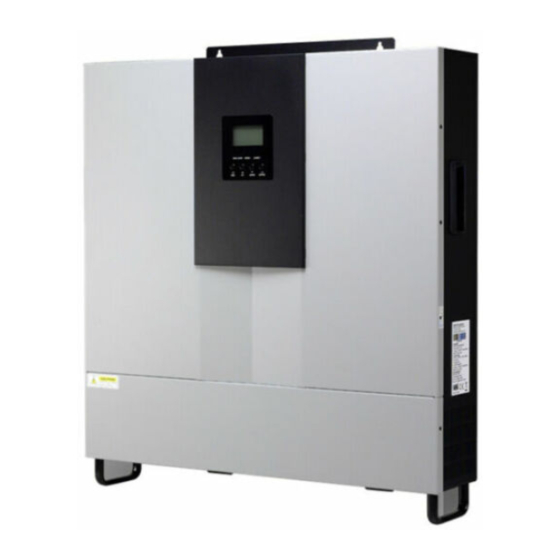
- Page 1 User Manual 3KW/5KW INVERTER / CHARGER Version: 1.3...
-
Page 2: Table Of Contents
Table Of Contents ABOUT THIS MANUAL ............................1 Purpose ................................1 Scope ................................1 SAFETY INSTRUCTIONS ........................... 1 INTRODUCTION ..............................2 Features ................................2 Basic System Architecture ..........................2 Product Overview ............................. 3 INSTALLATION ..............................4 Unpacking and Inspection..........................4 Preparation .............................. -
Page 3: About This Manual
ABOUT THIS MANUAL Purpose This manual describes the assembly, installation, operation and troubleshooting of this unit. Please read this manual carefully before installations and operations. Keep this manual for future reference. Scope This manual provides safety and installation guidelines as well as information on tools and wiring. SAFETY INSTRUCTIONS WARNING: This chapter contains important safety and operating instructions. -
Page 4: Introduction
INTRODUCTION This is a multi-function inverter/charger, combining functions of inverter, MPPT solar charger and battery charger to offer uninterruptible power support with portable size. Its comprehensive LCD display offers user-configurable and easy-accessible button operation such as battery charging current, AC/solar charger priority, and acceptable input voltage based on different applications. -
Page 5: Product Overview
Product Overview 1. LCD display 2. Status indicator 3. Charging indicator 4. Fault indicator 5. Function buttons 6. Power on/off switch 7. AC input 8. AC output 9. PV input 10. Battery input 11. Circuit breaker 12. Remote LCD panel communication port 13. -
Page 6: Installation
INSTALLATION Unpacking and Inspection Before installation, please inspect the unit. Be sure that nothing inside the package is damaged. You should have received the following items inside of package: The unit x 1 User manual x 1 Communication cable x 1 ... -
Page 7: Battery Connection
Install the unit by screwing three screws. It’s recommended to use M4 or M5 screws. Battery Connection CAUTION: For safety operation and regulation compliance, it’s requested to install a separate DC over-current protector or disconnect device between battery and inverter. It may not be requested to have a disconnect device in some applications, however, it’s still requested to have over-current protection installed. -
Page 8: Ac Input/Output Connection
WARNING: Shock Hazard Installation must be performed with care due to high battery voltage in series. CAUTION!! Do not place anything between the flat part of the inverter terminal and the ring terminal. Otherwise, overheating may occur. CAUTION!! Do not apply anti-oxidant substance on the terminals before terminals are connected tightly. -
Page 9: Pv Connection
WARNING: Be sure that AC power source is disconnected before attempting to hardwire it to the unit. 4. Then, insert AC output wires according to polarities indicated on terminal block and tighten terminal screws. Be sure to connect PE protective conductor ( ) first. -
Page 10: Final Assembly
PV Module Selection: When selecting proper PV modules, please be sure to consider below parameters: 1. Open circuit Voltage (Voc) of PV modules not exceeds max. PV array open circuit voltage of inverter. 2. Open circuit Voltage (Voc) of PV modules should be higher than min. battery voltage. Solar Charging Mode INVERTER MODEL 145Vdc... -
Page 11: Remote Display Panel Installation
Remote Display Panel Installation The LCD panel can be removable and installed in a remote site with an optional communication cable. Please follow below steps to implement this remote panel installation. Step 1. Loosen the screw on the two sides of bottom case and push up the case cover. Then, remove screw on the top of the display panel. -
Page 12: Dry Contact Signal
follow on-screen instruction to install the monitoring software. For the detailed software operation, please check user manual of software inside of CD. Bluetooth Connection This series is built in Bluetooth technology. You may simply go to google play to install “WatchPower”. It allows wireless communication up to 6~7m in an open space. -
Page 13: Operation
OPERATION Power ON/OFF Once the unit has been properly installed and the batteries are connected well, simply press On/Off switch (located on the button of the case) to turn on the unit. Operation and Display Panel The operation and display panel, shown in below chart, is on the front panel of the inverter. It includes three indicators, four function keys and a LCD display, indicating the operating status and input/output power information. -
Page 14: Lcd Display Icons
Function Keys Function Key Description Exit setting mode USB function setting Select USB OTG functions To last selection Down To next selection Enter To confirm the selection in setting mode or enter setting mode LCD Display Icons Icon Function description Input Source Information Indicates the AC input. - Page 15 Voltage mode Bottom three bars will be on and the top bar > 2.167 V/cell will flash. Floating mode. Batteries are fully charged. 4 bars will be on. In battery mode, it will present battery capacity. Load Percentage Battery Voltage LCD Display <...
-
Page 16: Lcd Setting
LCD Setting ” After pressing and holding “ button for 3 seconds, the unit will enter setting mode. Press “ ” or “ ” button to select setting programs. And then, press “ ” button to confirm the selection or “ ”... - Page 17 60A (default) 3KW model setting range is from Maximum charging current: 10A to 120A and increment of To configure total charging each click is 10A. current for solar and utility 5KW model setting range is from chargers. 10A to 140A and increment of (Max.
- Page 18 Automatically (default) If selected and utility is available, inverter will work in line mode. Once utility frequency unstable, inverter will work in bypass mode if bypass function is not forbidden in program 23. Online mode If selected, inverter will work in line mode when...
- Page 19 3KW model setting range is from 22.0V to 28.5V and increment of each click is 0.5V. 5KW model setting range is from 44.0V to 57.0V and increment of each click is 1.0V. 3KW model: The setting range is from 24.0V to 32.0V and increment of each click is 0.5V.
- Page 20 SLb: Solar energy for load Solar energy provides power to the first load first and disallow the utility to UdC: Disallow utility to charge battery. charge battery Alarm on (default) Alarm off Alarm control Return to default display If selected, no matter how users screen (default) switch display screen, it will automatically return to default...
- Page 21 Bypass disable If selected and power ON button is pressed on, inverter can work in bypass/ECO mode only if utility is available. Bypass function: Bypass enable (default) If selected and no matter power ON button is pressed on or not, inverter can work in bypass mode if utility is available.
- Page 22 L1 phase When the units are operated in 3-phase application, please choose “3PX” to define each inverter. It is required to have at least 3 inverters or maximum 9 inverters to support three-phase equipment. It’s required to have at least one inverter in each phase or it’s up to four L2 phase inverters in one phase.
- Page 23 Battery equalization enable Battery equalization disable (default) Battery equalization If “Flooded” or “User-Defined” is selected in program 05, this program can be set up. 3KW default setting: 29.2V 5KW default setting: 58.4V Battery equalization voltage Setting range is from 24.0V to 32.0V for 3KW model and 48.0V to 64.0V for 5KW model.
- Page 24 Reset Not reset(Default) Reset all stored data for PV generated power and output load energy Not reset(Default) Reset Erase all data log 3 minutes 5 minutes 10 minutes(default) 20 minutes Data log recorded interval *The maximum data log number is 1440. If it’s over 1440, it will re-write the first log.
- Page 25 For year setting, the range is from 17 to 99. Time setting – Year USB Function Setting Please insert USB disk into USB port ( ). Press and hold “ ” button for 3 seconds to enter USB function setting mode. These functions include to upgrade inverter firmware, export data log and re-write internal parameters from USB disk.
-
Page 26: Display Setting
If no button is pressed for 1 minute, it will automatically return to main screen. Error message for USB On-the-Go functions: Error Code Messages No USB disk is detected. USB disk is protected from copy. Document inside the USB disk with wrong format. If any error occurs, error code will only show 5 seconds. - Page 27 PV power = 500W PV power AC and PV charging current=50A PV charging current=50A Charging current AC charging current=50A AC and PV charging power=500W PV charging power=500W Charging power AC charging power=500W Battery voltage=25.5V, output voltage=230V Battery voltage and output voltage...
- Page 28 Output frequency=50Hz Output frequency Load percent=70% Load percentage When connected load is lower than 1kVA, load in VA will present xxxVA like below chart. Load in VA When load is larger than 1kVA (≧1KVA), load in VA will present x.xkVA like below chart. When load is lower than 1kW, load in W will present xxxW like below chart.
- Page 29 PV energy generated Today = 3.88kWh, Load output energy Today = 9.88kWh. PV energy generated today and Load output energy today PV energy generated this month = 388kWh, Load output energy this month = 988kWh. PV energy generated this month and Load output energy this month.
- Page 30 Main CPU version 00014.04. Main CPU version checking. Secondary CPU version 00003.03. Secondary CPU version checking. Bluetooth version 00003.03. Bluetooth version checking. SCC version 00003.03. SCC version checking...
-
Page 31: Operating Mode Description
Operating Mode Description Operation mode Description LCD display Charging by utility and PV energy. Charging by utility. Standby mode Note: No output is supplied by the *Standby mode: The inverter unit but it still can charge is not turned on yet but at this batteries. - Page 32 Charging by utility The unit will provide output power from the utility. PV Bypass/ECO Mode energy and utility can charge No charging batteries. *ECO mode disabled when in parallel mode. Charging by utility and PV energy. The unit will provide output power from the mains.
-
Page 33: Fault Reference Code
Fault Reference Code Fault Code Fault Event Icon on Fan is locked when inverter is off. Over temperature Battery voltage is too high Battery voltage is too low Output short circuited or over temperature is detected by internal converter components. Output voltage is too high. -
Page 34: Battery Equalization
Battery Equalization Equalization function is added into charge controller. It reverses the buildup of negative chemical effects like stratification, a condition where acid concentration is greater at the bottom of the battery than at the top. Equalization also helps to remove sulfate crystals that might have built up on the plates. If left unchecked, this condition, called sulfation, will reduce the overall capacity of the battery. - Page 35 However, in Equalize stage, when battery equalized time is expired and battery voltage doesn’t rise to battery equalization voltage point, the charge controller will extend the battery equalized time until battery voltage achieves battery equalization voltage. If battery voltage is still lower than battery equalization voltage when battery equalized timeout setting is over, the charge controller will stop equalization and return to float stage.
-
Page 36: Specifications
SPECIFICATIONS Table 1 Line Mode Specifications INVERTER MODEL Input Voltage Waveform Sinusoidal Nominal Input Voltage 230Vac Low Loss Voltage 110Vac± 7V Low Loss Return Voltage 120Vac± 7V High Loss Voltage 280Vac± 7V High Loss Return Voltage 270Vac± 7V Max AC Input Voltage 300Vac Nominal Input Frequency 50Hz / 60Hz (Auto detection) - Page 37 Table 2 Battery Mode Specifications INVERTER MODEL 3KVA/3KW 5KVA/5KW Rated Output Power Pure Sine Wave Output Voltage Waveform 230Vac± 5% Output Voltage Regulation 50Hz or 60Hz Output Frequency Peak Efficiency Overload Protection 5s@≥150% load; 10s@105%~150% load 2* rated power for 5 seconds Surge Capacity Nominal DC Input Voltage 24Vdc...
- Page 38 Table 3 Charge Mode Specifications Utility Charging Mode INVERTER MODEL Charging Current Default: 30A, max: 60A @ Nominal Input Voltage Flooded 29.2Vdc 58.4Vdc Bulk Battery Charging AGM / Gel Voltage 28.2Vdc 56.4Vdc Battery Floating Charging Voltage 27Vdc 54Vdc Overcharge Protection 34Vdc 66Vdc Charging Algorithm...
- Page 39 Table 4 ECO/Bypass Mode Specifications Bypass Mode INVERTER MODEL Input Voltage Waveform Sinusoidal Low Loss Voltage 176Vac± 7V Low Loss Return Voltage 186Vac± 7V High Loss Voltage 280Vac± 7V High Loss Return Voltage 270Vac± 7V Nominal Input Frequency 50Hz / 60Hz (Auto detection) Low Loss Frequency 46(56)±...
-
Page 40: Trouble Shooting
TROUBLE SHOOTING Problem LCD/LED/Buzzer Explanation / Possible cause What to do Unit shuts down LCD/LEDs and buzzer automatically will be active for 3 The battery voltage is too low 1. Re-charge battery. during startup seconds and then (<1.91V/Cell) 2. Replace battery. process. -
Page 41: Parallel Function
PARALLEL FUNCTION 1. Introduction This inverter can be used in parallel for two applications. 1. Parallel operation in single phase with up to 9 units. The supported maximum output power is 45KW/45KVA. 2. Maximum 9 units work together to support three-phase equipment. Seven units support one phase maximum. - Page 42 Step 4: Install new parallel board with 2 screws tightly. Step 5: Re-connect 2-pin and 14-pin to original position on parallel board as shown below chart. Step 6: Put wire cover back to the unit. Now the inverter is providing parallel operation function. 4.
- Page 43 5. Wiring Connection The cable size of each inverter is shown as below: Recommended battery cable and terminal size for each inverter: Ring terminal: Ring Terminal Torque Cable Dimensions Model Wire Size value D (mm) L (mm) 1*1/0AWG 49.7 2~ 3 Nm 49.7 2*4AWG 49.7...
- Page 44 Recommended battery capacity Inverter parallel numbers Battery Capacity 800AH 1200AH 1600AH 2000AH 2400AH 2800AH 3200AH 3600AH WARNING! Be sure that all inverters will share the same battery bank. Otherwise, the inverters will transfer to fault mode. 5-1. Parallel Operation in Single phase Two inverters in parallel: Power Connection Load...
- Page 45 Communication Connection Four inverters in parallel: Power Connection Load Communication Connection Five inverters in parallel: Power Connection Load...
- Page 46 Communication Connection Six inverters in parallel: Power Connection Load Communication Connection Seven inverters in parallel: Power Connection Load Communication Connection ① ② ③ ④ ⑤ ⑥ ⑦...
- Page 47 Eight inverters in parallel: Power Connection Load Communication Connection ① ② ③ ④ ⑤ ⑥ ⑦ ⑧ Nine inverters in parallel: Power Connection Load Communication Connection ① ② ③ ④ ⑤ ⑥ ⑦ ⑧ ⑨ 5-2. Support 3-phase equipment Three inverters in each phase: Power Connection Load...
- Page 48 Communication Connection ① ② ③ ④ ⑤ ⑥ ⑦ ⑧ ⑨ WARNING: Do not connect the current sharing cable between the inverters which are in different phases. Otherwise, it may damage the inverters. Two inverters in each phase: Power Connection Load Communication Connection...
- Page 49 Seven inverters in one phase and one inverter for the other two phases: Power Connection Load Note: It’s up to customer’s demand to pick 7 inverters on any phase. P1: L1-phase, P2: L2-phase, P3: L3-phase. Communication Connection ① ② ③ ⑤...
- Page 50 Communication Connection Three inverters in one phase, two inverters in second phase and one inverter for the third phase: Power Connection Load Communication Connection Three inverters in one phase and only one inverter for the remaining two phases: Power Connection Load...
- Page 51 Communication Connection Two inverters in two phases and only one inverter for the remaining phase: Power Connection Load Communication Connection Two inverters in one phase and only one inverter for the remaining phases: Power Connection Load...
- Page 52 Communication Connection One inverter in each phase: Power Connection Load Communication Connection WARNING: Do not connect the current sharing cable between the inverters which are in different phases. Otherwise, it may damage the inverters. 6. PV Connection Please refer to user manual of single unit for PV Connection. CAUTION: Each inverter should connect to PV modules separately.
- Page 53 7. LCD Setting and Display Setting Program: Program Description Selectable option Single When the unit is operated alone, please select “SIG” in program 28. When the units are used in parallel for single Parallel phase application, please select “PAL” in program 28.
- Page 54 8. Commissioning Parallel in single phase Step 1: Check the following requirements before commissioning: Correct wire connection Ensure all breakers in Line wires of load side are open and each Neutral wires of each unit are connected together. Step 2: Turn on each unit and set “PAL”...
- Page 55 Step 5: If there is no more fault alarm, the system to support 3-phase equipment is completely installed. Step 6: Please switch on all breakers of Line wires in load side. This system will start to provide power to the load.
-
Page 56: Appendix I: Approximate Back-Up Time Table
Appendix A: Approximate Back-up Time Table Model Load (VA) Backup Time @24Vdc 200Ah (min) Backup Time @24Vdc 400Ah (min) 2200 1050 1200 1500 1800 2100 2400 2700 3000 Model Load (VA) Backup Time @ 48Vdc 200Ah (min) Backup Time @ 48Vdc 400Ah (min) 1226 2576 1000... - Page 57 Appendix B: BMS Communication Installation 1. Introduction If connecting to lithium battery, it is recommended to purchase a custom-made RJ45 communication cable. Please check with your dealer or integrator for details. This custom-made RJ45 communication cable delivers information and signal between lithium battery and the inverter.
- Page 58 3. Installation and Operation After configuration, please install LCD panel with inverter and Lithium battery with the following steps. Step 1. Use custom-made RJ45 cable to connect inverter and Lithium battery. Step 2. Switch on Lithium battery. Step 3. Press more than three seconds to start Lithium battery, power output ready. Step 4.
- Page 59 4. LCD Display Information Press “UP” or “DOWN” key to switch LCD display information. It will show battery pack and battery group number before “Main CPU version checking” as below screen. Selectable information LCD display Battery pack numbers & Battery Battery pack numbers = 3, battery group numbers = 1 group numbers 5.
Need help?
Do you have a question about the LV5048 and is the answer not in the manual?
Questions and answers