Table of Contents
Advertisement
Quick Links
Advertisement
Table of Contents

Related Manuals for MPP Solar Grid PV-Inverter 10Kw


Summary of Contents for MPP Solar Grid PV-Inverter 10Kw
- Page 1 Grid PV-Inverter 10Kw Installation and Operation Manual Version 3.0E...
-
Page 2: Table Of Contents
Content READ THIS USER MANUAL BEFORE YOU START ....... 4 1. SAFETY INSTRUCTIONS ............. 5 2. LIMITED WARRANTY ..............7 3. OVERVIEW ..................8 3.1 I PV S ..................... 8 NTRODUCING THE YSTEM 3.2 I ....................8 NTRODUCING NVERTER 10KW PV 3.2.1 Dimensions of 10KW PV Inverter .................. - Page 3 12. DISPOSAL ................. 51 13. CONTACT INFORMATION ......14. COMPLIANCE OF STANDARDS ..........52 15. LOAD GRAPH AND EFFICIENCY GRAPH ......53 APPENDIX I: LINE LOSSES OF THE INVERTER ......54 APPENDIX II: SELECTING THE LINE CIRCUIT BREAKERS ..55...
-
Page 4: Read This User Manual Before You Start
Read this User Manual before you start Congratulations on purchasing Grid PV-Inverter (referred to in this 10KW manual as “PV-Inverter”, or simply “Inverter”). This PV-Inverter is a highly reliable product due to its innovative design and excellent quality control. The device is dedicated to high demand, 3 phase grid-linked PV systems. -
Page 5: Safety Instructions
1. Safety Instructions Risk of Electric Shock: Alternating Current (AC) and Direct Current (DC) sources are terminated in this device. To prevent risk of electric shock during maintenance or installation please ensure that all AC and DC terminals are disconnected. Be sure to secure the Ground line to the Grid’s Ground, and double check the Line and Neutral are not confused with Ground. - Page 6 PV-panel is exposed to sufficient radiation and connected to the device, it generates a DC voltage to charge the DC link capacitors. After disconnecting the PV-Inverter from the power supply and PV-panel, electrical charge can still reside in the DC link capacitors. Before handling the device, please allow at least 8 minutes after the power is disconnected.
-
Page 7: Limited Warranty
2. Limited Warranty PV-Inverter comes with a 5-year warranty. An optional extended 10kw Grid warranty may be available by special request before delivery. This warranty covers all defects due to design, manufacturing and components. This warranty does not cover damages resulting from: ... -
Page 8: Overview
3. Overview 3.1 Introducing the Grid PV System The Grid PV System is mainly composed of 5 parts: PV-panels, the PV-Inverter, DC-Connection Unit, AC-Connection Unit (connection Interface) and a connection to the Public Utility. When PV-panel is exposed to sufficient irradiation and connected to an inverter, it generates DC power. -
Page 9: Dimensions Of 10Kw Pv Inverter
3.2.1 Dimensions of 10KW PV Inverter The dimension is in millimeters. -
Page 10: Identification
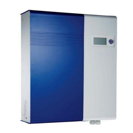
3.2.2 Identification On the left side of shows the type plate of the inverter. The type 10KW PV plate shows the Type, Specifications, and the Serial Number of the inverter. When encounter any difficulties during installation or operation, please record the Serial Number (SN) before contacting your local dealer or representative. - Page 11 3.2.3 Specific Parts of 10KW PV Inverter The descriptions of the major parts of 10KW PV Inverter are indicated below: (1) 3 Pairs of DC-Input Terminals: Each input pair consists of positive and negative terminals. Refer to Installation Section for set-up information. (2) Cooling Fan: The inverter is equipped with 3 air cooling fans to eject heat dissipated by the heat sink.
-
Page 12: Introducing Graphic Data Logger
3.3 Introducing Graphic Data Logger To show the information of inverter, there is a graphic Data Logger in the unit. This Data Logger can show various information of the inverter such as operational status and warning message. In addition, it can be removed from its slot to a place user prefers. -
Page 13: Configuration
3.3.1 Configuration The following table indicates the main specification of the Data Logger: Monochrome Each I/P power, O/P power, Operation mode and warning Displayed message Information 3 years Storage Period SD card Storage Media Via mini USB Data Download 3.3.2 Features Removable Data Logger The Data Logger is removable from its inverter. -
Page 14: Appearance
3.3.4 Appearance LCD: 128 x 64 graphic, monochrome Navigation Pad: “↑”, “↓”, “→” , “←” and “OK” in the center. Back light: 3 colors Pac:0W Pac:0W Pac:0W TEMPERATURE:42.8℃ TEMPERATURE:42.8℃ TEMPERATURE:42.8℃ Iac:0.0/0.0/0.0A Iac:0.0/0.0/0.0A Iac:0.0/0.0/0.0A Vac:219.4/219.3/219.3V Vac:0.0/0.0/0.0V Vac:219.4/219.3/219.3V STATUS:Normal STATUS:Fault STATUS:Normal No Utility... -
Page 15: Features
4. Features Lead-free, RoHS compliant High conversion efficiency 3 MPP (Maximum Power Point) trackers IP65 enclosure 128x64 graphic display 3-phase 4 wire, 400V Compact design High reliability Easy operation Maintenance free ... -
Page 16: Installation
5. Installation 5.1. Inside the Package The following items are included in the Package: (1) PV-Inverter x 1 (2) Installation and Operation Manual x 1 (3) Mounting Screws(M4) x 4 and Snap Bushings x 4 (4) Safety-lock screws x 2 (5) Mounting Bracket for the inverter x 1 (6) Service Card x 1 (7) Mounting plate of the data logger x 1... - Page 17 To mount the inverter to a wall, please follow the steps: (1) It is recommended to choose a dry place, out of direct sunlight with ambient temperature between 0 and 40°C (2) Select a wall or solid vertical surface which is strong enough to support the inverter.
- Page 18 (4) Fix the Bracket by using Outer Mounting Holes: (a) To install the device to a wall, mark 4 outer holes with φ6.35mm at the back of the bracket as illustrated below. (b) Drill the 4 marked holes in the wall, and then drive in the 4 Snap Bushings(φ...
- Page 19 (5) Fix the Bracket by Using Central Mounting Holes: (a) To install the device to a narrow upright, mark 3 central holes at the back of the bracket as illustrated below. (b) Drill the 3 marked holes in the wall, and then drive in the 3 Snap Bushings.
- Page 20 (7) Insert the Safety Lock screws to fix the PV-Inverter in place. (8) Ensure the device is properly fixed to the bracket.
- Page 21 (9) Users can install Data Logger separately from the main unit. The mounting plate of the data logger and 2 screws are included in the accessories package (a) Fix the mounting plate of the data logger by 2 screws. Note: Screw (M4) size is φ 4mm x L 33.2mm. (b) Drill 2 holes in the wall, insert the screws, and tighten to fix the Data Logger in place.
-
Page 22: Connecting The Ac-Output Cable
5.3. Connecting the AC-Output Cable Connect PV-Inverter to the AC-Junction box via the AC-output cable and Ground cable as shown in the following steps: Find the recommended AC-output cable size: Do not use cables where losses will exceed 1%, see Appendix 1 L1 (phase R), L2 (phase S), L3 (phase T), N (Neutral), Gnd (PE): 4/6mm Gnd (PE): 10mm... - Page 23 Insert the AC-output cables correspondingly. The Brown wire (phase R) to L1, the Black wire (phase S) to L2, the Grey wire (phase T) to L3, the Blue wire to N (Neutral), and the Yellow-Green wire to Gnd (PE) of the terminal block. Fix the L1 (R), L2 (S), L3 (T), N (Neutral), and Gnd (PE) .
- Page 24 Fix the AC output cover back with a screwdriver. Twist on the connector cable gland to lock the bushing and cable.
-
Page 25: Connecting Pv-Panel
5.4. Connecting PV-Panel For connecting DC input, connected strings must consist of modules of the same type. The number, orientation, and tilt of panels may differ for different application usage. The following are the specification of the plug connectors. Connector Type Cable connection dimension Max. - Page 26 Attention: Before connecting DC power to Inverter, please check with multimeter to make sure that the polarity of each DC input pairs are correct. As shown below. (3) Each set of PV-Inverter DC terminal converts maximum DC input current of 13A. As a result, 3 pairs of PV-Inverter DC terminals can take a combined input current of up to 39A.
-
Page 27: Connecting To The Junction Box
5.5. Connecting to the Junction box The AC Junction box is an interface between PV-Inverter and the Public Utility. It may consist of an electrical breaker, fuse, surge protector and terminals for connection to both the PV-Inverter and the Public Utility. This AC Junction box must be designed by a qualified technician to comply with local safety standards requirement. -
Page 28: Post Installation Checklist
5.6 Post Installation Checklist (1) High voltages exist when PV-Panel is exposed to sufficient irradiation. Exposed terminals of PV-Panel are under tension, and can cause electric shock. Avoid making physical contact with those parts of the device. (2) After PV-Panels are connected to the PV-Inverter, the output voltage is greater than 300V and when the AC grid is not connected to the inverter, the Data Logger LCD displays the following:... -
Page 29: Operation Of 10Kw
6. Operation of 10KW PV Inverter 6.1 Auto Power-up The PV-Inverter starts up automatically once the DC-power from PV Panel is sufficient and fuse is closed. 6.2 Operating Modes There are 4 modes of operation. For each mode, there is a corresponding color and text to indicate the status. - Page 30 (3)During Fault During grid fault or system failure (refer to “error message table” for further information) the inverter disconnects from the grid, the backlight turns red, and alarm is ON to notify user. User can press “OK” button on navigation pad to clear fault notification.
-
Page 31: Using The Lcd Display And Data Logger
6.3 Using the LCD Display and Data Logger 6.3.1 Operation (1)Keys on the data logger: On the data logger, there are 5 keys used to change and operate. Generally, the functions of keys are defined as followings. “→”: View the lower layer (1 to 2 ) or move the cursor right ... -
Page 32: Display On Lcd
6.3.2 Display on LCD (1)Startup After the inverter starts up, the LCD shows logo and firmware version. The frame lasts for 3 seconds and changes to text information. (2)Text display The display shows four measurements and one status. The bottom-right part of the display shows the time and date. - Page 33 (3)Daily graph By pressing the “↓” key in the text display, screen on LCD is transformed to daily graph as below. The graph indicates the AC power trend of a specified date. Further explanations are stated below: Time-axis (x-axis): On the frame, the longest period is 12 hours. The number represents the hour.
- Page 34 (5)Error history By pressing “↓” again on the “Weekly Display”, the LCD changes to “Error Message” as shown below. The LCD displays the last two recorded error events. To see more error events, press “OK” first to toggle the display and then press “→” and “←”. ERROR HISTORY E073:Grid fault @ 02/12/09 2:44...
-
Page 35: Data Logger Function Tree
6.3.3 Data Logger Function Tree: The following is the summary of the operation: Function tree Initial screen 1st layer 2nd layer 1. Select channel by up-down arrow Left-Right 2. Press enter to change After 5 second arrow Channel Welcome Text display 3. - Page 36 6.4 Display Messages Operating conditions In English In German Description Normal Working Status In case of input voltage < 200V, PV Power off No display Keine Anzeige inverter is totally shutdown Input voltage range: Standby Status:Standby Status:Standby 200V~ 260V Initialization & waiting Status:Waiting Status:Warten Input voltage range: 260~350V...
- Page 37 Operating conditions In English In German Description Internal Temperature Temperature:xx.xºC Temperatur:xx.xºC Temperature is indicated in Celsius System Fault Earth fault of PV-panels or failure of Isolation failure Isolation Fault Isolationsfehler surge voltage protection Leakage current on ground conductor GFCI active Ground I Fault Fehlerstrom is too high...
- Page 38 Operating conditions In English In German Description The Master and Slave CPU F/W Firmware version Version:xx.xx-xx.xx Version:xx.xx-xx.xx version information Memory utilization percentage on SD SD card memory Memory:xx.x% Speicher:xx.x% card Datum:DD/MM/YY Date display Date:DD/MM/YY Sun Date display Son. Datum:DD/MM/YY Date display Date:DD/MM/YY Mon Date display Mon.
- Page 39 Operating conditions In English In German Description Weekly graph No Weekly Records Keine Wochenaufz. No data for weekly graph display Error history Error History Fehler banner Error history No Error History Keine Fehler No data for error history display Error history Value=N/A Value= N/A fault value is not available...
-
Page 40: Communication Interface
7. Communication Interface 7.1. RS-232 (on inverter) The PV-Inverter is equipped with a versatile communications interface. Use the inverter “Pro Control” to monitor the status of multiple inverters. Firmware upgrades are also available via this interface. The inverter is integrated with a DB9 socket for the RS-232 interface. Open the DB9 socket cover before use. -
Page 41: Downloading Data Inside Data Logger
8. Downloading Data inside Data Logger To manage the data inside the Data Logger, please take out the Data Logger from inverter and access its internal data via USB cable. The Data Logger is powered directly by the PC’s USB port. 8.1. -
Page 42: How To Access And Manage Log Data
8.2. How to Access and Manage Log Data Remove the Data Logger from the inverter and disconnect the RS-232 (1) cable. Unscrew and take off the cover of mini-B USB port. For PC with Windows ME, 2000, and XP, Vista, Windows 7, it is not necessary to install driver to access the data logger. - Page 43 (4)Copy the “DAILY” folder in the “Removable Disk” and paste it on the “Desktop.” (5)Execute the Pro-Control program. Then, click “File”, select “Export/Import”. (6)Select “Date from” and “Date to” the period which you prefer. Then, click “Import” button.
- Page 44 (7)Select “DAILY.dat” file under your previous saved DAILY folder. Then, click “Open” button. (8)Click “View” button and the log data will be processed by Pro-Control software in few seconds. (9)Click “Export” button...
- Page 45 (10)Click “Save” button. Then, log data will be saved in .CSV format in your preferred directory in your PC (11) Click “OK” button. (12)Double click “DAILY.CSV” file in your preferred directory in your PC. After that, you can manipulate the log data with Microsoft Excel.
-
Page 46: Troubleshooting
9. Troubleshooting PV-Inverter requires very little maintenance. When unexpected situation occurs, please refer to the following table for quick troubleshooting before contacting your local service. The following table lists common fault messages and ways to cope with the fault or error. Fault Analysis and Actions Fault Proposed Actions for... - Page 47 Fault Proposed Actions for Proposed Actions for Fault definition Possible Causes Message End-user Professionals The detected 1. The PV array Open DC connection 1. Check the open PV PV voltage is voltage is too high of inverter and voltage, and see if it is higher than 2.
- Page 48 Fault Proposed Actions for Proposed Actions for Fault definition Possible Causes Message End-user Professionals DC BUS voltage Inverter is abnormal Disconnect PV (+) 1. Do the same actions as inside inverter is and PV (-) from the left column again lower than input, start the unit 2.
-
Page 49: Preventative Maintenance
10. Preventative maintenance Although PV-Inverter requires very little maintenance, the following inspections at regularly would help to ensure PV Inverter operation with optimal performance. 10.1 Visual Inspection Check the inverter and cables for any signs of external damage. Contact your installer immediately if you find any defects. -
Page 50: Specifications
11. Specifications Model 10KW Germany Market Nominal AC output power 10000 W Max. AC output power in 10 minutes 11000 W Input Nominal DC voltage 640 V Maximum PV power / Tracker 5500 W Maximum PV open voltage 800 V Full load rated voltage range 400 ~ 720V MPPT voltage range... -
Page 51: Disposal
12. Disposal The dealer or installers should remove the PV Inverter from the array and contact the supplier for disposal instructions The inverter must not be disposed of with the household waste. Dispose of the PV Inverter at the end of its service life should be done in accordance with the disposal regulations for electronic waste which apply at the installation site at that time. -
Page 52: Compliance Of Standards
14. Compliance of Standards EMC: DIN EN 61000-6-3 (class B) DIN EN 61000-6-2 Grid Interface Regulation: VDE0126-1-1 (2006) Safety: DIN EN 50178 LVD: 2006/95/EC EMC: 2004/108/EC Environment Category: Pollution Degree II Overvoltage Category III *Note: Both DC input and AC output of the inverter have equipped with surge protection component which is VDE IEC61051-1 recognized. -
Page 53: Load Graph And Efficiency Graph
15. Load Graph and Efficiency Graph The relationship between PV input voltage (String voltage, V ) and input power (P ) is shown in the following example. Once the PV input voltage is less than 423V, the relation of V and power is: (W) = 0.0205 x V + 4.8 x V... -
Page 54: Appendix I: Line Losses Of The Inverter
Appendix I: Line losses of the Inverter The following maximum cable lengths are possible for the different cable cross-sections: Cable cross-section 0 mm2 0 mm2 34 m 51 m Max. cable length... -
Page 55: Appendix Ii: Selecting The Line Circuit Breakers
Appendix II: SELECTING THE LINE CIRCUIT BREAKERS the maximum possible nominal current for the cable used and the maximum possible fuse protection for the inverter limit the maximum possible nominal current for the line circuit breaker additionally, check the thermal suitability of the line circuit breakers When selecting line circuit breakers, a number of load factors needs to be taken into account.
Need help?
Do you have a question about the Grid PV-Inverter 10Kw and is the answer not in the manual?
Questions and answers