Table of Contents
Advertisement
Advertisement
Table of Contents

Related Manuals for MPP Solar 3k hybrid


Summary of Contents for MPP Solar 3k hybrid
- Page 1 User Manual Hybrid PV Inverter Version: 2.1...
-
Page 2: Table Of Contents
Table Of Contents Introduction ..................1 Important Safety Warning ..............2 Unpacking & Overview ................4 3-1. Packing List ..................4 3-2. Product Overview ................4 Installation ..................5 4-1. Selecting Mounting Location ..............5 4-2. Mounting Unit..................5 5. Grid (Utility) Connection ................7 5-1. -
Page 3: Introduction
1. Introduction This hybrid PV inverter can provide power to connected loads by utilizing PV power, utility power and battery power. Hybrid inverter Distribution Box PV module Electric grids Load Battery Figure 1 Basic hybrid PV System Overview Depending on different power situations, this hybrid inverter is designed to generate continuous power from PV solar modules (solar panels), battery, and the utility. -
Page 4: Important Safety Warning
2. Important Safety Warning Before using the inverter, please read all instructions and cautionary markings on the unit and this manual. Store the manual where it can be accessed easily. This manual is for qualified personnel. The tasks described in this manual may be performed by qualified personnel only. - Page 5 CAUTION! Use only recommended accessories from installer . Otherwise, not-qualified tools may cause a risk of fire, electric shock, or injury to persons. CAUTION! To reduce risk of fire hazard, do not cover or obstruct the cooling fan. CAUTION! Do not operate the Inverter if it has received a sharp blow, been dropped, or otherwise damaged in any way.
-
Page 6: Unpacking & Overview
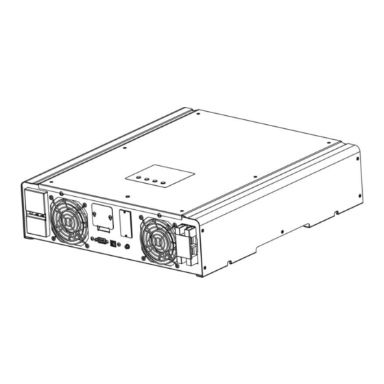
3. Unpacking & Overview 3-1. Packing List Before installation, please inspect the unit. Be sure that nothing inside the package is damaged. You should have received the following items inside of package: Inverter unit Software CD Manual USB cable 3-2. Product Overview PV connectors Grid connectors Battery connectors... -
Page 7: Installation
4. Installation 4-1. Selecting Mounting Location Consider the following points before selecting where to install: Do not mount the inverter on flammable construction materials. Mount on a solid surface This inverter can make noises during operation which may be perceived as a nuisance in ... - Page 8 1. Drill four holes in the marked locations Place the unit on the surface and align the with four screws. mounting holes with the four screws. 3. Check if the solar inverter is firmly Note: Recommended specs for screws. secured.
-
Page 9: Grid (Utility) Connection
5. Grid (Utility) Connection 5-1. Preparation Before connecting to AC utility, please install a separate AC circuit breaker between inverter and AC utility. This will ensure the inverter can be securely disconnected during maintenance and fully protected from over current of AC input. NOTE1: Although this inverter is equipped with 250VAC/30A fuse, it’s still necessary to install a separate circuit breaker for safety consideration. -
Page 10: Pv Module (Dc) Connection
Step 6: For safe operation, please use one more wire with ring terminal to connect grounding. Refer to Chart 3. Ring terminal: Chart 3 Recommended wire and terminal size: Ring Terminal Wire Size Dimensions Torque value Cable mm 2 D (mm) L (mm) 10 AWG 21.8... - Page 11 Step 1: Check the input voltage of PV array modules. The acceptable input voltage of the solar inverter is 250VDC - 450VDC for 3KW/3KW Plus and 150VDC-320VDC for 2KW. This system is only applied with one string of PV array. Please make sure that the maximum current load of PV input connector is 13A for 3KW, 18A for 3KW Plus and 15A for 2KW.
-
Page 12: Battery Connection
7. Battery Connection CAUTION: Before connecting to batteries, please install separately a DC circuit breaker between inverter and batteries. NOTE: Please only use sealed lead acid battery, vented and Gel battery. Please check maximum charging voltage and current when first using this inverter. If using Lithium iron or Nicd battery, please consult with installer for the details. -
Page 13: Load (Ac Output) Connection
8. Load (AC Output) Connection CAUTION: To prevent further supply to the load via the inverter during any mode of operation, an additional disconnection device should be placed on in the building wiring installation. WARNING! It's very important for system safety and efficient operation to use appropriate cable for AC connection. -
Page 14: Communication
9. Communication The inverter is equipped with RS232 and USB ports and it is also equipped with a slot for alternative communication interfaces in order to communicate with a PC with corresponding software. This intelligent slot is suitable to install with SNMP card and Modbus card. Follow below procedure to connect communication wiring and install the software. -
Page 15: Commissioning
10. Commissioning Step 1: Check the following requirements before commissioning: Ensure the inverter is firmly secured Check if the open circuit DC voltage of PV module meets requirement (Refer to Section Check if the open circuit utility voltage of the utility is at approximately same to the ... -
Page 16: Initial Setup
11. Initial Setup Before inverter operation, it’s required to set up “Operation Mode” via software. Please strictly follow below steps to set up. For more details, please check software manual. Step 1: After turning on the inverter and installing the software, please click “Open Monitor” to enter main screen of this software. - Page 17 SECTION A: Standard: It will list local grid standard. It’s requested to have factory password to make any modifications. Please check local dealer only when this standard change is requested. CAUTION: Wrong setting could cause the unit damage or not working. Nominal Output Voltage: There are 5 options for high voltage system to select, 240V, 230V, 220V, 208V and 202V.
- Page 18 Allow AC to charge battery: This option is automatically determined by setting in ”Charging source”. It’s not allowed to modify here. When “Grid and PV” or “Grid or PV” is selected in charging source section, this option is default selected. Under Grid-tie mode, this option is invalid.
- Page 19 PV energy supply priority setting: 1 Battery, 2 Load and 3 Grid. PV power will charge battery first, then provide power to the load. If there is any remaining power left, it will feed-in to the grid. Battery charging source: PV and Grid (Default) It’s allowed to charge battery from PV power first.
- Page 20 Grid-tie with backup (II) : PV energy supply priority setting: 1 Load, 2 Battery and 3 Grid. PV power will provide power to the load first. Then, it will charge battery. If there is any remaining power left, it will feed-in to the grid. Battery charging source: PV and Grid It’s allowed to charge battery from PV power first.
- Page 21 NOTE: This option will become ineffective during AC charging time and the priority will automatically become 1 Grid and 2 Battery order. Otherwise, it will cause battery damage. Grid-tie with backup (III): PV energy supply priority setting: 1 Load, 2 Grid and 3 Battery PV power will provide power to the load first.
- Page 22 When PV power is not available: Grid, 2 Battery: Grid will provide power to the load at first. If grid is not available, battery power will provide power backup. Battery, 2 Grid: Battery power will provide power to the load at first. If battery power is running out, grid will back up the load.
- Page 23 Working logic under off-peak time: PV energy supply priority: 1 Battery, 2 Load and 3 Grid PV power will charge battery first. If PV power is sufficient, it will provide power to the loads. The remaining PV power will feed to the grid. NOTE: The max.
- Page 24 Load supply source: When PV power is available: PV, 2 Battery, 3 Grid PV power will provide power to the load first. If it’s not sufficient, battery power will provide power to the load. When battery power is running out or not available, grid will back up the load.
- Page 25 Off-Grid Off-Grid (I): Default setting for off-grid mode. PV energy supply priority setting: 1 Load, 2 Battery PV power will provide power to the load first and then charge battery. Feed-in to the grid is not allowed under this mode. At the same time, the grid relay is connected in Inverter mode.
- Page 26 Grid, 2 Battery Grid will provide power to the load at first. If grid is not available, battery power will provide power backup. Battery, 2 Grid (Default) Battery power will provide power to the load at first. If battery power is running out, grid will back up the load.
- Page 27 PV power will provide power to the load first. If it’s not sufficient, grid will provide power to the load. If grid is not available at the same time, battery power will back up. When PV power is not available: Grid, 2 Battery: Grid will provide power to the load at first.
- Page 28 Load supply source: When PV power is available: 1 PV, 2 Battery, 3 Grid PV power will provide power to the load first. If it’s not sufficient, battery power will back up the load. Only after battery power is running out and stop providing the load, Grid will back up the load.
-
Page 29: Operation
12. Operation 12-1. Interface This display is operated by four buttons. NOTICE: To accurately monitor and calculate the energy generation, please calibrate the timer of this unit via software every one month. For the detailed calibration, please check the user manual of bundled software. 12-2. - Page 30 Indicates battery voltage or percentage. Volt: voltage, %: percentage Indicates charging current to battery. Indicates that the warning occurs. Indicates that the fault occurs. Indicates fault code or warning code. Indicates date and time, or the date and time users set for querying energy generation.
-
Page 31: Button Definition
12-3. Button Definition Button Operation Function Enter query menu. Short press. If it’s in query menu, press this button to confirm selection or entry. ENTER/ON Press and hold the button for This inverter is able to provide power to approximately 1 second when connected loads via AC output connector. - Page 32 Setting Display Procedure Input voltage or frequency of AC input Procedure Enter Enter Enter Down Down Frequency, voltage, power or percentage of AC output Procedure Enter Enter Enter Down Down...
- Page 33 Input voltage or power of PV input. Procedure Enter Enter Enter Down Down Battery voltage or percentage. Procedure Enter Down Enter Enter Down...
- Page 34 Date and time. Procedure Enter Down Enter Enter Down Today or total energy generated. Procedure Enter Down Enter Enter Down...
-
Page 35: Lcd Display
Mode of query energy generated. Energy generation display of selected day Procedure Enter Down Enter Up Down Sets year Flashes Enter Enter Enter Up Down Sets month Flashes Enter Returns to main menu Down Down Enter Up Down Sets day Flashes LCD Display: Energy generation display of selected month... -
Page 36: Operation Mode & Display
Energy generation display of selected year Procedure Enter Down Enter Down Enter Enter Up Down Sets year Flashes Enter Returns to main menu LCD Display: 12-5. Operation Mode & Display Below is only contained LCD display for grid-tie with backup mode (I). If you need to know other operation mode with LCD display, please check with installer. - Page 37 PV power is sufficient to charge the battery first. However, remaining PV power is not sufficient to back up the load. Therefore, remaining PV power and the utility are supplying power to the connected load. PV power is generated, but not sufficient enough to charge battery by itself.
- Page 38 PV power is sufficient to provide power to loadsand feed power back to utility. No battery is connected or battery is not available to use at this moment. icon is flashing. PV power and utility are providing power to the connected loads because of insufficient PV power.
- Page 39 PV power is not detected or available at this moment. Only battery power is available to provide power to connected loads. At the same time, the utility is out of range. icons are flahsing. Only PV power is available to provide power to connected loads.
- Page 40 Standby mode : The inverter is working without DC/INV operation and load connected. LCD Display Description The utility is out of range. This inverter is disabled on AC output or even AC power output is enabled, but an error occurs on AC output. Only PV power is sufficient to charge battery.
-
Page 41: Charging Management
13. Charging Management Default Charging voltage Note Value It can be adjusted via software from Max. charging current 5Amp to 25Amp. It can be adjusted via software from Floating charging voltage(default) 54.0 Vdc 50Vac to 58Vdc. Max. absorption charging It can be adjusted via software from 56.0 Vdc voltage(default) 50Vac to 58Vdc. - Page 42 If using sealed lead acid battery, please set up the max. charging current according to below formula: The maximum charging current = Battery capacity (Ah) x 0.2 For example, if you are using 125 Ah battery, then, maximum charging current is 125 x 0.2=25 (A).
-
Page 43: Applications With Energy Meter
14. Applications with Energy Meter With Modbus card II and energy meter, hybrid inverter can be easily integrated into the existing household system. For details please refer to Modbus card II manual. For single inverter application: Equipped with Modbus card II, hybrid inverter is connected to energy meter with RS485 communication port. -
Page 44: Maintenance & Cleaning
15. Maintenance & Cleaning Check the following points to ensure proper operation of whole solar system at regular intervals. Ensure all connectors of this inverter are cleaned all the time. Before cleaning this inverter, be sure to turn off all the breakers (AC breaker, battery ... -
Page 45: Trouble Shooting
16. Trouble Shooting When there is no information displayed in the LCD, please check if PV module connection is correctly connected. NOTE: The warning and fault information can be recorded by remote monitoring software. 16-1. Warning List When a warning situation occurs, icon will flash and the fault code area will display “WR”... -
Page 46: Fault Reference Codes
Warning Icon Description (flashing) Overload Overload Over temperature alarm Over temperature No electrical ground Ground loss 16-2. Fault Reference Codes When a fault occurs, the icon will flash as a reminder. See below for fault codes for reference. Situation Fault Icon Solution Fault Event... - Page 47 your installer. PV input voltage exceeds Check if the open circuit the upper threshold voltage of PV modules is higher than 500VDC. If PV open circuit voltage is less than 500VDC and the error message remains, pelase contact your installer. Auxiliary power* failed Turn off the inverter.
- Page 48 secondary controllers disconnect DC breaker. After LCD screen is Communication with the completely off, turn on DC main and secondary breaker. Until it shows “No controllers is interrupted Utility” in LCD display, turn Discharge circuit fault on AC breaker. After 300 Soft start in battery seconds, the system will discharge fails...
- Page 49 error, turn on the PV DC breaker and battery breaker. Turn on the inverter. If error message remains, please contact your installer. Fan fault Please check if fans are runing ok. If fans are runing ok, please shut down inverter first and then, restart it.
- Page 50 If mis-connected, re-connect it correctly. And turn on the inverter again. If error message still remains, please contact your installer.
-
Page 51: Specifications
17. Specifications MODEL 3KW Plus RATED POWER 2000 W 3000 W PV INPUT (DC) Maximum DC Power 2250 W 3200 W 4500 W Nominal DC Voltage 300 VDC 360 VDC Maximum DC Voltage 350 VDC 500 VDC Start-up Voltage / Initial Feeding Voltage 80 VDC / 120 VDC 116 VDC / 150 VDC MPP Voltage Range... - Page 52 GENERAL PHYSICAL Dimension, D X W X H (mm) 480 x 438 x 117 Net Weight (kgs) 15.57 INTERACE Communication Port RS-232/USB Optional SNMP, Modbus and AS-400 cards Intelligent Slot available ENVIRONMENT Protective Class Ingress Protection Rating IP20 Humidity 0 ~ 90% RH (No condensing) Operating Temperature 0 to 40°C Altitude...
Need help?
Do you have a question about the 3k hybrid and is the answer not in the manual?
Questions and answers