DAXOM Naviels UKDAX-10EDT Installation And Operating Manual
Electric boiler
Hide thumbs
Also See for Naviels UKDAX-10EDT:
- Installation and operating manual (22 pages) ,
- Installation and operating (47 pages)
Table of Contents
Advertisement
Dear DAXOM User
In order to perform device's function properly and for your safety follow the
instructions mentioned in the user manual of the device during the mounting
and the usage of the device.
In case of an unauthorized mounting and maintenance, the device will be void
from warranty cover. In addition to that, our company will not be responsible
from failure or an accident that may occur in the device.
Please keep this user manual in good conditions for future reference.
Advertisement
Table of Contents

Related Manuals for DAXOM Naviels UKDAX-10EDT


Summary of Contents for DAXOM Naviels UKDAX-10EDT
- Page 1 Dear DAXOM User In order to perform device’s function properly and for your safety follow the instructions mentioned in the user manual of the device during the mounting and the usage of the device. In case of an unauthorized mounting and maintenance, the device will be void from warranty cover.
-
Page 2: Safety Warnings
1. SAFETY WARNINGS 1. Device installation must be made by authorized personnel according to instructions that aredetermined inside this manual. 2. Start-up of device must be made by Authorized Service. Do not try to operate the device by yourself. 3. Connection of water and heating installation of the device must be made as safety. - Page 3 In case of water leakage happens, water feed must be close and authorized service agency must be immediately informed. Hydraulic system operation pressure must be between 1 and 2 bars therefore it must not exceed 3 bars. In case of need, pressure can be reset as shown under the paragraph “FILLING THE SYSTEM”.
- Page 4 3. Adjustable needed temperature value for every part by using thermostatic valve for radiators increases the saving but using of room thermostat and thermostatic valve at the same time can create problem. 4. While using of thermostatic valve and room thermostat,for sensing the temperature correctly, make suitable position of objects such as curtain and goods that influence ambient airstream.
-
Page 5: Configuration Of The Device
3. CONFIGURATION OF THE DEVICE... -
Page 6: Technical Specifications
4. TECHNICAL SPECIFICATIONS Technical Specifications Power (kW) Dimensions Weight (Kg) Expansion Δt=25 C Hot Water L*W*H (mm) Tank (l) Amount (l/min) Model 3~400 V.50 Hz Electrical Heating and Hot Water UKDAX-10EDT 700*400*250 UKDAX-12EDT 700*400*250 UKDAX-16EDT 700*400*250 UKDAX-18EDT 700*400*250 10,4 UKDAX-20EDT 700*400*250 11,5 UKDAX-24EDT... - Page 7 5. INSTALLATION OF BOILER Boiler installation must be done by authorized personnel.
- Page 8 5. 1 INSTALLATION CONDITIONS AND SAFETY WARNINGS Obey minimum distance that is anticipated for installation in order to reach the device for making regular maintenance.
- Page 9 For the right position of the device; Do not place on the cooker or similar cooking devices. Do not leave combustion products inside device installed room. Heating sensitive walls (for example wooden walls) must be protected with steady insulation. Before the installation, wash the all system pipes carefully for removing any residual things that can give damage to operation of the device.
- Page 10 needed, fitting constriction or blockage can cause inability circulation of heating. Connections that are made to device must be easy removable when it is needed. Valve and silt trap must be used for water and radiator inlet pipe 5.2.1.1 Filling Heating System for Models of EDT and EDM After hydraulic connections are made, filling the heating system is necessary.
- Page 11 5.2.1.2 Filling Heating System for Models of ETT and ETM After hydraulic connections are made, filling the heating system is necessary. For the model of UKDAX –xxET Tand UKDAX –xxEDM this process is made with filling valve connected to heating system. For this, connection with valve must be made from cold water installation to heating system.
-
Page 12: Electrical Connections
device is opened. Silt trap is needed after filling valve. Filling process must be done by implementing following instructions. Open filling tap until water pressure indicator comes between 1 and 1, 5 bar. Close the filling tap when filling is completed. ... - Page 13 3~400 V. 50 Hz Electrical Heating and Hot Water 3~400 V.50 Hz Electrical Only Heating UKDAX 5*2,5 UKDAX 5*2,5 3*15,2 3*16 3*15,2 3*16 10EDT 10ETT UKDAX 5*2,5 UKDAX 5*2,5 3*18,2 3*20 3*18,2 3*20 12EDT 12ETT UKDAX 5*2,5 UKDAX 5*2,5 3*24,3 3*25 3*24,3 3*25...
-
Page 14: Lcd Display
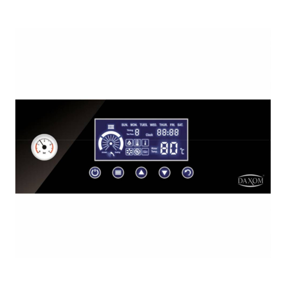
6. OPERATION AND USING OF THE DEVICE 6.1 LCD DISPLAY Operating Condition and settings of the device can be follow from LCD panel. Radiator operation indicator Days of week Time programming. Can be made 3 pcs time programming Hour Capacity indicator Ready to Operation indicator... - Page 15 Water heating indicator Radiator heating indicator Over Heating Indicator Over Heating Difference Value Pump operation indicator Freezing prevention indicator Room ThermostatConnection indicator Temperature indictor 6.2 FUNCTION KNOBS Use knobs located under LCD display for boiler using.
- Page 16 ON / OFF Menu Exit / changing Temperature increase / up Temperature decreasing /down Reset / Timer ON OFF 6.3 Operation of the Device First operation of the device must absolutely made by Authorized Service. Our company is not responsible from damages and accidents which can be occur associated with intervention to device by unauthorized people.
- Page 17 Be sure device water and radiator valves are open. (Only radiator valve is open for ETT and ETM models.) Be sure that fuse andresidual current deviceare positioned as preventing electric transition. After you open enough insulation from head of electrical cables, place whole conductive part of cable by loosening connection terminal occurred at device and tightens cable holder screw as not looseness.
-
Page 18: Day And Time Setting
6.4.2 RADIATOR HEATING SETTING OPERATION PARAMETER SETTINGS 6.4.1 DAY AND TIME SETTING 1. Bring the device “OFF” position. 2. Keep press button 5-6 seconds, days start to blink, day setting makes with buttons. 3. Press button,hour blinks time setting between 0 and 23is done by pressing orbuttons. - Page 19 radiator temperature set, “WATER TEMPERATURE “expression fizzle out and setting temperature starts to blinks. Two seconds later after setting is completed, device operation temperature is seen in LCD and “WATER TEMPERATURE” also seen in LCD. Reaching setting temperature of the device can take a time. 6.4.3 SETTING TAP WATER TEMPERATURE Bath water temperature can be made in 3 ways.
- Page 20 6.4.4 MAKING ΔT TEMPERATURE DIFFERENCE SETTING While the device reaches to overheat temperature mode, it can be set temperature difference which is wanted to operate. While the device is operating regularly, 1. Enter setting menu by pressing button 2-3 seconds. 2.
- Page 21 3. With buttons, it is set to “1” for room thermostat bring into use, it is set to “0” for putting hold on device. 4. Exit setting menu by pressing button. 6.4.6MAKING SETTING OF HEATING MODE Device can be set according to floor heating (low temperature) and radiator heating system.
- Page 22 6.4.7MAKING SETTING OF THE CAPACITY Device can operate with 3 different capacities. P1 mean is 1/3 capacity, P2 mean is 2/3 capacity, P3 mean is full capacity. For example, if the device is 24Kw, P1: 8Kw, P2: 16Kw, P3:24Kw. While the device is operating regularly, 1.
- Page 23 While the device is operating regularly, 1. Enter setting menu by pressing button 2-3 seconds. 2. Press 5 times according to setting that it was made before, “heating”, “shower” or both of them blinks. 3. With buttons, preferred mode is chosen. 4.
- Page 24 Weekends can be chosen (SUN. SAT.) Days can be chosen one by one. 4. Press to button. With buttons preferred setting program 1, 2 or 3 is chosen. 5. Press to button, program start time blinks. With program start hour is determined. 6.
- Page 25 6.6 MAKING DEVICE OFF 6.6.1 TEMPORARILY OFF For short time absence periods, provide the device OFF by pressing button 2 or 3 seconds. In this way, (by activating electric and fuel supply) device will be protected by following steps. Freezing Prevention Function: If temperature of water inside device reduces under 5 C, pump and heating will operate for bringing the water temperature to security level (35...
-
Page 26: Electrical Diagram
7. ELECTRICAL DIAGRAM... -
Page 27: Maintenance And Service
8. MAINTENANCE AND SERVICE During guarantee time we provide Free of Charge Service to our customers against defect of related materials and production. When you meet with problem while using, please contact with our after sales service department. Repairing and maintenance of the device by unauthorizedperson will make the device out of warranty. - Page 28 PROBLEM SOLUTION WAYS REASON 1-No Electric 1-Control if there is electric or not 2-Control residual current device and fuse 2-Residual 3-Call authorized service Current Device or fuse is off 3-Connection Problem of power card and control panel card. 4-LCD card damage 1-Not proper 1-Connections must be...
Need help?
Do you have a question about the Naviels UKDAX-10EDT and is the answer not in the manual?
Questions and answers