Table of Contents
Advertisement
Quick Links
Advertisement
Table of Contents

Related Manuals for Moons' SSM23C


Summary of Contents for Moons' SSM23C
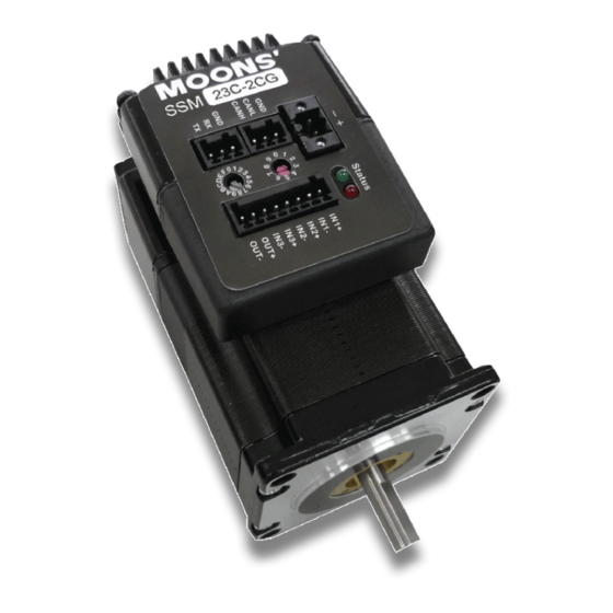
- Page 1 SSM23C Integrated Step-Servo Motor User Manual Rev. 1.0 AMP & MOONS’ Automation...
-
Page 2: Table Of Contents
2.3.2 Regeneration Clamp ................9 2.3.3 Current ....................10 3 Installation/Connections ............13 3.1 Connecting the Power Supply ............13 3.2 Connecting the SSM23C Communications ........14 3.2.1 Node ID ....................14 3.2.2 Setting the Bitrate .................14 3.3 Inputs and Outputs ................15 3.3.1 Connector Pin Diagram ................15 3.3.2 IN1 &... - Page 3 SSM23C User Manual 4.2.3 Electronic Gearing ................23 4.2.4 Positioning Error Fault ................23 4.2.5 Maximum Acceleration ................24 4.3 Node ID .....................24 4.3.1 I/O Definition ..................25 5 Tuning - Sampling ..............26 5.1 Velocity Control Loop (V Loop) ............26 5.1.1 Gain: The Velocity Proportional Term (VP) ...........27 5.1.2 IntegGain: The Velocity Integral Term (VI) ..........27...
- Page 4 SSM23C User Manual 5.8 Setting the Notch filter ..............40 6 SCL Test & Monitor ..............41 6.1 SCL Test ...................41 6.2 Motion Status ..................41 6.3 Monitor ....................42 6.4 I/O Status ..................42 6.5 Alarm ....................42 6.6 Drive Status ..................44 7 Troubleshooting ................. 45 8 Reference Materials ..............
-
Page 5: Introduction
SSM23C User Manual 1 Introduction Thank you for selecting the MOONS’ SSM23C Integrated Motor.The SSM line of integrated step-servo motors combines servo technology with an integrated motor to create a product with exceptional feature and broad capability. We hope our commitment to performance, quality and economy will result in a successful motion control project. -
Page 6: Block Diagram
SSM23C User Manual 1.2 Block Diagram SSM23C Block Diagram 12-70 VDC External 5 Volt DC Power Supply Power Supply RS-232 RS-232 TX, RX, GND 3.3VDC Internal Voltage Logic Temp Supply CANopen Det. CANopen MOSFET CANH, CANL, GND motor Power Amplifier... -
Page 7: Safety Instructions
SSM23C User Manual 1.3 Safety Instructions Only qualified personnel should transport, assemble, install, operate, or maintain this equipment. Properly qualified personnel are persons who are familiar with the transport, assembly, installation, operation, and maintenance of motors, and who meet the appropriate qualifications for their jobs. -
Page 8: Getting Started
2.2 Mounting the Hardware As with any step motor, the SSM23C must be mounted so as to provide maximum heat sinking and airflow. Keep enough space around the Integrated Motor to allow for airflow. •... -
Page 9: Choosing A Power Supply
2.3.1 Voltage The SSM23C is designed to give optimum performance between 24 and 48 Volts DC. Choosing the voltage depends on the performance needed and motor/drive heating that is acceptable and/ or does not cause a drive over-temperature. Higher voltages will give higher speed performance but will cause the SSM23C to produce higher temperatures. -
Page 10: Current
SSM23C User Manual 2.3.3 Current The maximum supply currents required by the SSM23C are shown in the charts below at different power supply voltage inputs. The SSM23C power supply current is lower than the winding currents because it uses switching amplifiers to convert a high voltage and low current into lower voltage and higher current. - Page 11 SSM23C User Manual SSM23C-2CG 70V Power Torque Continuous Boost Supply Current Full Load No Load Speed(RPS) SSM23C-3CG 24V Power Torque Continuous Boost Supply Current Full Load No Load Speed(RPS) SSM23C-3CG 48V Power Torque Continuous Boost Supply Current Full Load No Load Speed(RPS) Rev.
- Page 12 SSM23C User Manual SSM17C-2CG 48V Power Torque Continuous Boost Supply Current Full Load No Load Speed(RPS) Rev. 1.0 +86-400-820-9661 0006302011...
-
Page 13: Installation/Connections
SSM23C User Manual 3 Installation/Connections 3.1 Connecting the Power Supply Use 16 to 20-gauge wire to connect the SSM23 to a power supply. It contains an internal fuse connected to the “+” terminal that is not user replaceable. If a user serviceable fuse is desired, install a 4 amp fast acting fuse in line with the “+”... -
Page 14: Connecting The Ssm23C Communications
Locate the SSM23C within 2.5 meters of the PC. Plug the DB9 connector of the communication cable that came with the drive into the serial port of the PC. Plug the 3-pin spring clamp connector into the appropriate connector on the SSM23C. Secure the cable to the PC with the screws on the DB9 connector. -
Page 15: Inputs And Outputs
SSM23C User Manual 3.3 Inputs and Outputs The SSM23C has three optically isolated inputs that use 5 to 24V volts logict 3.3.1 Connector Pin Diagram Inside drive IN1+ IN1- IN2+ IN2- IN3+ IN3- OUT+ OUT- 3.3.2 IN1 & IN2 Inputs IN1 and IN2 digital inputs are designed for high speed digital input operation between 5 and 24 volts. -
Page 16: In3 Input
IN3- Output 3 Inputs Output 3 IN3+ SSM23C User Manual IN3- Connecting to Indexer with Sinking Outputs Connecting to Indexer with Sourcing Outputs Output 1 IN1+ SSM23 IN1- Indexer IN1+ Output 1+ 5-24V With Output 2 IN2+ High Sourcing Output 1-... -
Page 17: Programmable Output
SSM23C User Manual 3.3.4 Programmable Output The SSM23C drives feature one optically isolated digital output (OUT). This output can be set to automatically control a motor brake, to signal a fault condition, to indicate when the motor is moving or to provide an output frequency proportional to motor speed (tach signal). Or the output can be turned on and off by program instructions like Set Output (SO). - Page 18 OUT- SSM23C User Manual Connecting a Sourcing Output again 5 – 24 volt Power Supply relay OUT+ SSM23C 1N4935 suppression diode OUT- Driving a Relay Do not connect the output to more than 30 volts. The current through the output terminal must not exceed 100mA.
-
Page 19: Drive Configuration
SSM23C User Manual 4 Drive Configuration SSM Quick Tuner is the PC based software application used to configure, and perform servo tuning, drive testing and evaluation of the SSM. System servo control gains, drive functionality, and I/O configuration are set with Quick Tuner. It also contains an oscilloscope function to help set the servo control gains. -
Page 20: Restore
SSM23C User Manual 4.1.2 Restore The Restore button will reset all parameters in the drive to the ones set by the factory (defaults). Note - as this will erase all parameters that have been changed, it may be desired to save them to a file first. -
Page 21: Led Flashing
SSM23C User Manual 4.1.4 LED Flashing Clicking on this button will bring up a screen where the LED flashing for certain warnings can be masked. Alarm fault conditions are not allowed to be masked and will always be indicated by the drive’s LEDs. Masking alarm warnings only prevents the indication of the alarm by the LEDs. -
Page 22: Servo Enable/Disable
SSM23C User Manual Uses Check Sum The SSM Integrated Motor supports using a check sum in the communication protocol. For more reliable communications this option can be selected. Checksum is used automatically when the SSM is being configured, tuned or operated in the target environment. This can prevent mis- information being sent to or received back from the drive. -
Page 23: Basic Configuration
SSM can have the same number of steps/ revolution as the stepper. For example, SSM23C can be programmed to operate at 200 steps/rev, like a full step drive. If the system is working in degrees, the drive can be programmed to operate at 36,000 steps/rev resulting in an even number of steps (100) per degree. -
Page 24: Maximum Acceleration
SSM23C User Manual 4.2.5 Maximum Acceleration This sets the maximum level of acceleration for the motor. Even if the command input tries to demand a higher level of acceleration, the drive will only accelerate at the set maximum level. This value is also used as a quick stop when meeting with limit sensor or other stop commands. -
Page 25: I/O Definition
SSM23C User Manual 4.3.1 I/O Definition Options for IN1 are: • At end of travel, CW limit input will be closed • At end of travel, CW limit input will be open • Not used - generic programmable input Options for IN2 are: •... -
Page 26: Tuning - Sampling
SSM23C User Manual 5 Tuning - Sampling Being a servo motor, the SSM Integrated Motor employs sophisticated algorithms and electronics for controlling the torque, velocity and position of the motor to achieve a well behaved operation of the load. Because the motor encoder continuously tells the drive what the motor is doing, the drive can alter the current applied to the motor until the motor achieves the desired operation. -
Page 27: Gain: The Velocity Proportional Term (Vp)
SSM23C User Manual 5.1.1 Gain: The Velocity Proportional Term (VP) The simplest part of the Velocity Loop is the proportional, or VP, term. The drive applies current to the motor in direct proportion to the error. For example, if a motor is... -
Page 28: Position Control Loop
SSM23C User Manual 5.2 Position Control Loop The Position Control Loop is designed to provide the typical positioning control for a servo system. All positioning type operations use this loop including when operating in the Pulse & Direction Position Control Mode. The Position loop can also be used in the Velocity Control Mode when the Position over time control type option is selection or the Jog Mode is JM=1. -
Page 29: Deri Filter: Torque Command Filter Term (Ke)
SSM23C User Manual where: Un is the error in encoder counts Un-1 is the error of the previous sample 5.2.4 Deri Filter: Torque Command Filter Term (KE) A derivative control term can be rather noisy and even though it is effective in damping the positioning control, it can cause objectionable audible or observable noise to the system. -
Page 30: Frequency: Notch Filter Center Frequency
SSM23C User Manual 5.3.1 Frequency: Notch Filter Center Frequency This defines the center frequency - the frequency where the most gain reduction occurs. For now, finding the center frequency is a bit of a guessing game and different frequencies can be tried until the system resonance is eliminated. -
Page 31: Getting Ready For Tuning
SSM23C User Manual 5.4 Getting Ready for Tuning Before testing a servo-system a few more parameters need to be entered. These include the Max Speed, Acceleration and Distance (or time) requirements of the sample move. The proper profile shape of the move is needed to operate the load in the same way as what will be expected during online operation. -
Page 32: Tuning The Velocity Loop
SSM23C User Manual The mechanical system should be set up as close to the final configuration as possible so that the tuning represents what will be expected. The critical components include the coupler, mechanical interface ,and similar frictional and inertial loads. As... -
Page 33: Performing A Move
SSM23C User Manual Sample Once: after the Start button is clicked, a single move is performed, the motor stops, and the results will be displayed. Sample Continuously: after the Start button is clicked, the move will be repeated and the results displayed until the Stop button is clicked. - Page 34 SSM23C User Manual This first plot is performed with the default tuning values and no load added to the motor. The second plot is performed with higher gain values for the VP (25000) and VI (3000), as can be seen the velocity error decreases as the gains are increased.
-
Page 35: Adding In The Ff Gain (Kk) Parameter
SSM23C User Manual To get a good comparison between different plots where the gains have been changed, turn off the Auto Scale by clearing that check box below the plot screen. When auto scaling is turned off, the difference can be seen more clearly. -
Page 36: Verify The Drive Current
SSM23C User Manual With a large inertial load, the gain parameters, especially the VP and VI terms, may need to be set high to get a good response. The filter may then need to be decreased in value (lower frequency) to prevent ringing or oscillation. -
Page 37: Performing A Move
SSM23C User Manual Plot 1 & Plot 2: two different values can be selected for viewing in the scope window, in this case Actual Speed and Position Error are selected. For Position tuning these are typical values. Sample Move: move profile values are entered in the Sampling section. -
Page 38: Adjusting The Gain (Kp) And Deri Gain (Kd) Parameters
SSM23C User Manual 5.6.3 Adjusting the Gain (KP) and Deri Gain (KD) parameters Adjust the KP and KD parameters and observe the results. Increasing the KP may improve the positioning performance, but it may also cause the system to be more unstable. To counter this the KD can be increased. -
Page 39: Setting Up Auto Trigger
SSM23C User Manual 5.7.1 Setting up Auto Trigger When using Auto Trigger, the primary effort is to select the conditions that will trigger the sampling. Begin by selecting the desired trigger value in the Plot 1 list. This selection is what is monitored by the Auto Trigger, Plot 2 is not monitored. -
Page 40: Setting The Notch Filter
SSM23C User Manual Sample Continuously: when the Start button is clicked the capture is repeated each time the trigger condition is met until the Stop button is clicked. During continuous sampling the tuning gains can be changed at any time and will be updated automatically. This allows more dynamic... -
Page 41: Scl Test & Monitor
SSM23C User Manual 6 SCL Test & Monitor 6.1 SCL Test The SCL (Serial Command Language) Test tool is used to send commands to the serial port of the connected drive. A command can be entered manually in the Command window at the bottom of the screen. -
Page 42: Monitor
SSM23C User Manual 6.3 Monitor The Monitor tool allows the user to view five of nine different parameters at any one time. Each of the 5 dropdown lists contains the same 9 parameters that can be selected and displayed. These parameters are updated as part of the polling process and therefore the values may lag behind the actual value in the SSM. - Page 43 SSM23C User Manual Faults Position Error the drive exceeded the position fault limit as set by the PF (Position Fault) command Drive Overtemperature the DSP temperature exceeded 95 C or the drive internal PCB exceeded 85℃ Over Voltage the DC bus voltage exceeded 75 VDC...
-
Page 44: Drive Status
SSM23C User Manual 6.6 Drive Status The Drive Status is an overall indication of the drive condition. In a typical application this is the most common information that should be collected from the drive. Collecting the drive status information allows the system controller to keep track of drive operations and conditions. -
Page 45: Troubleshooting
7 Troubleshooting LED Error Codes The SSM23C uses red and green LEDs to indicate status. When the motor is enabled, the green LED flashes slowly. When the green LED is solid, the motor is disabled. Errors are indicated by combinations of red and green flashes as shown below. This feature can be disabled for certain warnings but not for alarms. -
Page 46: Reference Materials
SSM23C User Manual 8 Reference Materials 8.1 Mechanical Outlines L±1 56.4 MAX 47.14 50.9 Model Length“L” Length“M” SSM23C-2CG 92.4 SSM23C-3CG 114.4 56.4 MAX L±1 47.14 50.9 Length“L” Length“M” Model SSM23C-2CG 92.4 SSM23C-3CG 114.4 Rev. 1.0 +86-400-820-9661 0006302011... -
Page 47: Technical Specifications
Amplifier Type Dual H-Bridge, 4 Quadrant Current Control 4 state PWM at 20 KHz SSM23C-2CG: Up to 1.0N•m Continuous(1.3 N•m Boost) Output Torque SSM23C-3CG: Up to 1.5N•m Continuous(2.0 N•m Boost) Power Supply External 12 - 70 VDC power supply required... -
Page 48: Torque-Speed Curves
SSM23C User Manual 8.3 Torque-Speed Curves Note: all torque curves were measured at 20,000 steps/rev. Note: 5 amp rating is continuous,7.5 amp rating is boost Continuous SSM23 C -2 C G Boost Speed(rps) 连续运行 SSM23 C -3 C G 短时运行... -
Page 49: Scl Command Reference
In SCL mode, the SSM23C receives commands from the host, executing them immediately or sending them to a command buffer and then executing them directly from the buffer. It cannot, however, create a stored program for stand-alone operation. - Page 50 The SCL Utility Software Manual contains the complete command listing as well as instructions on connecting and configuring the SSM23C for use in SCL mode, using the Data Registers and the Protocol command. It also contains detailed information on: •...
-
Page 51: Contacting Moons
SSM23C User Manual 9 Contacting MOONS’ Service Center +86-400-820-9661 Headquarters No. 168 Mingjia Road Industrial Park North Minhang District Shanghai 201107, P.R. China Tel: +86(0)21-52634688 Fax: +86(0)21-62968682 E-mail: info@moons.com.cn MOONS' Industries (Europe) S.r.l. Via Torri Bianche n.1 20059 Vimercate(MB) Italy...
Need help?
Do you have a question about the SSM23C and is the answer not in the manual?
Questions and answers