
Related Manuals for Moons' SSDC-A Series


Summary of Contents for Moons' SSDC-A Series
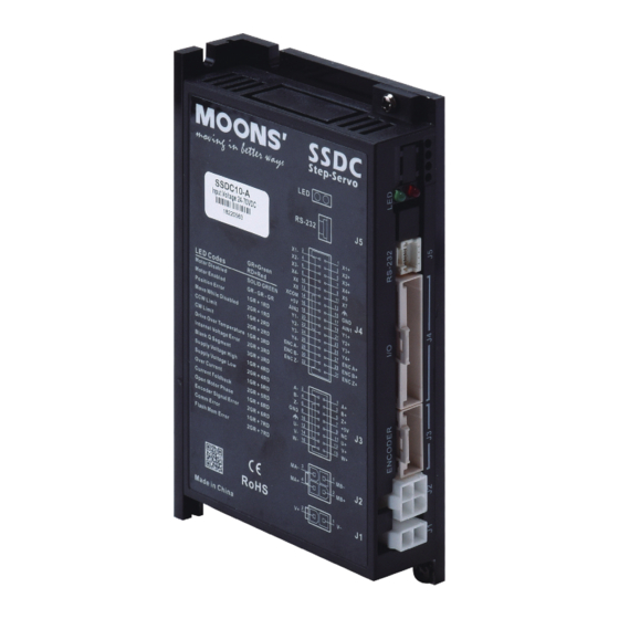
- Page 1 SSDC-A Step-Servo System Hardware Manual SSDC03-A SSDC06-A SSDC10-A SHANGHAI AMP&MOONS’ AUTOMATION CO.,LTD. Rev. 1.0 10/19/2018...
-
Page 2: Table Of Contents
SSDC-A Hardware Manual Contents 1 Introduction ..........................4 1.1 Features ......................... 4 1.2 Block Diagram ........................ 5 1.3 Safety Instructions ......................6 2 Getting Started ........................... 7 2.1 Installing Software ......................8 2.2 Connecting to the PC using RS-232 ................9 2.3 Choosing the Right COM Port .................. - Page 3 SSDC-A Hardware Manual 7.2.7 Regeneration Clamp RC880 ................. 47 7.2.8 USB Adapter ....................47 7.3 Mating Connector to the Drive ..................48 8 Contacting MOONS’ ........................ 49 Rev. 1.0 400-820-9661 10/19/2018...
-
Page 4: Introduction
SSDC-A Hardware Manual 1 Introduction Thank you for selecting the MOONS’ SSDC series Step-Servo drive and motor. SSDC series combines servo technology with a stepper motor to create a product with exceptional feature and broad capability. The SSDC series is a high performance, intelligent Step-Servo system with multi-axes field bus control. -
Page 5: Block Diagram
SSDC-A Hardware Manual 1.2 Block Diagram SSDC Block Diagram Power Supply: Filter SSDC06/10: 24-70VDC SSDC03: 12-48VDC Internal DC Input Voltage Logic Power Temp. Converter Supply Det. High Speed Input Mosfet Digital Software Optical Filter Filter Ioslation Power Amplifier Over Current Input Det. -
Page 6: Safety Instructions
SSDC-A Hardware Manual 1.3 Safety Instructions Only qualified personnel should transport, assemble, install, operate, or maintain this equipment. Properly qualified personnel are persons who are familiar with the transport, assembly, installation, operation, and maintenance of motors, and who meet the appropriate qualifications for their jobs. To minimize the risk of potential safety problems, all applicable local and national codes regulating the installation and operation of equipment should be followed. -
Page 7: Getting Started
SSDC-A Hardware Manual 2 Getting Started The following items are needed: • A 12-70VDC power supply, see the section below entitled “Choose a Power Supply” for helping to choose the right one. • A compatible SS or RS motor, please see the section below entitled “Recommended Motor” •... -
Page 8: Installing Software
SSDC-A Hardware Manual 2.1 Installing Software Step-Servo Quick Tuner is the PC based software application used to configure, and perform servo tuning, drive testing and evaluation of the step-servo products. System servo control gains, drive functionality and I/O configuration are set with Step-Servo Quick Tuner. It also contains an oscilloscope function to help set the servo control gains. -
Page 9: Connecting To The Pc Using Rs-232
SSDC-A Hardware Manual 2.2 Connecting to the PC using RS-232 Connector J5 is RS-232 communication port, please use the included RS-232 cable to connect the drive and PC. Use the Step-Servo Quick Tuner software to configure the drive parameter, tuning, monitoring the status of drive and motor. Definition DGND 2.3 Choosing the Right COM Port... -
Page 10: Connecting The Power Supply
SSDC-A Hardware Manual 2.4 Connecting the Power Supply The SSDC series step-servo drive and motor are shipped with a power cable, 2 meters long. Connect the red wire to the positive of the power supply. Connect the black wire to the negative of the power supply. -
Page 11: Choosing A Power Supply
SSDC-A Hardware Manual 2.5 Choosing a Power Supply The main considerations when choosing a power supply are the voltage and current requirements for the application. 2.5.1 Voltage The SSDC drive is designed to give optimum performance between 24 and 48 Volts DC. Choosing the voltage depends on the performance needed and motor/drive heating that is acceptable and/or does not cause a drive over-temperature. -
Page 12: Current
SSDC-A Hardware Manual 2.5.2 Current The maximum supply currents required by the SSDC series step servo drive and motor are shown below in chats at different power supply voltage input. The SSDC drive power supply current is lower than the winding currents because it uses switching amplifiers to convert a high voltage and low current into low voltage and high current. - Page 13 SSDC-A Hardware Manual AM11RS3DMA 24V Power Torque Continuous Boost Supply Current Full Load No Load Speed (rps) □ □ AM17SS1DG -N AM17RS1DM 24V Power Torque Continuous Boost Supply Current Full Load No Load Speed (rps) □ □ AM17SS1DG AM17RS1DM 48V Power Torque Continuous Boost...
- Page 14 SSDC-A Hardware Manual □ □ AM17SS2DG -N AM17RS2DM 24V Power Torque Continuous Boost Supply Current Full Load Full Load Speed (rps) □ □ AM17SS2DG -N AM17RS2DM 48V Power Torque Continuous Boost Supply Current Full Load Full Load Speed (rps) □ □...
- Page 15 SSDC-A Hardware Manual □ □ AM17SS3DG -N AM17RS3DM 48V Power Torque Continuous Boost Supply Current Full Load Full Load Speed (rps) □ □ AM17SS4DG -N AM17RS4DM 24V Power Torque Continuous Boost Supply Current Full Load Full Load Speed (rps) □ □...
- Page 16 SSDC-A Hardware Manual □ □ AM23SS2DG -N AM23RS2DM 24V Power Torque Continuous Boost Supply Current Full Load Full Load Speed (rps) □ □ AM23SS2DG -N AM23RS2DM 48V Power Torque Continuous Boost Supply Current Full Load Full Load Speed (rps) □ □...
- Page 17 SSDC-A Hardware Manual □ □ AM23SS3DG -N AM23RS3DM 24V Power Torque Continuous Boost Supply Current Full Load Full Load Speed (rps) □ □ AM23SS3DG -N AM23RS3DM 48V Power Torque Continuous Boost Supply Current Full Load Full Load Speed (rps) □ □...
- Page 18 SSDC-A Hardware Manual □ □ AM24SS3DG -N AM24RS3DM 24V Power Torque Continuous Boost Supply Current Full Load Full Load Speed (rps) □ □ AM24SS3DG -N AM24RS3DM 48V Power Torque Continuous Boost Supply Current Full Load Full Load Speed (rps) □ □...
- Page 19 SSDC-A Hardware Manual AM34SS1DGA-N AM34RS1DMA 24V Power Torque Continuous Boost Supply Current Full Load Full Load Speed (rps) AM34SS1DGA-N AM34RS1DMA 48V Power Torque Continuous Boost Supply Current Full Load Full Load Speed (rps) AM34SS1DGA-N AM34RS1DMA 70V Power Torque Continuous Boost Supply Current Full Load Full Load...
- Page 20 SSDC-A Hardware Manual AM34SS3DGA-N AM34RS3DMA 24V Power Torque Continuous Boost Supply Current Full Load Full Load Speed (rps) AM34SS3DGA-N AM34RS3DMA 48V Power Torque Continuous Boost Supply Current Full Load Full Load Speed (rps) AM34SS3DGA-N AM34RS3DMA 70V Power Torque Continuous Boost Supply Current Full Load Full Load...
- Page 21 SSDC-A Hardware Manual AM34SS5DGA-N AM34RS5DMA 24V Power Torque Continuous Boost Supply Current Full Load Full Load Speed (rps) AM34SS5DGA-N AM34RS5DMA 48V Power Torque Continuous Boost Supply Current Full Load Full Load Speed (rps) AM34RS5DMA AM34SS5DGA-N 70V Power Torque Continuous Boost Supply Current Full Load Full Load...
-
Page 22: Connecting The Motor
SSDC-A Hardware Manual 2.6 Connecting the Motor The SS/RS motors have two cables. One is the motor power cable, the other one is the encoder feedback cable. Plug the motor power cable into the motor connector on the drive and plug the encoder feedback cable into the encoder feedback connector on the drive. -
Page 23: Inputs And Outputs
SSDC-A Hardware Manual 3 Inputs and Outputs SSDC inputs and outputs include: • 8 optically isolated digital inputs,5 - 24VDC logic • 4 Optically isolated, Open Collector, 30V/100 mA max, • 2 analog inputs can be configured to 0-5V, 0-10V, ±5V or ±10V signal ranges •... -
Page 24: Digital Inputs
SSDC-A Hardware Manual 3.1 Digital Inputs 3.1.1 X1, X2, X3 and X4 Digital Inputs X1, X2: Optically isolated, differential, 5-24VDC; Minimum pulse width = 250ns, Maximum pulse frequency = 2MHz; X3, X4: Optically isolated, differential, 5-24VDC; Minimum pulse width = 100μs, Maximum pulse frequency = 5KHz X1 can be configured as general purpose input X2 can be configured as general purpose input... -
Page 25: X5, X6, X7 And X8 Digital Inputs
SSDC-A Hardware Manual 3.1.2 X5, X6, X7 and X8 digital Inputs X5 ~ X8: Optically isolated, differential, 5-24VDC; Minimum pulse width = 100μs, Maximum pulse frequency = 5KHz;X5可作为使能信号输入口或通用输入口。 X5 can be configured as servo on input or general purpose input X6 can be configured as alarm reset signal input or general purpose input X7 can be configured as Touch Probe 1 trigger input or general purpose input X8 can be configured as Touch Probe 2 trigger input or general purpose input... -
Page 26: Digital Outputs
SSDC-A Hardware Manual 3.2 Digital Outputs Y1, Y2, Y3 and Y4 Digital Outputs • Y1 can be configured as alarm signal output. It can also be configured as static in position signal output(static, checking in position when motor is stopped) ,or as dynamic in position signal output (dynamic, checking in position all the time.) •... - Page 27 SSDC-A Hardware Manual 5 - 24V Power Su pply – Load Y1/2/3/4+ SSDC Y1/2/3/4- Connecting a sourcing output to load 5 - 24V Power Su pply – Y1/2/3/4+ SSDC Y1/2/3/4- Connecting a sinking output to PLC's input 5 - 24V Power Su pply –...
-
Page 28: Analog Inputs
SSDC-A Hardware Manual 3.3 Analog Inputs SSDC series drive has two analog signal inputs which can accept signal range of 0-5V, 0-10V, ±5V and ±10V. The drive can be configured to operate at velocity mode or position mode that is proportional to the analog input. -
Page 29: Secondary Encoder Input
SSDC-A Hardware Manual 3.5 Secondary Encoder Input SSDC series supports 2-way encoder feedback, one way connect to the motor encoder position feedback, the other way connect to the load side position feedback such as scale, connect to the ENC A+/-,ENC B+/-,ENC Z+/-, the secondary encoder input can be accepted both of single- ended and differential signal. -
Page 30: Mounting The Drive
SSDC-A Hardware Manual 4 Mounting the Drive Use the M3 or M4 screw to mount the SSDC series drive .The drive should be securely fastened to a smooth, flat metal surface will help conduct heat away from the chassis. If this is not possible, forced airflow from a fan maybe required to prevent the drive from overheating. -
Page 31: Reference Materials
SSDC-A Hardware Manual 6 Reference Materials 6.1 Drive Mechanical Outlines Model SSDC03-A SSDC06-A SSDC10-A Rev. 1.0 400-820-9661 10/19/2018... -
Page 32: Technical Specifications
SSDC-A Hardware Manual 6.2 Technical Specifications Power Amplifier Amplifier Type Dual H-Bridge, 4 Quadrant Current Control 4 state PWM at 20 KHz SSDC03: Continuous Current 3A max, Boost Current 4A max (1.5s), current limitation auto set-up by attached motor SSDC06: Output Current Continuous Current 6A max, Boost Current 7.5A max (1.5s), current limitation auto set-up by attached motor SSDC10:... -
Page 33: Recommended Motors
SSDC-A Hardware Manual 6.3 Recommended Motors Permissible Overhung Load(N) Rotor Encoder Maximum Frame Permissible Torque Mass Drive Inertia Resolution Speed Size Model Thrust Distance(L) from Shaft End(mm) Load counts/rev AM11RS1DMA 0.065 AM11RS2DMA SSDC03 0.08 AM11RS3DMA 0.125 AM17RS1DM□ 0.26 4096 AM17RS2DM□ 0.42 AM17RS3DM□... -
Page 34: Motor Dimensions (Unit:mm)
SSDC-A Hardware Manual 6.4 Motor Dimensions (Unit:mm) AM11 Series 16.2 4-M2.5 Depth 2.5 Min 23±0.1 Model AM11RS1DMA 43.8 AM11RS2DMA 52.9 φ22-0.052 4.5±0.1 φ5-0.012 AM11RS3DMA 64.1 AM17 Series 42.3 4-M3 Depth 4.5Min Model Connector On Cable AM17RS1DMA 59.5 φ6 Motor cable AM17RS1DMB 59.5 φ5... - Page 35 SSDC-A Hardware Manual AM23 Series 56.3 47.14 4-V5.1 V38.1 Model Connector On Cable AM23RS2DMA 77.5 Motor cable φ8 Housing: 39-01-3048 (Molex),1pcs AM23RS2DMB 5.85 77.5 φ6.35 Crimp: 39-00-0038 (Molex),4pcs AM23RS3DMA 99.5 φ8 Encoder cable AM23RS3DMB 5.85 99.5 φ6.35 Housing: 1-1827864-6 (Tyco),1pcs 连Crimp: 1-1827569-2 (Tyco),11pcs AM23RS4DMA 102.5...
- Page 36 SSDC-A Hardware Manual AM24 Series 47.14 4-V4.5 V38.1 Model Connector On Cable Motor cable AM24RS3DMA φ10 Housing: 39-01-3048 (Molex),1pcs Crimp: 39-00-0038 (Molex),4pcs Encoder cable Housing: 1-1827864-6 (Tyco),1pcs AM24RS3DMB 20.6 φ8 Crimp: 1-1827569-2 (Tyco),11pcs Motor cable AM24SS3DGA-N φ10 Housing: 39-01-3048 (Molex),1pcs Crimp: 39-00-0038 (Molex),4pcs Encoder cable Housing: 1-1827864-0 (Tyco),1pcs...
- Page 37 SSDC-A Hardware Manual AM34 Series 69.6 4-Φ6.5 Φ73.025 Model Connector On Cable Motor cable AM34RS1DMA Housing: 39-01-3048 (Molex),1pcs Crimp: 39-00-0038 (Molex),4pcs AM34RS3DMA 117.5 Encoder cable Housing: 1-1827864-6 (Tyco),1pcs AM34RS5DMA Crimp: 1-1827569-2 (Tyco),15pcs Motor cable AM34SS1DGA-N Housing: 39-01-3048 (Molex),1pcs Crimp: 39-00-0038 (Molex),4pcs AM34SS3DGA-N 117.5 Encoder cable...
- Page 38 SSDC-A Hardware Manual AM17SS-N-BR01 Series(With brake) 42.3 4-M3 Depth 4.5Min Ø22 73.5 Model Connector On Cable AM17SS1DGA-N-BR01 59.5 φ6 Motor cable AM17SS1DGB-N-BR01 59.5 φ5 Housing: 39-01-3048 (Molex),1pcs AM17SS2DGA-N-BR01 φ6 Crimp: 39-00-0038 (Molex),4pcs AM17SS2DGB-N-BR01 φ5 AM17SS3DGA-N-BR01 73.5 Encoder cable φ6 AM17SS3DGB-N-BR01 73.5 φ5 Housing: 1-1827864-0 (Tyco),1pcs...
- Page 39 SSDC-A Hardware Manual AM23SS-N-BR01系列 Series(With brake) 56.3 47.14 4-Ø5.1 Ø38.1 Model Connector On Cable AM23SS2DGA-N-BR01 77.5 φ8 Motor cable Housing: 39-01-3048 (Molex),1pcs AM23SS2DGB-N-BR01 5.85 77.5 φ6.35 Crimp: 39-00-0038 (Molex),4pcs AM23SS3DGA-N-BR01 99.5 φ8 Encoder cable AM23SS3DGB-N-BR01 5.85 99.5 φ6.35 Housing: 1-1827864-0 (Tyco),1pcs Crimp: 1827569-2 (Tyco),15pcs AM23SS4DGA-N-BR01 102.5...
- Page 40 SSDC-A Hardware Manual AM24SS-N-BR01 Series(With brake) 47.14 4-Ø4.5 Ø38.1 Model Connector On Cable Motor cable AM24SS3DGA-N-BR01 φ10 Housing: 39-01-3048 (Molex),1pcs Crimp: 39-00-0038 (Molex),4pcs Encoder cable Housing: 1-1827864-0 (Tyco),1pcs AM24SS3DGB-N-BR01 20.6 φ8 Crimp: 1827569-2 (Tyco),15pcs Specification of brake for NEMA24 motor Voltage Torque Reactive time...
- Page 41 SSDC-A Hardware Manual AM34SS-N-BR01 Series(With brake) 69.6 4-Ø6.5 Ø73.025 45.5 Model Connector On Cable Motor cable AM34SS1DGA-N-BR01 Housing: 39-01-3048 (Molex),1pcs Crimp: 39-00-0038 (Molex),4pcs AM34SS3DGA-N-BR01 117.5 Encoder cable Housing: 1-1827864-0 (Tyco),1pcs AM34SS5DGA-N-BR01 Crimp: 1827569-2 (Tyco),15pcs Specification of brake for NEMA34 motor Voltage Torque Reactive time...
-
Page 42: Torque Curves
SSDC-A Hardware Manual 6.5 Torque Curves AM11RS Series AM11RS1DMA Continuous Continuous Continuous AM11RS2DMA AM11RS3DMA Boost Boost Boost Speed(rps) Speed(rps) Speed(rps) AM17SS/RS Series □ □ □ AM17SS1DG Continuous Continuous Continuous AM17SS2DG AM17SS3DG □ □ □ AM17RS1DM Boost AM17RS2DM AM17RS3DM Boost ... -
Page 43: Motor Numbering System
SSDC-A Hardware Manual 6.6 Motor Numbering System AM17 SS 3 D G A-N Frame Size Mechanical Option 11,17,23,24,34 A=Shaft diameter 11:φ5 Step Servo 17:φ6 SS、RS 23:φ8 24:φ10 Motor Size 34:φ14 1 = 1 Stack B=Shaft diameter 2 = 2 Stack 17:φ5 Encoder 3 = 3 Stack... -
Page 44: Accessories
SSDC-A Hardware Manual 7 Accessories 7.1 Standard Accessories(Included) • -A Type Model Number Catagory Vendor Description 1103-200 Cable Power supply cable 2101-150 Cable RS-232 configuration cable 39-01-3048 Housing Molex Motor connector housing (J2) 501646-1600 Housing Molex Encoder connector housing (J3) 501646-3200 Housing Molex... -
Page 45: Extended Motor Cable(For Ssdc Drive And Am11Rs Motor
SSDC-A Hardware Manual 7.2.2 Extended motor cable(For SSDC drive and AM11RS motor) Housing:51065-0600(Molex) Housing: 39-01-3048(Molex) Crimp:50212-8000(Molex) Crimp: 39-00-0038(Molex) Length(L) Description Model Wiring Diagram 2109-100 Standard type PIN(J1) Color (Signal) PIN(J2) 2109-300 Standard type Blue(B-) 2109-500 Standard type Red(B+) 2109-1000 Standard type Green(A-) 2109-100-C02 Flexbile type,... -
Page 46: Extended Encoder Cable(For Ssdc Drive And Am11Rs Motor
SSDC-A Hardware Manual 7.2.4 Extended encoder cable(For SSDC drive and AM11RS motor) Housing:501646-1200(Molex) Housing: J21DF-16V-KX-L(JST) Crimp:501648-1000(Molex) Crimp: SJ2F-002GF-P1.0(JST) Length(L) Description Model Wiring Diagram 2118-100 Standard type PINJ1) Color (Signal) PIN(J2) PIN(J1) Color (Signal) PIN(J2) 2118-300 Standard type Blue(A+) Brown(U+) 2118-500 Standard type Blue/Black(A-) Brown/Black(U-) -
Page 47: Extended Encoder Cable(For Ssdc Drive And Am17/23/24/34Rs Motor
SSDC-A Hardware Manual 7.2.6 Extended encoder cable(For SSDC drive and AM17/23/24/34RS motor) Housing: Housing: 1-1903130-6(TYCO) 501646-1600(Molex) Crimp: Crimp: 501648-1000(Molex) 1903120-1(TYCO) Model Length(L) Description Wiring Diagram PINJ1) PIN(J2) PIN(J1) PIN(J2) 2116-100 Standard type Color (Signal) Color (Signal) 2116-300 Standard type Blue(A+) Brown(U+) 2116-500 Standard type... -
Page 48: Mating Connector To The Drive
SSDC-A Hardware Manual 7.3 Mating Connector to the Drive Description Vender Power Connector Housing:39-01-3028 Crimp:39-00-0038 Molex Motor Connector Housing:39-01-3048 Crimp:39-00-0038 Molex Encoder Connector Housing:501646-1600 Crimp:501648-1000 Molex I/O Connector Housing:501646-3200 Crimp:501648-1000 Molex RS-232 Connector Housing:ZER-04V-S Crimp: SZE-002T-P0.3 Rev. 1.0 400-820-9661 10/19/2018... -
Page 49: Contacting Moons
SSDC-A Hardware Manual 8 Contacting MOONS’ Service Center +86-400-820-9661 MOONS’Headquarter Ningbo Room 309, Tower B, Taifu Plaza, 565 Jiangjia Road, 168 Mingjia Road, Minhang District, Shanghai 201107, Jiangdong District, Ningbo, 315040, P.R. China P.R. China Tel: +86 (0)574 87052739 Tel: +86 (0)21 52634688 Fax:+86 (0)574 87052365 Fax:+86 (0)21 52634098 Guangzhou...
Need help?
Do you have a question about the SSDC-A Series and is the answer not in the manual?
Questions and answers