
Related Manuals for Anritsu MS9710C


Summary of Contents for Anritsu MS9710C
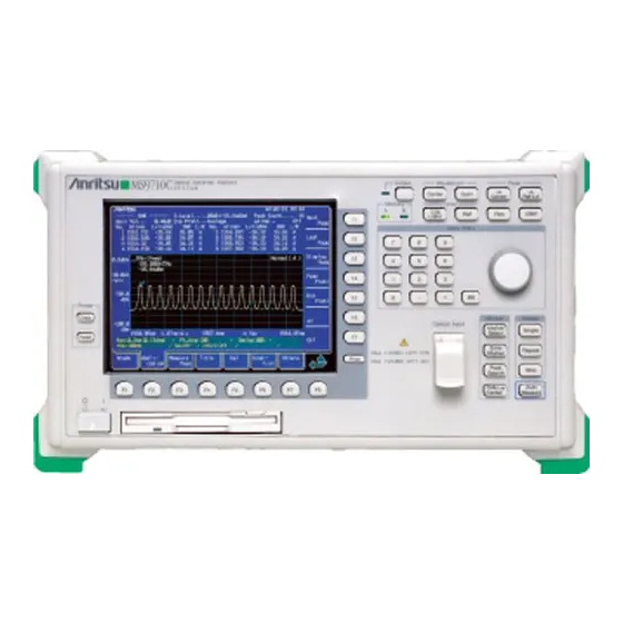
- Page 1 MS9710C Optical Spectrum Analyzer Remote Control Operation Manual Read this manual before using the equipment. Keep this manual with the equipment.
- Page 3 5-10-27, Minamiazabu, Minato-ku, Tokyo 106-8570 Japan / Phone: 81-3-3446-1111 ANRITSU CORPORATION Document No.: M–W1580AE Printed in Japan...
- Page 4 Optical Spectrum Analyzer Remote Control Operation Manual Third Edition To ensure that the MS9710C Optical Spec- trum Analyzer is used safely, read the safety information in the MS9710C Optical Spectrum Analyzer Operation Manual first. Keep this manual with the Optical Spectrum Analyzer.
- Page 5 1999 (First Edition) April 2000 (Third Edition) Copyright © 1999-2000, ANRITSU CORPORATION. All rights reserved. No part of this manual may be reproduced without the prior written permission of the publisher. The contents of this manual may be changed without prior notice.
- Page 6 About This Manual This manual explains remote control of the MS9710C optical spectrum analyzer. You can control the MS9710C and transfer measurement results into the computer connected to the GPIB/RS-232C interface port of the MS9710C.
-
Page 7: Table Of Contents
........... iii About This Manual ........Section 1 Introduction ........1.1 Overview ..............1.2 MS9710C Remove Control Functions ....... 1.3 Interface Port Application Selection Function .... 1.4 Examples of Setups Using GPIB/RS-232C ....Section 2 How to Connect ......2.1 Connecting Devices Using GPIB Cables .... - Page 8 6.1 Differences in Syntax between Listener Input Formats and Talker Output formats ......... 6.2 Response Message Functional Elements ....Section 7 Common Commands ....7.1 Classification of MS9710C-Supported Common Commands by Group Function ............. 7.2 Classification of Supported Commands and References ..............
- Page 9 Appendix C Comparison Table of GPIB Commands of Controller ..Appendix D Example of Program Used on PC9801 ........Appendix E MS9710C and MV02 (MS9703A) Command Compatibility Table ..Appendix F MS9710C and HP Optical Spectrum Analyzer (HP71450A/71451A) Com- mand Compatibility Table ..
-
Page 10: Section 1 Introduction
Section 1 Introduction This section outlines the remote control functions of the MS9710C optical spec- 1 1 1 trum analyzer. Overview ............MS9710C Remove Control Functions ... Interface Port Application Selection Function .. Examples of Setups Using GPIB/RS-232C ... -
Page 11: Overview
Tracking measurement with the tunable laser source Interface Port Application Selection Function The MS9710C comes standard with a GPIB interface bus and an RS-232C inter- face. Application of these interface ports can be selected from the panel. External controller connection port: Select GPIB or RS-232C. -
Page 12: Examples Of Setups Using Gpib/Rs-232C
1.4 Examples of Setups Using GPIB/RS-232C Examples of Setups Using GPIB/RS-232C 1 1 1 (1) Standalone type Waveforms measured with the MS9710C are output to the printer. MS9710C Printer GPIB (2) Control by host computer The MS9710C is controlled by a computer automatically/remotely. - Page 13 Section 1 Introduction 1-4.
-
Page 14: Section 2 How To Connect
This section explains how to connect GPIB and RS-232C cables between the MS9710C and external devices such as a host computer, personal computer, and printer. This section also explains how to set the interfaces of the MS9710C. Connecting Devices Using GPIB Cables .. -
Page 15: Connecting Devices Using Gpib Cables
“08” is battery-backed up. If you use this address, the address need not be set again. If you want to change the address, place the MS9710C in the local mode, press the GPIB Address function key on the “Others” card, then enter a new address with keyboard keys or an encoder. -
Page 16: Connecting A Device Using An Rs-232C Cable
2.2 Connecting a Device Using an RS-232C Cable Connecting a Device Using an RS-232C Cable Connect the RS-232C connector (D-sub, 9-pin, male) and the RS-232C connector with an RS-232C cable. Back panel of MS9710C RS-232C External device RS-232C RS-232C cable Note: RS-232C connectors are available in 9-pin and 25-pin types. -
Page 17: Rs-232C Interface Signal Connection Diagrams
Section 2 How to Connect 2.2.1 RS-232C interface signal connection diagrams The following diagrams show connections of RS-232C interface signals between the MS9710C and two types of personal computers. Connection with PC98 personal computer PC98 personal MS9710C computer CD (NC) 1... -
Page 18: Setting Interface Conditions For The Connection Port
2.2 Connecting a Device Using an RS-232C Cable 2.2.2 Setting interface conditions for the connection port When controlling the MS9710C automatically/remotely from a computer, set in- terface conditions for the connection port. Press the RS-232C Prmtr function key on the “Others” card and select “RS232C”... - Page 19 Section 2 How to Connect...
-
Page 20: Section 3 Standards
Section 3 Standards This section explains the MS9710C’s GPIB standard, RS-232C standard, and device message list. GPIB Standard ..........RS-232C Standard ........Device Message List ........3.3.1 IEEE 488.2 common commands and the commands supported by the MS9710C ........3.3.2 Status Messages ........ -
Page 21: Gpib Standard
Section 3 Standards GPIB Standard The standard for the GPIB of the MS9710C is summarized below. Item Standard value and description Conforms to IEEE 488.2. Function MS9710C can be controlled from an external controller. MS9710C can control a printer. SH1: All of source handshake functions are supported. -
Page 22: Device Message List
These two types of commands are explained on the following pages. Program commands include device-dependent commands which are exclusively used for controlling the MS9710C and IEEE 488.2 common commands. IEEE 488.2 common commands are program commands which are commonly appli- cable to other IEEE 488.2-ready measuring instruments (including the... - Page 23 A FIFO (first in first out) type memory area that stores DABs (program and query messages) temporarily before analysis of syntax and execution. The input buffer size of the MS9710C is 256 bytes. Output queue An FIFO-type queue memory area. All DABs (response messages) output from a device to a controller are stored in this memory until they have been read by the controller.
-
Page 24: Ieee 488.2 Common Commands And The Commands Supported By The Ms9710C
IEEE 488.2 common commands and the commands supported by the MS9710C The table below lists 39 common commands specified by IEEE 488.2. Among these commands, the commands supported by the MS9710C are marked with . Mnemonic Fully spelled out command name Standardized by IEEE 488.2... -
Page 25: Status Messages
Section 3 Standards 3.3.2 Status Messages Shown below is the structure of the service request summary message set in the status byte register of the MS9710C. Summary Bit Configuration of Status Byte Register Bit 7 Bit 6 Bit 5 Bit 4... - Page 26 3.3 Device Message List To preceding page Logical OR END summary bit & Reserved & Reserved & Reserved (∗RST, wavelength calibration, automatic optical axis Execution completion & adjustment, or resolution calibration end) (power monitor 1-point measurement or sweep Execution completion &...
- Page 27 Section 3 Standards 3.3.3 MS9710C device message list A list of MS9710C-dependent program commands, program queries, and response messages is shown on the fol- lowing pages. MS9710C Device Message List (1/13) Device message Item Remarks Data Command Response request CNT λ...
-
Page 28: Ms9710C Device Message List
3.3 Device Message List MS9710C Device Message List (2/13) Device message Item Remarks Data Command Response request Resolu RES n RES? n : Resolution (nm) 9.69 -tion n : Value shown n = 0.05, 0.07, 0.1, on the right 0.2, 0.5, 1... - Page 29 Section 3 Standards MS9710C Device Message List (3/13) Device message Item Remarks Data Command Response request Analysis Envelope ANA ENV, r ANA? ENV, r r : Cut level (dB) r = 0.1 to 20.0 r = 0.1 to 20.0 ANA RMS, r, k...
- Page 30 3.3 Device Message List MS9710C Device Message List (4/13) Device message Item Remarks Data Command Response request Save/ Format 9.41 Recall File Delete DEL n n : File name 9.23 n : File name File Option FOPT a, b, c...
- Page 31 Section 3 Standards MS9710C Device Message List (5/13) Device message Item Remarks Data Command Response request Applica DFB-LD AP DFB, s, n DFB, s, n -tion s = 2NDPEAK s = 2NDPEAK = LEFT = LEFT = RIGHT = RIGHT...
- Page 32 3.3 Device Message List MS9710C Device Message List (6/13) Device message Function Remarks Data Command Response request Applica O.Amp AP AMP, PRM, AMP, PRM, -tion Parameter a, b, c, d, e, AMP, a, b, c, d, e, f, g, h, i, j, k...
- Page 33 Section 3 Standards MS9710C Device Message List (7/13) Device message Function Remarks Data Command Response request Applica- WDM Table AP WDM, WDM, TBL, d d is the Dip detection TBL, d, ∆λ, s ∆λ, s tion WDM, direction. ∆λ is the detection posi-...
- Page 34 3.3 Device Message List MS9710C Device Message List (8/13) Device message Function Remarks Data Command Response request n, λ 1, L1, λ 2, Applica APR? n is the number of peaks, λ x is the wavelength of peak -tion (analysis L2...
- Page 35 Section 3 Standards MS9710C Device Message List (9/13) Device message Function Remarks Data Command Response request Applica APR? MPKC, n n is the number of -tion Peak Count MPKC n = 0 to 50 peaks WDM, MPK, λ, Result APR?
- Page 36 3.3 Device Message List MS9710C Device Message List (10/13) Device message Function Remarks Data Command Response request Measure D.range DRG s DRG? 9.31 Mode Normal/ s = NORMAL s = NORMAL High = HIGH = HIGH Interval ITM s ITM? s : Time 9.45...
- Page 37 Section 3 Standards MS9710C Device Message List (11/13) Device message Item Remarks Data Command Response request Calibra- Wl-Offset WOFS n WOFS? 9.94 = ±xx.x tion Offset wavelength (nm) WCAL n WCAL? W-CAL1;EXT.LIGHT 9.92 Calibration n = 0: W-CAL m = 0: Calibration...
- Page 38 3.3 Device Message List MS9710C Device Message List (12/13) Device message Item Remarks Data Command Response request λ λ, l λ Marker Trace Marker TMK? : Wavelength (nm) or 9.87 λ λ = xxxx.xxxx = xxxx.xxxx (THz) λ = xx.xx (dBm , dB)
- Page 39 Section 3 Standards MS9710C Device Message List (13/13) Device message Item Remarks Data Command Response request 9.62 Peak→Center 9.86 TMkr→Center 9.63 Peak→Level Internal Copy 9.15 Printer Feed FED n n = Number of 9.40 n = 0 to 25 character lines...
-
Page 40: Section 4 Initial Setting
Section 4 Initial Setting The GPIB interface system is initialized at three levels. At level 1, “bus initializa- tion” is performed to place the system bus in the idle state. At level 2, “message exchange initialization” is performed to enable devices to receive program mes- sages. - Page 41 Section 4 Initial Setting E 488.1 defined the following two levels of GPIB system initialization. Initialization of bus: Interface functions of all devices connected to the bus are initialized by an IFC message from the controller. Initialization of devices: All devices on the GPIB are initialized with a GPIB bus command “DCL”, or only the specified devices are initialized to their specified states with a GPIB bus command “SDC.”...
- Page 42 “device initialization” function (level 3). However, it cannot use “bus initialization” (level 1) and “message exchange initialization” (level 2) functions. When controlled from a controller via a GPIB interface bus, the MS9710C can use all the above initialization functions (levels 1 to 3).
-
Page 43: Initialization Of Bus By Ifc Statement
Application example IFC @1 Explanation This function can be used when the MS9710C is controlled from a controller via a GPIB interface bus. On the GPIB corresponding to the specified select code, the IFC line is activated for about 100 µs (electrically set at the low level). When IFC@ is executed, interface functions of all devices connected to the GPIB bus line corresponding to the specified select code are initialized. - Page 44 4.1 Initialization of Bus by IFC Statement Let’s take a look at some device states set by the IFC statement. (1) Talker/listener: All talkers and listeners are set in the idle state (TIDS, LIDS) within 100 µs. (2) Controller: If the controller is not active (SACS: System control Active State), it enters the idle state “CIDS”...
-
Page 45: Initialization Of Message Exchange By Dcl And Sdc Bus Commands
DCL@103 Initializes message exchange only for the device at address 3. (Issue of SDC) Explanation This function can be used when the MS9710C is controlled by a controller via the GPIB interface bus. This statement initializes message exchange for all device on the GPIB corre- sponding to the specified select code or only for the specified devices. - Page 46 MAV bit is cleared. Section 7) (7) Automatic system configuration: ∗ADD and ∗DFL common commands are invalidated. (The MS9710C does not support these commands.) (8) Device function: All parts related to message exchange are set in the idle state. The device waits for a message from the controller.
-
Page 47: Initialization Of Devices By ∗Rst Command
∗RST Section 4 Initial Setting Initialization of Devices by ∗RST Command Format ∗RST Application example WRITE @103:"∗RST" Only the device at address 3 is initialized at level 3. Explanation The ∗RST(Reset) command, an IEEE 488.2 common command, is used to reset a specified device at level 3. - Page 48 4.3 Initialization of Devices by ∗RST Command Notes: ∗RST command does not affect the following items. 1. IEEE 488.1 interface state 2. Device address 3. Output queue 4. Service request enable register 5. Standard event status enable register 6. Power-on-status-clear flag setting 7.
- Page 49 Section 4 Initial Setting Table 4-1 lists MS9710C-dependent initial settings. The “Set condition” column lists device’s initial states set by the ∗RST command. In the “Battery backup” column, items battery-backed-up after power-off are marked with √. Table 4-1 MS9710C-dependent initial settings (1/3)
- Page 50 4.3 Initialization of Devices by ∗RST Command Table 4-1 MS9710C-dependent initial settings (2/3) Item group Item Set condition Battery backup √ Application Status √ DFB-LD ndB Width: 20 dB √ Side Mode: 2nd Peak √ FP-LD Mode Cut Lvl: 3 dB √...
- Page 51 Section 4 Initial Setting Table 4-1 MS9710C-dependent initial settings (3/3) Item group Item Set condition Battery backup Status Register Service request enable 0 (All inhibited) register Standard event status 0 (All inhibited) enable register Extended event status 0 (All inhibited)
-
Page 52: Device States At Power-On
(5) The device is set in the OQIS (Operation Complete Query Command Idle State). (6) The MS9710C does not support a ∗PSC command. So the standard event status register and standard event status enable register are cleared. Events are recorded after being cleared. - Page 53 (Not supported by the MS9710C) (5) Macro definition made with a ∗DMC command (Not supported by the MS9710C) (6) Macro definition made with an ∗EMC command (Not supported by the MS9710C) (7) Address received with a ∗PCB command (Not supported by the MS9710C) 4-14.
-
Page 54: Section 5 Listner Input Formats
Section 5 Listner Input Formats Device messages transferred between the controller and devices are classified into program messages and response messages. This section explains the formats of the program messages received by listeners. Summary of Listener Input Program Message Syntactical Notation ........5.1.1 Separator, terminator, and space before header ...... - Page 55 Section 5 Listner Input Formats A program message is a sequence of program message units. Each unit is a program command or query. The following figure shows that a program message made by connecting two program messages LOG 10 and RLV –20 with a program message unit separator is sent from a controller to a device to set the log scale to 10 dB/div and the reference level to –20 dBm.
-
Page 56: Summary Of Listener Input Program Message Syntactical Notation
5.1 Summary of Listener Input Program Message Syntactical Notation Summary of Listener Input Program Message Syntactical Notation This section gives a general description of program messages functional units ( Section 5.2) and program data formats ( Section 5.3). (Compound commands and common commands are excluded.) 5.1.1 Separator, terminator, and space before header (1) PROGRAM MESSAGE UNIT SEPARATOR... - Page 57 Section 5 Listner Input Formats (3) PROGRAM HEADER SEPARATOR Separate a program header and program data using one space and zero or more spaces. <Example 1> General format of simple command program header <PROGRAM HEADER> <white space> <white space> <PROGRAM DATA> <Example 2>...
-
Page 58: General Format Of Program Command Message
5.1 Summary of Listener Input Program Message Syntactical Notation 5.1.2 General format of program command message (1) Message without data specification <HR> HR: COMMAND PROGRAM HEADER <Examples> Automatic setting Single sweep start (2) Message with integer data <HR> NR1: Integer <Example>... - Page 59 Section 5 Listner Input Formats (5) Message with multiple pieces of program data (first: NR1) <HR> NR1 or NR2 NR1 or NR2 <Example> DATE ∆ 96, 10 Set the date to Oct. 10, 1996. (6) Character-only message that can use all seven ASCII bits <inserted'>...
-
Page 60: General Format Of Query Message
5.1 Summary of Listener Input Program Message Syntactical Notation 5.1.3 General format of query message Add ? at the end of a query program header. (1) Message without query data specification <HR> <Example> CNT? Request output of a center wavelength value. (2) Message with query data specification <HR>... -
Page 61: Program Message Functional Elements
Section 5 Listner Input Formats Program Message Functional Elements A device accepts a program message by detecting the terminator added at the end of the program message. Func- tional elements of the program message is described below. 5.2.1 <TERMINATED PROGRAM MESSAGE> <TERMINATED PROGRAM MESSAGE>... - Page 62 5.2 Program Message Functional Elements 5.2.2 <PROGRAM MESSAGE TERMINATOR> <PROGRAM MESSAGE TERMINATOR> is defined as follows. ∧ END <white space> ∧ END Refer to 5.2.3 <PROGRAM MESSAGE TERMINATOR> terminates a sequence of one or more fixed-length <PROGRAM MESSAGE UNIT> elements. Defined as a single ASCII code byte 0A (decimal 10).
- Page 63 Section 5 Listner Input Formats An EOI ON/OFF statement can be used to control the EOI line. EIO OFF is the default (the EOI line is not controlled). If the EOI ON statement is executed in advance, an EOI signal is issued along with the terminator LF when the last byte of the WRITE@ statement is issued.
-
Page 64: Program Message
5.2 Program Message Functional Elements 5.2.3 <white space> <white space> is defined as follows. <white space character> <white space character> is one of ASCII code bytes 00 to 09 and 0B to 20 (decimal values 0 to 9 and 11 to 32). This range includes ASCII control codes and space signals (except NL). -
Page 65: Program Message Unit
Section 5 Listner Input Formats 5.2.5 <PROGRAM MESSAGE UNIT SEPARATOR> <PROGRAM MESSAGE UNIT SEPARATOR> is defined as follows. <white space> <white space> is defined as follows. <white space character> Refer to 5.2.3 <PROGRAM MESSAGE UNIT SEPARATOR> divides a sequence of <PROGRAM MESSAGE UNIT> elements within the <PROGRAM MESSAGE>... -
Page 66: Command Message Unit>/
5.2 Program Message Functional Elements 5.2.7 <COMMAND MESSAGE UNIT>/<QUERY MESSAGE UNIT> (1) <COMMAND MESSAGE UNIT> is defined as follows. <PROGRAM DATA SEPARATOR> Refer to 5.2.11 <COMMAND <PROGRAM PROGRAM HEADER> HEADER SEPARATOR> <PROGRAM DATA> Refer to 5.2.8 Refer to 5.2.10 <PROGRAM DATA> XXX? Ø, –1ØØØ... -
Page 67: Command Program Header
Section 5 Listner Input Formats 5.2.8 <COMMAND PROGRAM HEADER> <COMMAND PROGRAM HEADER> is defined below. Each header can be followed by <white space>. <simple command <white space> program header> Refer to 5.2.3 Refer to (1) <compound command program header> Refer to (2) <common command program header>... - Page 68 An ASCII code byte, i.e., ASCII code byte 5F (decimal value 95 = underline). <simple command program header> The above rules for <program mnemonic> applies. For example, the MS9710C uses “SSI” as a mnemonic indicating “sweep.” It is also used as a “simple com- mand program header”...
- Page 69 A hierar- chical command structure can be handled effectively. <Example 1> To allow the MS9710C to use all device commands of another model (e.g., model MSXXXX), the compound program header would be :MSXXXX <Example 2>...
-
Page 70: Query Program Header
5.2 Program Message Functional Elements 5.2.9 <QUERY PROGRAM HEADER> <QUERY PROGRAM HEADER> is defined as follows: <white space> may be written before each header. <simple query <white space> program header> Refer to 5.2.3 Refer to (1) <compound query program header> Refer to (2) <common query program header>... - Page 71 A query header “CNT?” is used. Line 30: The listener device MS9710C that received the query header “CNT?” from the controller becomes a talker. The device is a controller that has become a listener, and it sends a response message 1000 in response to CNT?. The listener reads the response message into the numeric variable A.
-
Page 72: Program Header Separator
5.2 Program Message Functional Elements 5.2.10 <PROGRAM HEADER SEPARATOR> <PROGRAM HEADER SEPARATOR> is defined as follows. <white space> Refer to 5.2.3 <PROGRAM HEADER SEPARATOR> is used as the separator between <COMMAND PROGRAM HEADER> (or <QUERY PROGRAM HEADER>) and <PROGRAM DATA>. When there are two or more <white space character>... -
Page 73: Program Data Format
The functional element <PROGRAM DATA> is used to transfer various types of parameters related to the program header. Program data types are shown below. The MS9710C accepts the program data shown in the hollow squares surrounded by a shade. For the program data not supported by the MS9710C, read this section just for reference. <CHARACTER PROGRAM DATA>... -
Page 74: Character Program Data
5.3 Program Data Format 5.3.1 <CHARACTER PROGRAM DATA> The functional element <CHARACTER PROGRAM DATA> is used to perform remote control by transferring short alphabetic or alphanumeric data. It is defined as follows. <program mnemonic> Details on character data are the same as those on program mnemonics. So far, we discussed control data focusing on numeric data. -
Page 75: Decimal Numeric Program
Section 5 Listner Input Formats 5.3.2 <DECIMAL NUMERIC PROGRAM DATA> <DECIMAL NUMERIC PROGRAM DATA> is program data used to transfer numeric constants represented in decimal notation. There are three types of decimal numeric representation: integer, fixed- point, and floating-point. These three types of numerics represent decimal numeric program data, which can contain spaces, flexibly (NRF: flexible numeric representation), so they are defined as follows. - Page 76 5.3 Program Data Format Let’s take a look at coding syntactical charts of decimal numeric program data with respect to integer, fixed-point, and floating- point notations respectively. Note that the following processing is performed during transfer of any type of numeric representation. Rounding of numeric element: When a device receives a <DECIMAL NUMERIC PROGRAM DATA>...
- Page 77 Section 5 Listner Input Formats (2) Fixed-point NR2 transfer A decimal number having digits below the decimal point, i.e., an integer and a real number (NR2) except an exponent, is transferred. The syntactical chart shows an integer part and a decimal point (and a decimal part). (Integer part) (Decimal part) Decimal point...
- Page 78 5.3 Program Data Format (3) Floating-point NR3 transfer A decimal numeric having an exponent, i.e., a real number (NR3) represented in floating-point notation, is transferred. The syntactical chart consists of a mantissa part and an exponent part. The exponent part is represented in integer and floating-point notation to indicate precision of the numeric.
-
Page 79: Data
Section 5 Listner Input Formats 5.3.3 <SUFFIX PROGRAM DATA> <SUFFIX PROGRAM DATA> follows <DECIMAL NUMERIC PROGRAM DATA> (integer NR1, fixed-point NR2, or floating-point NR3). The NR1, NR2, and NR3 may be followed by a suffix. <SUFFIX PROGRAM DATA> NR field A suffix is added at the end of decimal numeric program data only when the data requires a unit of measure. - Page 80 5.3 Program Data Format Suffix multipliers and units are listed in the table below. (1) Suffix multipliers Table 5-1 Suffix multipliers Multiplier Mnemonic Name 1E18 1E15 PETA 1E12 TERA GIGA MA (NOTE) MEGA KILO 1E-3 M (NOTE) MILLI 1E-6 MICRO 1E-9 NANO 1E-12...
- Page 81 Section 5 Listner Input Formats (3) Suffix units Table 5-2 Suffix units Recommended Quasi recommended Item Name mnemonic of unit mnemonic of unit Current Ampere Atmospheric pressure Atmosphere Charge Coulomb Luminance Candela Decibel Decibel Power Decibel milliwatt Capacitance Farad Mass Gram Inductance Henry...
-
Page 82: Non-Decimal Numeric Program Data
5.3 Program Data Format 5.3.4 <NON-DECIMAL NUMERIC PROGRAM DATA> <NON-DECIMAL NUMERIC PROGRAM DATA> is program data used to transfer decimal, octal, and binary numeric data as non-decimal numeric values. Non-decimal data always begins with #. It is defined as shown in the coding syntactical chart below. -
Page 83: String Program Data
Section 5 Listner Input Formats 5.3.5 <STRING PROGRAM DATA> <STRING PROGRAM DATA> is program data consisting of only character strings. All ASCII 7-bit codes can be used. When a character string includes single or double quotation marks, two identical quotation marks must be written in succession per quotation mark. -
Page 84: Arbitrary Block Program
5.3 Program Data Format 5.3.6 <ARBITRARY BLOCK PROGRAM DATA> <ARBITRARY BLOCK PROGRAM DATA> is non-decimal program data starting with #. Binary data is trans- ferred directly in 1-byte (8-bit) blocks. Differences from the non-decimal numeric program data (<NON-DECI- MAL NUMERIC PROGRAM DATA>) mentioned on Section 5.3.4 are as follows: Data is not limited to numeric data, but character string data and numeric data can be handled. - Page 85 Section 5 Listner Input Formats (1) When the number of data bytes to be transferred is known The upper-right route in the above syntactical chart is applied. Specify the number of <8-bit data byte> bytes to be transferred at the <digit> position, i.e., just before writing data.
- Page 86 5.3 Program Data Format (3) Handling integer-precision binary data Integer-precision binary data is used as <ARBITRARY BLOCK>-type transfer data, whether it is program data or response data, and has the specifications summarized below. Negative values are processed as two’s complements. Number of transfer bytes 1, 2, 4, or 8 bytes Byte transfer order...
- Page 87 Section 5 Listner Input Formats (4) Floating-point binary data Floating-point binary data, whether it is program data or response data, is used as <ARBITRARY BLOCK>- type transfer data. Our products do not support floating-point binary data; however, general specifications are explained below.
-
Page 88: Expression Program Data
Note: The MS9710C does not support the <expression> function. If calcula- tion of an expression is required, the solution to the expression must be obtained by the controller and the resultant numeric data must be trans- ferred to the device as program data. - Page 89 Section 5 Listner Input Formats 5-36...
-
Page 90: And Talker Output Formats
Section 6 Talker Output Format Device messages transferred between the controller and devices are classified into program messages and response messages. This section explains the formats of the program messages sent from a talker to a listener. Differences in Syntax between Listener Input Formats and Talker Output formats .... - Page 91 Section 6 Talker Output Format Note: In this section, CNF? and SPF? are used to explain talker output formats. The MS9710C does not support these commands. Typical response messages are: measurement result, setting, and status information. Response messages are classi- fied into those with header and those without header.
-
Page 92: Differences In Syntax Between Listener Input Formats And Talker Output Formats
6.1 Differences in Syntax between Listener Input Formats and Talker Output formats Differences in Syntax between Listener Input For- mats and Talker Output formats Significant differences in syntax between the listener and the talker are as fol- lows: Listener format: Program can be written flexibly so that devices can accept program messages from the controller. -
Page 93: Response Message Functional Elements
Section 6 Talker Output Format Response Message Functional Elements Response messages output from a talker are terminated with an NL^END signal, allowing the controller to accept them. Functional elements of these response messages are explained here. Rules for syntactical chart notation are the same as those for program messages, so see section 5. Functional and coding elements which are the same as those of program messages are not explained in this section, so see section 5 for them. -
Page 94: Response Message Terminator
6.2 Response Message Functional Elements 6.2.2 <RESPONSE MESSAGE TERMINATOR> <RESPONSE MESSAGE TERMINATOR> is defined as follows: ∧ END <RESPONSE MESSAGE TERMINATOR> is placed after the last <RESPONSE MESSAGE UNIT> to terminate the sequence of one or more fixed-length <RESPONSE MESSAGE UNIT> elements. If the following statements are specified for NL and ^END at the beginning of the program, then an EOI signal (END signal) is issued along with the terminator LF when the last data byte has been transferred. -
Page 95: Response Message
Section 6 Talker Output Format 6.2.3 <RESPONSE MESSAGE> <RESPONSE MESSAGE> is defined as follows: <RESPONSE MESSAGE UNIT SEPARATOR> Refer to 6.2.4 <RESPONSE MESSAGE UNIT> Refer to 6.2.5 <RESPONSE MESSAGE> is a sequence of one or more <RESPONSE MESSAGE UNIT> elements. The <RESPONSE MESSAGE UNIT>... -
Page 96: Response Message Unit
6.2 Response Message Functional Elements 6.2.5 <RESPONSE MESSAGE UNIT> <RESPONSE MESSAGE UNIT> is defined as follows: <RESPONSE DATA SEPARATOR> Refer to 6.2.7 <RESPONSE <RESPONSE <RESPONSE DATA> HEADER> HEADER SEPARATOR> Refer to 6.2.9 Refer to 6.2.8 Refer to 6.2.6 <RESPONSE DATA SEPARATOR> Refer to 6.2.7 <RESPONSE DATA>... -
Page 97: Response Header
Section 6 Talker Output Format 6.2.7 <RESPONSE DATA SEPARATOR> <RESPONSE DATA SEPARATOR> is defined as follows: When multiple <RESPONSE DATA> elements are to be output, <RESPONSE DATA SEPARATOR> must be placed between them. 6.2.8 <RESPONSE HEADER> The format of <RESPONSE HEADER> is the same as that of <COMMAND PROGRAM HEADER> stated on Section 5.2.8 with the exception of the following three points: (1) Characters that can be used in <response mnemonic>... - Page 98 6.2 Response Message Functional Elements Item Function RESPONSE HEADER A header indicates a function of <RESPONSE DATA>. It explains the function with a 12-character-long character-long character string or a <response mnemo- nic> element that consists of uppercase characters, numeric characters, and/or underline.
-
Page 99: Response Data
Section 6 Talker Output Format 6.2.9 <RESPONSE DATA> There are 11 types of <RESPONSE DATA> elements. Among them, the MS9710C transfers the response data shown in the hollow squares surrounded by a shade. The response data to be returned depends on the query message. - Page 100 6.2 Response Message Functional Elements Item Function (1) CHARACTER Data consisting of the same character string as that of <response mnemonic>. RESPONSE DATA Accordingly, the character string always begins with an uppercase character and its length is less than 12 characters. Numeric parameters must not be used. <response mnemonic>...
- Page 101 Section 6 Talker Output Format Item Function (5) HEXADECIMAL Data represented in hexadecimal notation. NUMERIC RESPONSE DATA <Example> #HABC123 #H2DC3 #H8301 <digit> (6) OCTAL NUMERIC Data represented in octal notation. RESPONSE DATA <Example> #Q37 #Q26703 #Q30562 (7) BINARY NUMERIC Data represented in binary notation. RESPONSE DATA <Example>...
- Page 102 6.2 Response Message Functional Elements Item Function (8) STRING RESPONSE Any ASCII 7-bit code can be used. DATA The character string must be enclosed with double quotation marks ("). When a character string contains double quotation marks, two identical quotation <Example>...
- Page 103 Section 6 Talker Output Format 6-14.
-
Page 104: By Group Function
(or the ATN line) is false. They can be applied to all measuring instruments, including those of other companies, that comply with IEEE 488.2. IEEE 488.2 common commands always begin with ∗. Classification of MS9710C-Supported Common Commands by Group Function ...... Classification of Supported Commands and... - Page 105 Section 7 Common Commands Classification of MS9710C-Supported Common Commands by Group Function The table below shows classification of MS9710C-supported IEEE 488.2 com- mon commands by group function. Common commands to be supported are ex- plained in an alphabetical order on the following pages.
- Page 106 ∗CLS Command ∗CLS Clear Status Command (Clears status byte registers) Format ∗CLS Application example WRITE @108 : “∗CLS” WRITE @108 : “CNT 1305.8 ; SPN 1000 ; ∗CLS” Explanation The ∗CLS command clears all status structures (i.e., event registers and queues) except an output queue and its MAV summary messages, thus clearing the corre- sponding summary messages.
- Page 107 ∗ESE Command Section 7 Common Commands ∗ESE Standard Event Status Enable Command (Sets or clears the standard event status enable register) Format ∗ESE<HEADER SEPARATOR> <DECIMAL NUMERIC PROGRAM DATA> <DECIMAL NUMERIC PROGRAM DATA>: A value rounded to an integer, 0 to 255 (base is 2 and binary weights are assigned). Application example WRITE “108 : “∗ESE 20”! Sets enable register bits 2 and 4.
- Page 108 ∗ESE Query ∗ESE? Standard Event Status Enable Quer (Returns the current value of the standard event status enable register) Format ∗ESE? Application example Issuing ∗ESE? after executing ∗ESE 20 will return 20. Explanation The value (NR1) of the standard event status enable register is returned. Response message NR1 = 0 to 255...
- Page 109 ∗ESR? Query Section 7 Common Commands ∗ESR? Standard Event Status Register Query (Returns the current value of the standard event status register) Format ∗ESR? Application example 30 WRITE @108 : “∗ESR?” 40 READ @108 : STEVET! A command error occurs if the variable value is 32. 50 PRINT STEVET Response message NR1 NR1 = 0 to 255...
- Page 110 ANRITSU When the manufacturer of the product whose type name, serial number, and soft- ware/hardware version number are Anritsu, 0, and 1 respectively, sending a com- mon query ∗IDN? to a device will return a response message consisting of the above four fields.
- Page 111 When all the pending device operations have been completed, standard event sta- tus register bit 0 (i.e., operation complete bit) is set. However, since the MS9710C does not have an overlap command, the ∗OPC command counts for nothing. Logical OR MSS 6 RQS &...
- Page 112 ∗OPC Query ∗OPC? Operation Complete Query (When device operations have been completed, sets 1 in the output queue to gen- erate an MAV summary message) Format ∗OPC? Application example WRITE @108 : “∗OPC?” Explanation When all the pending device operations have been completed, 1 is set in the out- put queue, waiting for an MAV summary message to occur.
- Page 113 ∗OPT Query Section 7 Common Commands ∗OPT? Option Identification Query (Reports an installed option list) Format ∗OPT? Application example 30 WRITE @103 “∗OPT?” 40 READ @103:OPTI$! Stores information about installed options. Explanation States of installed options are returned using 1 or 0. Option type Option state OPT01...
- Page 114 ∗RST Command ∗RST Reset Command (Resets a device at level 3) Format ∗RST Application example WRITE @108 : “∗RST” Initializes only the device at address 3. Explanation The ∗RST (Reset) command resets a device at level 3 ( P. 4-3). At level 3, the following items are initialized: (1) Device-dependent functions and states are restored to known states irre- spective of the device history.
- Page 115 ∗SRE Command Section 7 Common Commands ∗SRE Service Request Enable Comman (Sets a service request enable register bit) Format ∗SRE<HEADER SEPARATOR><DECIMAL NUMERIC PROGRAM DATA> <DECIMAL NUMERIC PROGRAM DATA>: A value rounded to an integer, 0 to 255 (base is 2 and binary weights are as- signed).
- Page 116 ∗SRE Query ∗SRE? Service Request Enable Query (Returns the current value of the service request enable register) Format ∗SRE? Application example Issuing an ∗SRE? command after executing an ∗SRE16 returns 16. Explanation The value NR1 of the service request enable register is returned. Response message NR1 Since NR1 = bit 6 (RQS bit) cannot be set, NR1 = 0 to 63 or 128 to 191.
- Page 117 MSS (Master Summary Status) bit is assigned weight 64. The MSS indicates that there is at least one reason for requesting a service. MS9710C’s status byte register conditions are summarized in the table below. Service Request Generation...
- Page 118 The data in the output queue indicates that the test has been completed without causing any error. The self-test does not require operator in- tervention. The MS9710C conducts a self-test on the optical unit. Response message A response message is sent as <NR1 NUMBER RESPONSE DATA>.
- Page 119 If a ∗WAI command is executed after an overlap command, the next command must wait for the ∗WAIT common command to end. This also applies to sequen- tial commands. However, since the MS9710C does not support overlap commands. The ∗WAI command counts for nothing. 7-16...
- Page 120 Section 8 Status Structure This section explains the device status data specified by IEEE 488.2, the status data structure, and the technique of synchronization between a device and a con- troller. IEEE 488.2 additionally provides common commands and common queries to get more detailed information compared with IEEE 488.1.
- Page 121 Section 8 Status Structure The status byte (STB) sent to the controller is specified by IEEE 488.1. The bits of the status byte represent a status summary message, providing a summary of the current contents of the data stored in a register or queue. The following sections explain the status summary message bits, the status data structure for generating these status summary message bits, and the technique of synchronizing a device with the controller using the status messages.
-
Page 122: Ieee 488.2 Standard Status Model
8.1 IEEE 488.2 Standard Status Model IEEE 488.2 Standard Status Model Shown below is the standard model of the status data structure specified by IEEE 488.2 & Power-ON (PON) & User request (URQ) & Command error (CME) ⋅ & Execution error (EXE) ⋅... - Page 123 Section 8 Status Structure The status model uses an IEEE 488.1 status byte. This status byte consists of seven summary message bits provided by the status data structure. To generate these summary message bits, the status data structure is comprised of two mod- els: a register model and a queue model.
-
Page 124: Status Byte (Stb) Register
8.2 Status Byte (STB) Register Status Byte (STB) Register The STB register consists of device STB and RQS (or MSS) messages. IEEE 488.1 defines the method of reporting STB and RQS messages, but it does not define the setting and clearing protocols and STB meaning. IEEE 488.2 defines device status summary messages and the master summary status (MSS) trans- ferred to bit 6 along with an STB in response to the ∗STB? common query. -
Page 125: Device Dependent Summary Message
For the queue model, the summary message bit becomes true when the queue is not empty. The MS9710C does not use bits 7, 1, and 0 and uses bits 2 and 3 as status register summary bits. So the register model has four types of status data structures (two extended status data structures), and the queue model has an output queue (no extended status data structure). -
Page 126: Reading And Clearing The Stb Register
8.2 Status Byte (STB) Register 8.2.3 Reading and Clearing the STB register STB register contents can be read using serial polling or an ∗STB? common in- quiry. IEEE 488.1 defined STB messages can be read by either method, but the value transferred to bit 6 (position) varies depending on the method. - Page 127 Section 8 Status Structure (3) Definition of MSS (Master Summary Status) The MSS indicates that the device has at least one cause of issuing a service request. In the device’s response to the ∗STB? query, the MSS message appears in bit 6. However, it does not appear in the response to serial poll- ing.
- Page 128 8.2 Status Byte (STB) Register (4) Clearing the STB register using a ∗CLS common command The ∗CLS common command clears all status structures, except the output queue and MAV summary message (i.e., event registers and queues), and the corresponding summary messages. The output queue and the MAV summary message are also cleared in the following case: 30 WRITE @ADR : “CNT 1305.8 ;...
-
Page 129: Enabling The Srq
Section 8 Status Structure Enabling the SRQ Enabling the SRQ allows a summary message in the STB register to be selected in response to a service request. The service request enable (SRE) register shown below can be used to select a summary message. Bits of the service request enable register correspond to the bits of the status byte register. - Page 130 8.3 Enabling the SRQ (1) Reading the SRE register SRE register contents can be read using an ∗SRE? common inquiry. The response message to this query is <NR1 NUMERIC RESPONSE DATA>, an integer ranging from 0 to 255. It is a total of values of the service request enable register.
-
Page 131: Standard Event Status Register
User request (URQ) This bit is set irrespective of the remote/local state of the device. Since this bit is not supported by MS9710C, it is always 0. A program message including a syntax error or a misspelled command Command error (CME) has been received or a GET command has been received in a program message. -
Page 132: Details On Query Errors
8.4 Standard Event Status Register 8.4.2 Details on query errors Item Description When a device receives an MTA from the controller before receiving a program message terminator, it discards the incomplete message which has been received so far and waits for the next program mes- Incomplete program message sage. -
Page 133: Reading, Writing, And Clearing The Standard Event Status Register
Section 8 Status Structure 8.4.3 Reading, writing, and clearing the standard event status register This register is read destructively in response to the ∗ESR? common command. In other words, Read this register is cleared after being read. The event bit assigned binary weights and converted to a decimal value <NR1>... -
Page 134: Extended Event Status Register
1) to the status summary bits transferred from an extended register model and extended queue model. As shown below, the MS9710C does not use bits 7, 1, and 0. It assigns bits 3 and 2 to END and ERROR summary bits for status summary bits transferred from the extended register model. -
Page 135: Definition Of End Event Status Register Bits
Section 8 Status Structure 8.5.1 Definition of END event status register bits This section explains END event status register model operation and names and meanings of events. disabled=0, enabled=128 & Not used disabled=0, enabled=64 & Not used disabled=0, enabled=32 & Not used disabled=0, enabled=16 &... -
Page 136: Definition Of Error Event Status Register Bits
8.5 Extended Event Status Register 8.5.2 Definition of ERROR event status register bits This section explains ERROR event status register model operation and names and meanings of event bits. disabled=0, enabled=128 & Not used disabled=0, enabled=64 & Not used disabled=0, enabled=32 &... -
Page 137: Reading, Writing, And Clearing The Extended Event Status Register
Section 8 Status Structure 8.5.3 Reading, writing, and clearing the extended event status register This register is read destructively in response to the ∗ESR? common command. In other words, Read this register is cleared after being read. The event bit assigned binary weights and converted to a decimal value <NR1>... -
Page 138: Queue Model
8.6 Queue Model Queue Model The right-hand illustration shown below is a queue model having a status data structure. A queue is a data structure in which data is arranged sequentially, pro- viding information such as sequential status. A summary message indicates that such information exists in the queue. - Page 139 Section 8 Status Structure Table Comparsion of Output Queue to General Queues Item Output queue Queue Data input/output type FIFO type Not necessary to be FIFO type Response message units are read using only Response message units are read with an IEEE 488.2 message exchange protocol.
- Page 140 Section 9 Details on Device Messages ALIN [Auto Alignment] ......9-2 9.48 LOFS [Level Offset] ......... 9-45 ANA [Analysis] ......... 9.49 LOG [Log Scale] ........9-46 ANAR [Spectrum Analysis Result] ..9-6 9.50 LVS [Level Scale] ........9-46 AP [Application] ........9-7 9.51 MDM [Modulation Mode] ......
-
Page 141: Alin [Auto Alignment]
Section 9 Details on Device Messages ALIN [Auto Alignment] Function With the measuring light radiated, executes auto alignment to create alignment position data. When auto alignment is complete, bit 4 (execution complete bit) of the extended event register (ESR2) is set to 1. Header Program Query... -
Page 142: Ana [Analysis]
9.2 ANA [Analysis] ANA ENV [Spectrum Analysis (Envelope)] ANA [Analysis] ANA ENV [Spectrum Analysis (Envelope)] Function Carries out a spectrum analysis using an envelope method. When the processing is complete, bit 0 (measurement end bit) of the extended event status register (ESR2) is set to 1. Header Program Query... - Page 143 Section 9 Details on Device Messages ANA ndB [Spectrum Analysis (ndB - Loss)] Function Carries out a spectrum analysis using the ndB-Loss method. When the processing is complete, bit 0 (measurement end bit) of the extended event status register (ESR2) is set to 1. Header Program Query...
- Page 144 9.2 ANA [Analysis] ANA ENV [Spectrum Analysis (Envelope)] ANA SMSR [Spectrum Analysis (SMSR)] Function Carries out an SMSR analysis. When the processing is complete, bit 0 (measurement end bit) of the extended event status register (ESR2) is set to 1. Header Program Query...
-
Page 145: Anar [Spectrum Analysis Result]
Section 9 Details on Device Messages ANAR [Spectrum Analysis Result] Function Reads the result of the analysis made with ANA command. Response data is the result of the last analysis made by executing an AND command. There are four types of response data formats: Header Program Query... -
Page 146: Ap [Application]
9.4 AP [Application] AP [Application] AP DFB [Application (DFB - LD)] Function Measures DFB-LD. When the processing is complete, bit 0 (measurement end bit) of the extended event status register (ESR2) is set to 1. Header Program Query Response AP DFB, s , n AP ? DFB, s , n •... - Page 147 Section 9 Details on Device Messages AP FP [Application (FP - LD)] Function Measures FP-LD. When the processing is complete, bit 0 (measurement end bit) of the extended event status register (ESR2) is set to 1. Header Program Query Response AP FP, n AP ? FP, n...
- Page 148 9.4 AP [Application] AP PMD [Application (PMD)] Function Measures PMD (Polarization Mode Dispersion). (Auto measurement) When the processing is complete, bit 0 (measurement end bit) of the extended event status register (ESR2) is set to 1. Header Program Query Response AP PMD, n AP ? PMD, n , m...
- Page 149 Section 9 Details on Device Messages AP AMP MSL [Application (Optical AMP Memory Select)] Function Selects a measurement memory for optical AMP measurement. Setting/read is enabled only in the optical AMP measurement mode. Header Program Query Response AP AMP, MSL,s AP ? AMP,MSL AMP,MSL,s Value of s...
- Page 150 9.4 AP [Application] AP AMP PRM [Application (Optical AMP Parameter)] Function Sets parameters used for optical AMP measurement. Setting/read is enabled only in the optical AMP measurement mode. Header Program Query Response AP AMP,PRM, AP ? AMP,PRM AMP,PRM, a,b,c,d,e,f,g,h,i,j,k a,b,c,d,e,f,g,h,i,j,k •...
- Page 151 Section 9 Details on Device Messages • Value of f [Pin Loss] Specify the difference between the level of the signal light input to the optical spectrum analyzer and the level of the signal light input to the optical amplifier. The unit is dB.
- Page 152 9.4 AP [Application] AP AMP ASE [Application (Pout → Pase)] Function During the measurement made using a polarization nullification method, copies the spectrum temporarily written into the Pout memory to the internal memory Pase as an ASE. Setting is enabled only in the optical AMP measurement mode. Header Program Query...
- Page 153 Section 9 Details on Device Messages • Value of r Sets reference peak to r number at REL (Relative) display r = 1 to 128 • Value of s Sets whether the detected noise value should be normalized with the effective resolution.
- Page 154 9.4 AP [Application] AP WDM, TCL, u [Application WDM Threshold Cue Level] Function Sets the cut level for calculating the signal wavelength by using the Threshold analysis in the WDM application. Header Program Query Response AP WDM, TCL, u AP ? WDM, TCL WDM, TCL, u Value of u Sets the cut level for calculating the signal wavelength by using the Threshold...
-
Page 155: Apr [Application Result]
Section 9 Details on Device Messages APR [Application Result] Function Reads the result of analysis carried out with an AP command. Response data is the result of the last analysis made by executing an AP com- mand. Header Program Query Response SMSR, BWndb, λ... - Page 156 9.5 APR [Application Result] • Value of λ sm λ sm indicates a side move wavelength. The unit is nm. A value is output down to the third decimal place. When analysis is impossible, –1 is output. • Value of L sm L sm indicates a side mode level.
- Page 157 Section 9 Details on Device Messages Type 2: FP-LD measurement • Value of FWHM FWHM indicates the half-magnitude full width obtained through the RMS analy- sis (k = 2.35). The unit is always nm. A value is output down to the third decimal place. When analysis is impossible, –1 is output.
- Page 158 9.5 APR [Application Result] Type 3: LED measurement • Value of λ fwhm λ fwhm indicates the center wavelength obtained through the RMS analysis (k = 2.35). The unit is always nm. A value is output down to the third decimal place. When analysis is impossible, –1 is output.
- Page 159 Section 9 Details on Device Messages Type 4: PMD measurement ∆ • Value of ∆ t indicates a differential group delay time. The unit is always fs. A value is output down to the second decimal place. When analysis is impossible, –1 is output. •...
- Page 160 9.5 APR [Application Result] APR? MPKC [ApplicationResult (Multi Peak Counter)] Function Reads the number of peaks according to the multipeak detection result. Header Program Query Response None APR ? MPKC MPKC, d Response data d indicates a number of peaks. The unit is not used.
- Page 161 Section 9 Details on Device Messages APR? WDM [Application Result (WDM)] Function Queries WDM Application analysis results Header Program Query Response n, λ1, L1, λ2, L2... None APR? n, λ1, L1, S1, d1, l2, L2, S2, d2... (analysis result link obtained) n, Rn, λ1, SP1, Rλ...
- Page 162 9.5 APR [Application Result] • Value of Sk (S1, S2, S3,...) Sk indicates the SNR of peak No. k. Sk = xxx.xx in dB units to two decimal places. The first Spacing S1 is 0. • Value of dk (RL1, RLS2, RL3,...) dk is the noise detection direction for peak No.k.
- Page 163 Section 9 Details on Device Messages • Value of t t indicates the gain tilt. t = xx.xx in dB units to two decimal places • Value of SP SP indicates the spacing of the specified peak. SP = xxxx.xxx in nm units to three decimal places •...
-
Page 164: Ared [Acutual Resolution Data]
9.8 ATT [Optical Attenuater] ARED [Acutual Resolution Data] Function Reads the actual resolution value. Header Program Query Response ARED None ARED ? Value of n The unit is always nm. A value is output down to the third decimal place. ARES [Actual Resolution] Function Determines whether the actual resolution is to be displayed. -
Page 165: Aut [Auto Measure]
Section 9 Details on Device Messages AUT [Auto Measure] Function Carries out auto measurement. The wavelength and resolution are automatically set for the incident light spectrum. When the measurement is complete, bit 0 (measurement end bit) of the extended event status register (ESR2) is set to 1. Header Program Query... -
Page 166: Avt [Point Average]
9.12 BKL [Back Light] 9.11 AVT [Point Average] Function Sets the number of points for point averaging. Header Program Query Response AVT n AVT ? Value of n The unit is number of points. Input an integer comprising 1 to 3 digits or OFF. Data range: 2 ≤... -
Page 167: Buz [Buzzer On/Off]
Section 9 Details on Device Messages 9.13 BUZ [Buzzer ON/OFF] Function Turns on or off the buzzer. Header Program Query Response BUZ s BUZ ? Value of s ON: Turn on the buzzer. OFF: Turn off the buzzer. Initial setting value s is a backed up value. -
Page 168: Cpy [Copy]
9.17 CSAV [Condition Save] 9.15 CPY [Copy] Function Copies the screen to the internal printer. When transfer to the printer is complete, bit 2 (transfer end bit) of the extended event status register (ESR2) is set to 1. Execute a CPY command with the printer set Int state. Header Program Query... -
Page 169: Date [Date Set]
Section 9 Details on Device Messages 9.18 DATE [Date Set] Function Sets the year, month, and day. Header Program Query Response DATE DATE yy,mm,dd DATE ? yy,mm,dd • Value of yy Input the last two digits (00 to 99) of Gregorian year. •... -
Page 170: Dbb [Memory Data B]
9.21 DCA [Data Condition Memory A] 9.20 DBB [Memory Data B] Function Outputs binary measurement data equivalent to the number of sampling points from memory B. The count of data in memory B is equal to the number of sampling points. Header Program Query... -
Page 171: Dcb [Data Condition Memory B]
Section 9 Details on Device Messages 9.22 DCB [Data Condition Memory B] Function Reads data measurement conditions from memory B. Header Program Query Response λ 1, λ 2, n None DCB ? • Value of λ 1 λ 1 indicates a start wavelength. The unit is always nm. A value is output down to the second decimal place. -
Page 172: Dma [Memory Data A]
9.24 DMA [Memory Data A] 9.24 DMA [Memory Data A] Function Outputs ASCII measurement data equivalent to the number of sampling points from memory A. The count of data in memory A is equal to the number of sampling points. Header Program Query... -
Page 173: Dmb [Memory Data B]
Section 9 Details on Device Messages 9.25 DMB [Memory Data B] Function Outputs ASCII measurement data equivalent to the number of sampling points from memory B. The count of data in memory B is equal to the number of sampling points. Header Program Query... -
Page 174: Dmd [Display Mode]
9.26 DMD [Display Mode] 9.26 DMD [Display Mode] Function Sets a display mode. Header Program Query Response DMD s DMD ? DMD 3, m, n 3, m, n • Value of s s = NRM: Specify a normal display mode. = NRMZ: Specify a normalize display mode. -
Page 175: Dmk [∆ Marker]
Section 9 Details on Device Messages ∆ 9.27 DMK [ Marker] Function Sets the ∆ marker with a wavelength and reads the differences in wavelength and level between the ∆ marker and the trace marker. Header Program Query Response DMK λ ∆... -
Page 176: Dps [Dip Search]
9.28 DPS [Dip Search] 9.28 DPS [Dip Search] Function Detects a spectrum dip and moves the trace marker there. When the processing is complete, bit 0 (measurement end bit) of the extended event status register (ESR2) is set to 1. To move the dip, specify DIP, NEXT, LAST, LEFT, or RIGHT. -
Page 177: Dqa [Memory Data A]
Section 9 Details on Device Messages 9.29 DQA [Memory Data A] Function Outputs ASCII measurement data equivalent to the number of sampling points from memory A. The count of data in memory A is equal to the number of sampling points. Header Program Query... -
Page 178: Drg [Dynamicrange Mode]
9.33 ERR [Error] 9.31 DRG [Dynamicrange Mode] Function Sets a high or normal dynamic range. Header Program Query Response DRG s DRG ? Value of s s indicates a selected dynamic range. High dynamic range ....HIGH Normal dynamic range ....NORMAL Initial setting value s is a backed up value. -
Page 179: Ese1 [Extended Event Status Enable Register1]
Section 9 Details on Device Messages 9.34 ESE1 [Extended Event Status Enable Register1] Function Sets/reads the extended event status register 1 enable register. Header Program Query Response ESE1 ESE1 n ESE1 ? Value of n n is a positive integer, 0 to 255. When n = 0, the register is disabled. Initial setting value n = 0 9.35 ESE2 [Extended Event Status Enable Register2]... -
Page 180: Esr1 [Extended Event Status Register1]
9.39 ESR3 [Extended Event Status Register3] 9.37 ESR1 [Extended Event Status Register1] Function Reads the extended event status register 1 information generated by GPIB operation. Header Program Query Response ESR1 None ESR1 ? Value of n n is not used, so it is always 0. 9.38 ESR2 [Extended Event Status Register2] Function Reads the extended event status register 2 information generated by GPIB operation. -
Page 181: Fed [Feed]
Section 9 Details on Device Messages 9.40 FED [Feed] Function Causes the internal printer to feed lines. Header Program Query Response FED n None None Value of n n is a number of lined to be fed, 0 to 255. 9.41 FMT [FD Format] Function Formats the FD. -
Page 182: Gcl [Graph Clear]
9.45 ITM [Interval Time] 9.43 GCL [Graph Clear] Function Clears the waveform. Header Program Query Response None None 9.44 HEAD [Header] Function Determines whether a header is to be added to the data replied to a query command. Header Program Query Response HEAD... -
Page 183: Lcd [Display Color]
Section 9 Details on Device Messages 9.46 LCD [Display Color] Function Sets a display color. Header Program Query Response LCD p, r, g, b LCD ? r, g, b • Value of p Specify a screen number with one of the following numbers: p = 0: Grid 1: Graph-B 2: Graph-A... -
Page 184: Llv [Linear Scale]
9.48 LOFS [Level Offset] 9.47 LLV [Linear Scale] Function Selects a linear scale as a level scale and sets a scale value. Header Program Query Response LLV l LLV ? Value of l When A, B, or A & B is selected by TSL (Trace Select) l is a scale value. -
Page 185: Log [Log Scale]
Section 9 Details on Device Messages 9.49 LOG [Log Scale] Function Selects a log scale as a level sale and sets a scale value (dB/div). Header Program Query Response LOG l LOG ? Value of l The unit is dB/div. Input a value down to the first decimal place. Data range:0.1 ≤... -
Page 186: Mka [Wavelength Marker A]
9.53 MKB [Wavelength Marker B] Value of s s = NORMAL: Normal measurement = TRIGGER: EXT trigger measurement Initial setting value s is a backed up value. Default s = NORMAL 9.52 MKA [Wavelength Marker A] Function Sets wavelength A with a wavelength. Header Program Query... -
Page 187: Mkc [Level Marker C]
Section 9 Details on Device Messages 9.54 MKC [Level Marker C] Function Sets level marker C with a level. Header Program Query Response MKC l MKC ? Value of l λ is a level value including the unit of the trace marker on the set scale. When the log scale is selected, λ... -
Page 188: Mkd [Level Marker D]
9.55 MKD [Level Marker D] 9.55 MKD [Level Marker D] Function Sets level marker D with a level. Header Program Query Response MKD l MKD ? Value of l λ is a level value including the unit of the trace marker on the set scale. When the log scale is selected, λ... -
Page 189: Mkv [Marker Value Wavelength/Frequency Select]
Section 9 Details on Device Messages 9.56 MKV [Marker Value Wavelength/Frequency Select] Function Converts the trace marker, the delta marker and wavelength values obtained from a part of the analysis into frequencies and then displays them. Header Program Query Response MKV s MKV ? Value of s... -
Page 190: Mpt [Sumpling (Measureing) Points]
9.60 OPT [Light Output] 9.58 MPT [Sampling (Measureing) Points] Function Sets a number of sampling points. Header Program Query Response MPT n MPT ? Value of n The unit is number of points. Input one of the following values: 51, 101, 251, 501, 1001, 2001, 5001 Initial setting value n is a backed up value. -
Page 191: Pkc [Peak → Center]
Section 9 Details on Device Messages 9.61 (Not used.) 9.62 PKC [Peak → Center] Function Sets the spectrum peak wavelength as a center wavelength. Header Program Query Response None None 9.63 PKL [Peak → Level] Function Sets the spectrum peak level as a reference level. Header Program Query... -
Page 192: Pks [Peak Search]
9.64 PKS [Peak Search] 9.64 PKS [Peak Search] Function Detects the spectrum peak and moves the trace marker there. When the processing is complete, bit 0 (measurement end bit) of the extended event status register (ESR2) is set to 1. To move the peak, specify PEAK, NEXT, LAST, LEFT, or RIGHT. -
Page 193: Pwr [Power Monitor]
Section 9 Details on Device Messages 9.65 PWR [Power Monitor] Function Sets parameters for the power monitor, and goes to the power monitor measure- ment mode. Each time it becomes possible to read a power monitor value, bit 3 (execution complete bit 1) of the extended event status register (ESR2) is set to 1. -
Page 194: Pwrr [Power Monitor Result]
9.68 RCL [FD File Recall] 9.67 PWRR [Power Monitor Result] Function Reads the result of measurement made using a power monitor. Header Program Query Response PWRR None PWRR ? Response • Value of p p is a measured power value. The unit is dBm. -
Page 195: Res [Resolution]
Section 9 Details on Device Messages 9.69 RES [Resolution] Function Sets measurement resolution. Header Program Query Response RES n RES ? Value of n n indicates measurement resolution. The unit is always nm. Input one of the following values: 1.0, 0.5, 0.2, 0.1, 0.07, 0.05 Initial setting value n is a backed up value. -
Page 196: Sav [Fd File Save]
9.73 SPC [Spectrum] 9.71 SAV [FD File Save] Function Saves measurement data in the specified file on the FD. When file saving is complete, bit 2 (transfer end bit) of the extended event status register (ESR2) is set to 1. Header Program Query... -
Page 197: Spn [Span Wavelength]
Section 9 Details on Device Messages 9.74 SPN [Span Wavelength] Function Sets a span wavelength. Header Program Query Response SPN λ λ SPN ? Value of l The unit is always nm. Input a value down to the first decimal place. Data range: λ... -
Page 198: Sst [Sweep Stop]
9.79 STO [Stop Wavelength] 9.77 SST [Sweep Stop] Function Stops sweep. Header Program Query Response None None 9.78 STA [Start Wavelength] Function Sets a start wavelength. Header Program Query Response STA λ λ STA ? Value of λ The unit is always nm. Input a value down to the first decimal place. Data range: 600.0 ≤... -
Page 199: Tdl [Ext-Trigger Delay Time]
Section 9 Details on Device Messages 9.80 TDL [EXT-trigger Delay Time] Function Sets a trigger delay used for EXT trigger measurement. Header Program Query Response TDL n TDL ? Value of n The unit is always m s. Input a value with an integer comprising 1 to 7 digits. Data range: 0 ≤... -
Page 200: Time [Time Set]
9.84 TLSA [Measure Mode (Adjust to TLS)] 9.83 TIME [Time Set] Function Sets hours and minutes. Header Program Query Response TIME TIME hh,mi TIME ? hh,mi • Value of hh Input hours with two digits (00 to 23). • Value of mi Input minutes with two digits (00 to 59). -
Page 201: Tlst [Measure Mode (Tls Tracking)]
Section 9 Details on Device Messages 9.85 TLST [Measure Mode (TLS Tracking)] Function Sets/Reads TLS Tracking measurement mode Header Program Query Response TLST TLST s TLST ? Value of s s indicates the following conditions s = ON: TLS Tracking measurement condition or TLS Tracking measurement switched to ON = OFF: Normal measurement or Power Monitor condition, or TLS Tracking measurement switched to OFF... -
Page 202: Trm [Terminater]
Linear scale, normal/max. hold, trace A/B PCT: Linear scale, normal/max. hold, trace A-B/B-A Linear scale, normalize 9.88 TRM [Terminater] Function Switches between terminators when the MS9710C is used as a talker (data is sent from the MS9710C). Header Program Query Response... -
Page 203: Tsl [Trace Select]
Section 9 Details on Device Messages 9.89 TSL [Trace Select] Function Selects a waveform trace mode among A, B, A & B, A-B, and B-A. Header Program Query Response TSL s TSL ? Value of s s = A: Select trace mode A. = B: Select trace mode B. -
Page 204: Vbw [Video Band Width]
9.92 WCAL [Wavelength Calibration] 9.91 VBW [Video Band Width] Function Sets a video bandwidth. Header Program Query Response VBW s VBW ? Value of s s is a VBW value. Input one of the following integers including the unit (always Hz): 1 MHz, 100 kHz, 10 kHz, 1 kHz, 100 Hz, or 10 Hz Initial setting value s is a backed up value. -
Page 205: Wdp [Vacuum/Air Set]
Section 9 Details on Device Messages 9.93 WDP [Vacuum/Air Set] Function Sets the wavelength display mode to “in Vacuum” or “in Air.” Header Program Query Response WDP s WDP ? Value of s s = VACUUM: in Vacuum = AIR: in Air Initial setting value s is a backed up value. -
Page 206: Wss [Setting Wavelength Start And Stop]
9.96 ZMK [Zone Marker] 9.95 WSS [Setting Wavelength Start and Stop] Function Sets the start wavelength and the stop wavelength at the same time. Header Program Query Response WSS λ1, λ2 λ1, λ2 WSS ? • Value of l1 The Value to be set as the start wavelength, which is in nm units and may be set to one decimal place. - Page 207 Section 9 Details on Device Messages ZMK SPN [Zone Marker → Span] Function Sets the center wavelength and span of zone markers. Header Program Query Response ZMK SPN None None ZMK ZOOM [Zone Marker → Zoom In/Out] Function Zooms in or out zone markers. Header Program Query...
-
Page 208: Precautions On Creating A Program
Section 10 Program Examples 10.1 Precautions on Creating a Program ....10-2 10.2 Program Examples ........10-3 10-1... -
Page 209: Program Examples
Be sure to check subsets of devices. Also (GPIB). check the devices conform to IEEE 488.2. The RS-232C interface of the MS9710C has a 256-byte data area as an internal receive buffer. However, overflow may occur depending on the Prevent buffer overflow processing type. - Page 210 10.2 Program Examples 10.2 Program Examples (1) Obtaining a peak wavelength and peak level Shown below is an example of a program that obtains a peak wavelength and peak level through spectrum measurement. 90 WRITE @108 : “SSI” 100 DO WRITE @108 : “ESR2?”...
- Page 211 Section 10 Program Examples (2) Obtaining a side mode ratio Shown below is an example of a program that obtains a spectrum waveform side mode ratio. In this example, the second peak existing on the left of the peak (shorter wavelength side) is subjected to the analysis. 90 WRITE @108 : “ANA SMSR, LEFT”...
- Page 212 10.2 Program Examples (3) Obtaining a power value Shown below is an example of a program that carries out power monitor measurement to obtain the power value of a specific wavelength. 90 WRITE @108 : “PWR 632.8” 100 DO WRITE @108 : “ESR2?” READ @108 : ESR2 EXIT IF BIT(3, ESR2) = 1 ! power monitor READY...
- Page 213 Section 10 Program Examples (4) Reading memory data Shown below is an example of a program that reads the main data of the measured waveform. In this example, the main data is read from memory A. The program for reading the main data from memory B is similar to this program.
- Page 214 10.2 Program Examples The array data DT ( ) represented in ASCN numeric format is the same as the array data D ( ) which is the numeric data converted from binary data. When the log scale is selected, 1-point measurement data is represented by two bytes. When the linear scale is selected, 1-point measurement data is represented by four bytes.
- Page 215 (5) Examining details on errors When there is information (error occurrence, processing end, etc.) that a device (MS9710C) wants to report to a controller (personal computer) to perform GPIB control, the device reports it to the controller using a status byte.
- Page 216 10.2 Program Examples END IF IF BIT (3, ESR) = 1 THEN PRINT “∗∗∗ DDE error ∗∗∗” WRITE @108 : “ERR?” READ @108 : ERR $ PRINT “Error code = ” : ERR $ END IF IF BIT (4, ESR) = 1 THEN PRINT “∗∗∗...
- Page 217 Section 10 Program Examples 10-10...
-
Page 218: Section 11 Labview Measuring Instrument
U.S. National Instruments Graphic Programming System “LabVIEW.” Using these drivers, you can control the MS9710C remotely with- out remembering control commands. To use this measuring instrument, a controller in which National Instruments LabVIEW software (Windows version) is installed is required. -
Page 219: About Labview
Section 11 LabVIEW Measuring Instrument About LabVIEW LabVIEW is a graphical program language suitable for controlling measuring instruments and saving and analyzing data. LabVIEW allows you to create a program as if you drew a circuit diagram, so you can easily get used to use it compared with text-based program languages. The execution speed is almost the same as the C language. -
Page 220: Program Examples
For example, let’s create a program for obtaining a peak wavelength and peak level under GPIB control. For how to connect a computer to the MS9710C, see Section 2, “How to Con- nect.” For this program, set the GPIB address to 8. - Page 221 Section 11 LabVIEW Measuring Instrument (2) Arranging controllers and displays Double-clicking on the MS9710A Initialize.vi on the diagram window will open the measuring instrument driver window. Copy the controllers subject to GPIB address input from this window onto the front panel window. Double-click on the MS9710A Peak/Dip;Peak/Dip Search.vi icon and copy the displays for displaying a marker wavelength, level, and unit onto the front panel window.
-
Page 222: List Of Measuring Instrument Drivers
11.3 List of Measuring Instrument Drivers 11.3 List of Measuring Instrument Drivers The measuring instrument driver file name is assigned as follows: MS9710A (card name);(function key name).vi MS9710A (name corresponding to panel key or function).vi (For he GPIB driver , is left blank. For the RS-232C driver, is entered with S.) Icons resemble the keys on the main unit. - Page 223 Section 11 LabVIEW Measuring Instrument Waveform Analysis Card name ;Function key name Function Analysis ;Threshold Threshold Analysis ;ndB-Loss ndB-Loss Analysis ;SMSR Side mode suppression ratio Analysis ;Envelope Envelop Analysis ;RMS Analysis ;Spectrum Power Power integration Analysis ;Analysis Off Analysis mode end Memory and Trace Setting Card name ;Function key name...
- Page 224 11.3 List of Measuring Instrument Drivers Card name ;Function key name Function Appli ;WDM Analize WDM(Parameter setting) Appli ;WDM Result Analize WDM(Measurement result output) Appli ;Application Off Terminate the applicable measurement mode. Special Measurement Modes Card name ;Function key name Function MeasurMode ;D.Range Norm/High...
- Page 225 Read memory data. Initialization, Error Messages, etc. Name corresponding to panel key or function Function Initialize Start communication. Close Terminate communication (for GPIB only) Error Message Display error messages. Error Message Japanese Display error messages (Japanese). Reset Rest the MS9710C. 11-8...
-
Page 226: Description Of Measuring Instrument Driver Functions
11.4 Description of Measuring Instrument Driver Functions 11.4 Description of Measuring Instrument Driver Functions This section explains functions and input/output parameters of measuring instrument drivers. A measuring instrument driver VI receives data and setting values through the terminals on the left of the icon, performs the specified processing according to the input parameters, and outputs the processing results through the terminals on the right side of the icon. -
Page 227: Description Of Functions
Executing this VI after executing a measuring instrument driver will display an error location, error code, and error message if any error has occurred. If the error is an MS9710C-specific error, the value “MS9710C error code + 5000” is output. For details on MS9710C error codes, see Appendix A. - Page 228 RS-232C interface conditions are as follows: Parity = Even; Stop Bit = 1; Character length = Fixed at 8 bits Set MS9710C interface conditions to the above conditions. (For the setting method, see 2.2.3, “Setting RS-232C interface conditions.”) Input parameters <...
- Page 229 Section 11 LabVIEW Measuring Instrument MS9710 MS9710A Light Output Off/On Int.Light This driver turns on/off the internal light source (white light source, reference light source: option). Input parameter: Off/On (Off:F) ......Turn on/off optical output. MS9710 MS9710A Peak to Center Center This driver sets the peak wavelength to the center wavelength.
- Page 230 11.4 Description of Measuring Instrument Driver Functions MS9710 ↓ MS9710A Read Memory Data Data This driver outputs the measurement data (Data/Suffix) and data measurement conditions (Condition Data) from the memory. Input parameter: Memory A/B (Memory A: F) ..Select a memory from which data is to be read. Output parameters: Condition Data [cluster] .....
- Page 231 Section 11 LabVIEW Measuring Instrument MS9710 MS9710A Analysis ;Analysis Off This driver cancels the analysis mode. MS9710 MS9710A Analysis ;Envelope Env. This driver carries out spectrum analysis using the Envelope method and outputs the analysis result. Input parameter: Cut Level (dB) (no change) ..Cut Level (dB) (no change): Set a cut level (1 to 20 dB). If no value is input, the previous setting is used.
- Page 232 11.4 Description of Measuring Instrument Driver Functions MS9710 MS9710A Analysis ;SMSR SMSR This driver performs SMSR analysis and outputs the analysis result. Input parameter: Side Mode (no change) ....Outputs the center wavelength. If analysis is impossible, –1 is output. Output parameters: ∆...
- Page 233 Section 11 LabVIEW Measuring Instrument MS9710 MS9710A Appli ;DFB-LD Test DFB-LD This driver measures DFB-LD and outputs the measurement result. Input parameters: ndB Width (dB) (no change) ..Set a ndB width (1 to 50 dB). When no value is input, the previous setting is used. Side Mode (no change) ....
- Page 234 11.4 Description of Measuring Instrument Driver Functions Output parameters: Result [cluster] ......Outputs the following cluster elements: 1. FWHM (2.35s) (nm) .... Half-magnitude full width obtained through the RMS analysis (If analysis is impossible, –1 is output.) 2. Mean Wavelength (nm) ..Center wavelength obtained through the RMS analysis (If analysis is impossible, –1 is output.) 3.
- Page 235 Section 11 LabVIEW Measuring Instrument MS9710 MS9710A Appli ;Multi Peak MultiPk This driver detects multiple peaks and outputs the detected peak wavelengths and levels. This icon is to keep compatibility with the older version. Normally use the WDM and WDM-R. Input parameter: S.Level (dB) (no change) ...
- Page 236 11.4 Description of Measuring Instrument Driver Functions MS9710 MS9710A Appli ;Opt.Amp-Parameter Amp-P This driver sets parameters for optical AMP measurement. Input parameters: Parameter [cluster] ...... Set the following cluster elements. (When no value is input, the previous setting is used.) 1.
- Page 237 Section 11 LabVIEW Measuring Instrument MS9710 MS9710A Appli ;Opt.Amp-Pout to ase Amp•ase During the measurement made using a polarization nullification method (PlznNull), this driver copies the spectrum temporarily written into the Pout memory to the internal memory Pase as an ASE. MS9710 MS9710A Appli ;Opt.Amp-Res.Cal Amp•Cal...
- Page 238 11.4 Description of Measuring Instrument Driver Functions MS9710 MS9710A Application ;WDM This driver sets parameters used in the WDM application. Input parameters: Display Mode (0. No Change) ... Sets display mode 0. No Change 1. Multi Peak ......Sets Multi Peak display 2.
- Page 239 Section 11 LabVIEW Measuring Instrument MS9710 Auto MS9710A Cal ;Auto Alignment Align This driver aligns the optical axis automatically. After completion of alignment, the VI is terminated. Input parameters: Mode Select (Initial: 0) ....“Initial” sets the alignment position data to the default value. Execute starts calibration.
- Page 240 11.4 Description of Measuring Instrument Driver Functions MS9710 Graph MS9710A Graph ;Graph Clear Clear This driver clears the displayed graph. MS9710 Disp MS9710A Graph ;Set Display Mode Mode This driver sets a display mode. Input parameters: Display Mode (Normal: 0) ..Select a display mode. 0.
- Page 241 Section 11 LabVIEW Measuring Instrument MS9710 MS9710A LevelScale ;Ref Level Ref Lvl This driver sets a reference level when a log scale is selected. Input parameter: Ref Level (dBm,dB) (no change) ... Set a reference level. Output parameter: Reference Level ......Outputs a reference level. MS9710 ∆...
- Page 242 11.4 Description of Measuring Instrument Driver Functions MS9710 MS9710A Marker ;Marker Erase OffMkr This driver erases all markers other than zone markers. MS9710 MS9710A Marker ;Trace Marke TMkr This driver sets a trace marker and outputs marker values (wavelength, level, and unit). Input parameter: Wavelength (nm) or (THz) ..
- Page 243 When no value is input, the previous setting is used. MS9710 Mes.Mode MS9710A MeasurMode ;Measure Mode Off This driver passes through EXT trigger and power monitor measurement modes and return to the normal measure- ment mode. MS9710 MS9710A MeasurMode ;Peak Hold PkHold (Not used by MS9710C.) 11-26...
- Page 244 11.4 Description of Measuring Instrument Driver Functions MS9710 MS9710A MeasurMode ;Power Monitor Pow.M This driver sets power monitor measurement and outputs a power monitor measurement value. The VI terminates when a power monitor value is read. To terminate power monitor measurement, execute “Measure Mode Off.vi”. Input parameter: Wl Range (nm) (no change) ..
- Page 245 Section 11 LabVIEW Measuring Instrument MS9710 MS9710A Peak/Dip ;Peak/DipSearch(2) Psearch This driver detects a peak or dip set by Search Mode among the peaks and dips detected by Peak/DipSearch(1), and moves the trace marker there. When Peak/DipSearch has not been executed, PeakSearch is executed. When processing is complete, the VI is terminated.
- Page 246 11.4 Description of Measuring Instrument Driver Functions MS9710 Res/BW MS9710A Res/BW/Avg ;Res/BW/SmplPt SmplPt This driver sets measurement resolution, video bandwidth, and number of sampling points in span. When no value is input, the previous setting is used. Input parameters: Sampling Points (no change) ..Set a number of sampling points in span. Resolution (nm) (no change) ..
- Page 247 Section 11 LabVIEW Measuring Instrument MS9710 MS9710A Trace ;Set Memory/Trace Trace This driver switches between data saving memories and selects a display (trace) mode. Input parameters: Memory A/B (no change) ... Select a memory for saving data. Trace Mode (no change) ..... Select a trace type (A, B, A & B, A-B, or B-A). MS9710 MS9710A Wavelength ;Air/Vacuum Air/Vac...
- Page 248 11.4 Description of Measuring Instrument Driver Functions MS9710 MS9710A ZoneMarker ;Set / Erase ZoneMkr This driver sets or erases zone markers. When a Center or Span parameter is not input, zone markers are erased. Input parameters: Center (nm) (Erase) ....Sets the center. Span (nm) (Erase) .......
- Page 249 Section 11 LabVIEW Measuring Instrument 11-32.
-
Page 250: Appendix A Error Messages
When an execution error (EXE error: bit 4) or device-specific error (DDE error: bit 3) of the standard event status register is set, the MS9710C reports its error number and message to the operator as the information about the error cause. -
Page 251: A.1 System Errors (000 To 099)
Appendix System Errors (000 to 099) Error message Status Output condition No error Optical Error (RAM) RAM error Optical Error (Slit-1) Slit 1 error Optical Error (Slit-2) Slit 2 error Optical Error (Wl Align) Wavelength alignment error Optical Error (Opt Att) Optical ATT error Not used Optical Error (Light Source) -
Page 252: A.3 Key Operation Errors (200 To 299)
Appendix A Error Messages Key Operation Errors (200 to 299) Error message Status Output condition Reserved Input Value Error ESE-EXE The input value exceeds the range. Not used Invalid In smooth EXE-DDE Invalid during smooth operation. Invalid In Peak Hold EXE-DDE Invalid during peak hold measurement. - Page 253 Appendix Error message Status Output condition Invalid In Zero Span ESE-DDE Invalid when zone markers are displayed. Invalid In Auto PMD ESE-DDE Invalid in the auto mode (PMD). Invalid In Analysis ESE-DDE Invalid in the analysis mode. Invalid In Swp-Avg ESE-DDE Invalid in the sweep average mode.
-
Page 254: A.4 Device Errors (300 To 499)
A.4 Device Errors (300-499) Device Errors (300 to 499) Error message Status Output condition – Errors related to FD – FD Does Not Exist ESE-DDE An FD has not been set. FD Format Error ESE-DDE The FD format is invalid. Can't Find File ESE-DDE The specified file does not exist on the FD. - Page 255 Appendix...
-
Page 256: Appendix B Binary Data Transfer Formats
Appendix B Binary Data Transfer Formats This appendix explains formats of the binary data transferred in response to query commands DBA? and DBB?. Log scale Data structure 16 bits/data High-order byte → Low-order byte Transfer order Numeric Signed 16 bit value (0.01 dBm = 1) Measured value = Input value ×... - Page 257 Appendix B-2.
-
Page 258: Commands Of Controller
Appendix C Comparison Table of GPIB Commands of Controller Controller PACKET V PC9801 IBM-PC HP9000 series Function Output data to WRITE PRINT CALL OUTPUT device device @device-number:data @listener-address;data IBWRT( ) selector;data Output binary BIN WRITE WBYTE command;data data to device @device-number:data Assign data input READ... - Page 259 Appendix Controller PACKET V PC9801 IBM-PC HP9000 series Function Trigger the TRG @ device-number WBYTE &H3F, CALL TRIGGER specified device listener-address, IBTRG( ) Device selector secondary-address,&08; Initialize device DCL @select-code (all WBYTE CLEAR devices with &H3F,&H14;WBYTE Device selector corresponding to &H3F, (select-code) specified select code)
- Page 260 Equivalent to PACKET V sample program Notes: • When controlling the MS9710C from the PC-9801 via the GPIB, be sure to initialize the GPIB at the beginning of the program. • DBA?, DBB?, DQA?, and DQB? are intended for personal computers that can input/output arrays. If your personal computer does not have an array input/output function or it does not use an equivalent program, use DMA? and DMB? commands.
- Page 261 Appendix D-2.
-
Page 262: Mand Compatibility Table
MV02 device messages marked with can be used on the MS9710C. MV02 device messages marked with × cannot be used on the MS9710C. However, since their functions are similar to those of the MS9710C, they are given just for reference purpose. - Page 263 Appendix MS9710C device message MV02 device message Function Compatibility Data Data Command Response Remarks Command Response request request λ,l λ,l TMK λ λ= Wavelength TMK λ Trace Marker TMK? TMK? λ=xxxx.xxxx λ=x.xxxxxx (µm) λ=xxxx.xxxx l =xx.xx(dBm) l = Level Unit of wavelength = 4 significant λis different...
-
Page 264: Command Compatibility Table
Appendix E MS9710C and MV02 (MS9703A) Command Compatibility Table MS9710C device message MV02 device message Function Compatibility Data Data Command Response Remarks Command Response request request PWR λ λ λ= PWR λ,R,M λ,R,M Power Monitor PWR? PWR? λ=632.8, λ=0.6328,0.85, Wavelength 850.0,... - Page 265 Appendix E-4.
- Page 266 HP71450A/HP71451A device messages marked with o can be used on the MS9710C. HP71450A/HP71451A device messages marked with x cannot be used on the MS9710C. However, since their functions are similar to those of the MS9710C, they are given just for reference purpose.
- Page 267 Appendix MS9710C device message HP optical spectrum analyzer device message Function Compatibility Data Data Command Response Remarks Command Response request request Wave length Marker MKA λ λ λ: Wavelength MKDREFF λ λ MKA? MKDREFF? MKB λ λ MKB? (nm) λ=xxxx.xxxx λ=xxxx.xxxx...
- Page 268 Appendix F MS9710C and HP Optical Spectrum Analyzer (HP71450A/71451A) Command Compatibility Table MS9710C device message HP optical spectrum analyzer device message Function Compatibility Data Data Command Response Remarks Command Response request request Wave length Cal WLOFFSET λ W-Offset WOFS n WOFS?
- Page 269 Appendix F-4.
Need help?
Do you have a question about the MS9710C and is the answer not in the manual?
Questions and answers