
Subscribe to Our Youtube Channel
Related Manuals for Anritsu VNA Master MS203 A Series


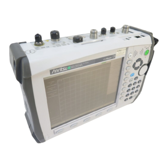
Summary of Contents for Anritsu VNA Master MS203 A Series
- Page 1 Maintenance Manual VNA Master Model MS203xA Vector Network Analyzer Anritsu Company P/N: 10580-00168 490 Jarvis Drive Revision: B Morgan Hill, CA 95037-2809 Printed: December 2008 Copyright 2008 Anritsu Company...
- Page 2 Anritsu is not liable for consequential damages. LIMITATION OF WARRANTY The foregoing warranty does not apply to Anritsu connectors that have failed due to normal wear. Also, the warranty does not apply to defects resulting from improper or inadequate maintenance by the Buyer, unauthorized modification or misuse, or operation outside of the environmental specifications of the product.
- Page 3 This product and its manuals may require an Export License or approval by the government of the product country of origin for re-export from your country. Before you export this product or any of its manuals, please contact Anritsu Company to confirm whether or not these items are export-controlled.
- Page 5 Some or all of the following five symbols may or may not be used on all Anritsu equipment. In addition, there may be other labels attached to products that are not shown in the diagrams in this manual.
- Page 6 For Safety Warning Always refer to the operation manual when working near locations at which the alert mark, shown on the left, is attached. If the operation, etc., is performed without heeding the advice in the operation manual, there is a risk of personal injury.
-
Page 7: Table Of Contents
Table of Contents Chapter 1—General Information Introduction ..............1-1 Required Test Equipment for Performance Verification . - Page 8 Removing the LCD and Backlight Driver PCB from the Main PCB..... . 3-6 Replacement ............3-6 Main PCB Real Time Clock (RTC) Battery Removal and Replacement.
-
Page 9: Chapter 1-General Information
Familiarity with the basic operation of the front panel keys is assumed (for example, how to change measurement mode, preset the unit, or the meaning of "soft key"). Refer to the VNA Master user guide (Anritsu part number 10580-00166). Before making any measurement, verify that that all equipment has warmed up for at least Note 30 minutes. -
Page 10: Required Test Equipment For Performance Verification
Power Output to +13 dBm following options : 2A, 4, 22, 15 Power Meter Power Range: –70 to + 20 dBm Anritsu Dual Channel Model ML2438A Power Sensor Frequency: 10 MHz to 18 GHz Anritsu Model MA2442D (quantity 2) Power Range: –67 to +20 dB... -
Page 11: Replaceable Parts
Replaceable Parts Replaceable Parts To ensure that the correct options are provided on the replacement unit when ordering a Main/Spectrum Analyzer PCB Assembly, all options that are installed in your instrument must be declared on the order. The installed options are listed on a label on the top of the MS203xA and can also be viewed in the System/Status display. - Page 12 Replaceable Parts 10580-00168 Revision B MS203xA...
-
Page 13: Chapter 2-Performance Verification
Chapter 2 — Performance Verification Introduction This chapter provides procedures to verify performance, and Appendix A contains blank test records, which should be copied before use. Familiarity with the basic operation of the front panel keys is assumed (for example, how to change measurement mode, preset the unit, or the meaning of "soft key"). -
Page 14: Spectrum Analyzer Verification
This test verifies the Frequency Accuracy of the Spectrum Analyzer. Procedure: 1. Connect the external 10 MHz Reference to the Anritsu MG3692X Synthesized Signal Source. 2. Do not connect the external 10 MHz Reference to the MS203xA. 3. Connect the output of the synthesizer to the Spectrum Analyzer RF In of the MS203xA. - Page 15 Spectrum Analyzer Verification 5. Set the MG3692A or MG3692B output to 1 GHz CW, with an RF output level of –30 dBm. 6. On the MS203xA, press the Amplitude key, and set the Reference Level to –10 dBm. 7. Press the Freq key and set the Center Freq to 1.0 GHz. 8.
-
Page 16: Spectrum Analyzer Internal Reference Frequency Adjustment
Procedure: 1. Connect the external 10 MHz Reference to the Anritsu MG3692A or MG3692B Synthesized Signal Source. Do not connect the external 10 MHz Reference to the MS203xA. 2. Connect the output of the synthesizer to the Spectrum Analyzer RF In of the MS203xA. -
Page 17: Spectrum Analyzer Ssb Phase Noise Verification
This test can be used to verify the single side band phase noise of the MS203xA. Procedure: 1. Connect the external 10 MHz Reference to the Anritsu MG3692A or MG3692B Synthesized Signal Source. 2. Connect the output of the synthesizer to the Spectrum Analyzer RF In connector of the MS203xA. -
Page 18: Spectrum Analyzer Resolution Bandwidth Accuracy
Spectrum Analyzer Verification Spectrum Analyzer Resolution Bandwidth Accuracy This test checks the accuracy of the resolution bandwidth settings. 1. Connect the external 10 MHz Reference to both the MG3692x synthesized Source and to the MS203xA VNA Master. 2. Verify that the mode of the MS203xA is set to Spectrum Analyzer. Preset the unit. 3. -
Page 19: Spectrum Analyzer Absolute Amplitude Accuracy
Spectrum Analyzer Verification Spectrum Analyzer Absolute Amplitude Accuracy The tests in this section verify the level accuracy of the MS203xA Spectrum Analyzer. This test has two parts: • “Amplitude Accuracy Across Frequency Verification” • “50 MHz Amplitude Accuracy Verification” Amplitude Accuracy Across Frequency Verification Amplitude Accuracy Across Frequency Verification Setup Procedure: 1. - Page 20 Spectrum Analyzer Verification ML2438A POWER METER SENSOR B MA2442A 15NNF50-1.5C N241A50 10 dB MG3692A SOURCE ATTENUATOR 34NN50A 34RSN50 ADAPTER ADAPTER Figure 2-3. Test Setup for Amplitude Accuracy Across Frequency Verification Amplitude Accuracy Across Frequency Verification Test Procedure: Table A-6, “Spectrum Analyzer Absolute Amplitude Accuracy Characterization Chart” on page A-4 complete the Amplitude Accuracy Across Frequency Verification test record as follows: 1.
- Page 21 Spectrum Analyzer Verification 15. Repeat Step to Step for the other frequencies in column 1 of the Amplitude Accuracy Across Frequency Verification tables (Table A-7 through Table A-11). 16. Set the MS203xA Atten Lvl to 5 dB and repeat Step to Step 14.
-
Page 22: 50 Mhz Amplitude Accuracy Verification
Spectrum Analyzer Verification 50 MHz Amplitude Accuracy Verification 50 MHz Amplitude Accuracy Verification Setup: 1. Connect both MA2442D power sensors to the Model ML2438A power meter and calibrate the sensors. 2. Set the frequency of the MG3692A or MG3692B to 50 MHz. 3. -
Page 23: Power Meter Verification
Instrument Critical Specification Recommended Manufacturer/Model Synthesized Signal Source Frequency: 0.1 Hz to 20 GHz Anritsu Model MG3692A or MG3692B with Power Output to +13 dBm options: 2A, 4, 22, 15 Power Range: –70 dBm to Power Meter Anritsu Dual Channel Model ML2438A... - Page 24 Power Meter Verification 4. Set the Model ML2438A power meter to display both Channel A and Channel B. Press the Sensor key, the Cal Factor soft key, and then the Freq soft key. Use the keypad to enter the value matching the frequency of MG3692A or MG3692B as the input signal frequency, which sets the power meter to the proper power sensor calibration factor.
-
Page 25: Vector Network Analyzer Functions
Equipment Required for Vector Network Analyzer Functions Instrument Critical Specification Recommended Manufacturer/Model Frequency Counter Frequency: 2 GHz Anritsu Model MF2412B Open/Short Anritsu Model 22N50 Termination (N male) Frequency: DC to 18 GHz Anritsu Model 28N50-2 Return Loss: 40 dB minimum... -
Page 26: System Dynamic Range
Vector Network Analyzer Functions 9. Turn the Lower Limit On and set it to 6.95 dB. Note that the MS203xA rounds off the value on the display to one decimal place (for example, xx.x). 10. Verify that the data display falls between the Limit Lines. 11. - Page 27 Vector Network Analyzer Functions 19. Press Peak Search and record the MARKER 1 readout value into the “Measured Value” column in Table A-22, “VNA System Dynamic Range — MS2034A” Table A-23, “VNA System Dynamic Range — MS2036A” Appendix Procedure 10 MHz to 3.0 GHz: 1.
-
Page 28: Options Verification
Power Output to +13 dBm options: 2A, 4, 22, 15 RF Detector (for Option 5) Frequency: 10 MHz to 20 GHz Anritsu Model 560-7N50B Power Range: –70 dBm to + Power Meter (for Option 5) Anritsu Dual Channel Model ML2438A... - Page 29 • VNA Master External Power Supply, Anritsu Part Number 40-168-R Procedure: 1. Connect the external power supply (Anritsu part number 40-168-R) to the VNA Master. 2. Press the On/Off key to turn on the VNA Master. 3. Press the Shift key, the Preset (1) key, and then the Preset soft key to reset the instrument to the default starting conditions.
-
Page 30: Low Current Test
Options Verification Low Current Test 1. Press the Bias Tee soft key and then the Bias Tee Voltage soft key. Verify that the Bias Tee voltage is set to 12.0 V and that the Current soft key is set to Low. 2. -
Page 31: High Current Test
Procedure: 1. Connect the GPS antenna to the GPS Antenna connector on the MS203xA. If no fixed GPS antenna is available, then the Anritsu 2000-1410 GPS antenna can be used for this Note test. Ensure that the Anritsu 2000-1410 GPS antenna is in a direct line-of-sight relationship to the satellites, or the antenna must be placed outdoors without any obstructions. - Page 32 Options Verification If a GPS fix is acquired by using the Anritsu 2000-1410 antenna outdoors, then bringing the instrument indoors will cause a loss of the satellite tracking. When the loss occurs, a red cross Note appears on the green GPS indicator, and the Reference Source indicator changes to Int Hi Accy.
-
Page 33: Chapter 3-Remove And Replace Instructions
Battery Pack Information The following information relates to the care and handling of the Anritsu 633-44 battery pack and Lithium-Ion batteries in general. • The 633-44 battery pack that is supplied with the MS203xA may need charging before use. Before using... -
Page 34: Battery Pack Removal And Replacement
Battery Pack Information Battery Pack Removal and Replacement This section provides instructions for the removal and replacing the MS203xA battery pack. Many of the procedures in this section are generic, and apply to many similar instruments. Photos and illustrations that are used are representative and may show instruments other than the MS203xA. 1. -
Page 35: Opening The Ms203Xa Case
Ensure that all work is performed at a static-safe work area. Part numbers for all replaceable parts are found Chapter Before opening the case, Anritsu Company strongly recommends that all internally saved files be saved to a PC using the Master Software Tools utility program or be copied to an external CF card on the MS203xA. In the event that the Main PCB needs to be replaced, this will prevent permanent loss of these files. -
Page 36: Removing The Spectrum Analyzer Pcb
Removing the Spectrum Analyzer PCB 6. Stand the unit up in the normal operating position and separate the 2 halves by about 2 inches. Three cables must be disconnected before the 2 halves can be separated: Figure 3-6. Separating the Case 7. -
Page 37: Removing The Vna Module
Removing the VNA Module Removing the VNA Module 1. The VNA module, Main PCB, and LCD are mounted together (in that order) and mounted to the case top cover. To continue with disassembly, the VNA module must first be disconnected from the Main PCB (refer to Figure 3-8). -
Page 38: Removing The Lcd And Backlight Driver Pcb From The Main Pcb
Removing the LCD and Backlight Driver PCB from the Main PCB Removing the LCD and Backlight Driver PCB from the Main PCB 1. Using a tool such as tweezers or a knife blade, gently unplug one end of the 4 cm long LCD digital data cable (wraps around the edge of the Main PCB). -
Page 39: Main Keypad Membrane And Pcb Replacement
Main Keypad Membrane and PCB Replacement Main Keypad Membrane and PCB Replacement This procedure provides instructions for removing and replacing the main keypad (on the right of the LCD) membrane and PCB. All keypad parts can be replaced without opening the MS203xA case. 1. -
Page 40: 3-10 Replacing The Function Key Keypad
Replacing the Function Key Keypad 3-10 Replacing the Function Key Keypad 1. Disconnect the function key flexible switchpad from connector J2 of the keypad PCB by carefully lifting the locking tab on connector J2 to release the flexible switchpad (Figure 3-12). -
Page 41: Function Key Membrane And Switchpad Replacement
Function Key Membrane and Switchpad Replacement 3-11 Function Key Membrane and Switchpad Replacement This procedure provides instructions for replacing the function key membrane and switchpad. All keypad parts can be replaced without opening the MS203xA case. 1. Place the instrument face up on a static protected work surface. 2. - Page 42 Function Key Membrane and Switchpad Replacement 3-10 10580-00168 Revision B MS203xA...
-
Page 43: Chapter 4-Troubleshooting
Turn-on Problems Unit cannot boot-up, no activity occurs when the On/Off key is pressed: 1. Battery may be fully discharged. Use an external charger (Anritsu part number 2000-1374) to charge a completely discharged battery. 2. Battery may be the wrong type. Use only Anritsu approved battery packs. Some non-approved battery packs will fit into the MS203xA, but are electrically incompatible and will not charge correctly. -
Page 44: Battery Pack Charging Problems
2. Spectrum Analyzer PCB has failed. Replace the Main/Spectrum Analyzer assembly. Option 5, Power Monitor, Problems: 1. Verify correct operation of RF detector (for a list of suitable detectors, refer to the User Guide, Anritsu part number 10580-00166). 2. Replace the Option 5 PCB. No recalibration is required. -
Page 45: Appendix A-Test Records
Appendix A — Test Records This appendix provides test records that can be used to record the performance of the Anritsu VNA Master models MS2034A and MS2036A. Anritsu Company recommends that you make a copy of the following test record pages and document the measurements each time a Performance Verification is performed. Continuing to document this process each time it is performed will provide a detailed history of the performance of your instrument. -
Page 46: Spectrum Analyzer Rf Input Vswr
Spectrum Analyzer RF Input VSWR MS203xA Firmware Revision: ________________ Operator: ________________ Date: ______________ Serial Number: ________________ Options: ___________________________________________________ Spectrum Analyzer RF Input VSWR Table A-1. Spectrum Analyzer RF Input VSWR Measured Value Specification 2.0 max Spectrum Analyzer Frequency Accuracy Table A-2. Spectrum Analyzer Frequency Accuracy Frequency Measured Value Specification (typical) -
Page 47: Spectrum Analyzer Resolution Bandwidth Accuracy
Spectrum Analyzer Resolution Bandwidth Accuracy MS203xA Firmware Revision: ________________ Operator: ________________ Date: ______________ Serial Number: ________________ Options: ___________________________________________________ Spectrum Analyzer Resolution Bandwidth Accuracy Table A-4. Spectrum Analyzer Resolution Bandwidth Accuracy RBW Setting Span Measured Value Specification 3 MHz 4.5 MHz Auto 2.7 MHz to 3.3 MHz 1 MHz... -
Page 48: Spectrum Analyzer Absolute Amplitude Accuracy Characterization Chart
Spectrum Analyzer Absolute Amplitude Accuracy Characterization Chart MS203xA Firmware Revision: ________________ Operator: ________________ Date: ______________ Serial Number: ________________ Options: ___________________________________________________ Amplitude Accuracy Across Frequency Verification Spectrum Analyzer Absolute Amplitude Accuracy Characterization Chart This chart is a characterization of the system components which should be completed before any data is recorded in the test records in Table A-7,... -
Page 49: Spectrum Analyzer Absolute Amplitude Accuracy Measured Values
Spectrum Analyzer Absolute Amplitude Accuracy Measured Values MS203xA Firmware Revision: ________________ Operator: ________________ Date: ______________ Serial Number: ________________ Options: ___________________________________________________ Spectrum Analyzer Absolute Amplitude Accuracy Measured Values Measured Values for –30 dBm, 0 dB Attenuation Table A-7. Measured Values for –30 dBm, 0 dB Attenuation Frequency Measured Value Specification... - Page 50 Spectrum Analyzer Absolute Amplitude Accuracy Measured Values MS203xA Firmware Revision: ________________ Operator: ________________ Date: ______________ Serial Number: ________________ Options: ___________________________________________________ SPA Absolute Amplitude Accuracy Measured Values (continued) Measured Values for –30 dBm, 10 dB Attenuation Table A-9. Measured Values for –30 dBm, 10 dB Attenuation Frequency Measured Value Specification...
- Page 51 Spectrum Analyzer Absolute Amplitude Accuracy Measured Values MS203xA Firmware Revision: ________________ Operator: ________________ Date: ______________ Serial Number: ________________ Options: ___________________________________________________ SPA Absolute Amplitude Accuracy Measured Values (continued) Measured Values for –2 dBm, 30 dB Attenuation Table A-11. Measured Values for –2 dBm, 30 dB Attenuation Frequency Measured Value Specification...
-
Page 52: Characterization Chart For 50 Mhz Amplitude Accuracy Verification
Spectrum Analyzer Absolute Amplitude Accuracy Measured Values MS203xA Firmware Revision: ________________ Operator: ________________ Date: ______________ Serial Number: ________________ Options: ___________________________________________________ 50 MHz Amplitude Accuracy Verification Characterization Chart for 50 MHz Amplitude Accuracy Verification Table A-12. Characterization Chart for 50 MHz Amplitude Accuracy Verification Test Power Level at 50 MHz Required Sensor B Reading 0 dBm... -
Page 53: 50 Mhz Amplitude Accuracy Verification
50 MHz Amplitude Accuracy Verification MS203xA Firmware Revision: ________________ Operator: ________________ Date: ______________ Serial Number: ________________ Options: ___________________________________________________ 50 MHz Amplitude Accuracy Verification Table A-13. 50 MHz Amplitude Accuracy Verification Input Power Reference Input Atten. Level Level Level Measured Reading Specification 0 dBm 10 dBm... -
Page 54: Power Meter Measurement Accuracy
Power Meter Measurement Accuracy MS203xA Firmware Revision: ________________ Operator: ________________ Date: ______________ Serial Number: ________________ Options: ___________________________________________________ Power Meter Measurement Accuracy Input Power Level at 50 MHz Table A-14. Characterization Chart for Test Power Level at 50 MHz Test Power Level at 50 MHz Required Sensor B Reading 0 dBm –50 dBm... - Page 55 Power Meter Measurement Accuracy MS203xA Firmware Revision: ________________ Operator: ________________ Date: ______________ Serial Number: ________________ Options: ___________________________________________________ Power Meter Measurement Accuracy (continued) Input Power Level at 7000 MHz Table A-18. Characterization Chart for Test Power Level at 7000 MHz Test Power Level at 7000 MHz Required Sensor B Reading 0 dBm –50 dBm...
-
Page 56: A-10 Vna Frequency Accuracy
VNA Frequency Accuracy MS203xA Firmware Revision: ________________ Operator: ________________ Date: ______________ Serial Number: ________________ Options: ___________________________________________________ A-10 VNA Frequency Accuracy Table A-20. VNA Frequency Accuracy Frequency Reading @ 2.0 GHz Specification ± 50 kHz A-11 VNA Return Loss Accuracy Table A-21. VNA Return Loss Accuracy Parameter Specification Measured Value... -
Page 57: A-12 Vna System Dynamic Range - Ms2034A
VNA System Dynamic Range — MS2034A MS203xA Firmware Revision: ________________ Operator: ________________ Date: ______________ Serial Number: ________________ Options: ___________________________________________________ A-12 VNA System Dynamic Range — MS2034A Table A-22. VNA System Dynamic Range — MS2034A Frequency Specification Measured Value 2 MHz to 10 MHz 70 dB 10 MHz to 3 GHz 80 dB... -
Page 58: Option 31 Gps Receiver Verification - Spectrum Analyzer Frequency Accuracy
Option 31 GPS Receiver Verification - Spectrum Analyzer Frequency Accuracy MS203xA Firmware Revision: ________________ Operator: ________________ Date: ______________ Serial Number: ________________ Options: ___________________________________________________ A-15 Option 31 GPS Receiver Verification - Spectrum Analyzer Frequency Accuracy Table A-25. Option 31 GPS Receiver Verification - Spectrum Analyzer Frequency Accuracy Frequency Measured Value Error... -
Page 59: Appendix B-Test Fixture Schematics
Appendix B — Test Fixture Schematics The following schematic diagrams are provided for those who wish to build their own test fixtures for the Option 10 verification test. The part numbers that are referenced in the schematic diagrams are Anritsu part numbers. - Page 60 10580-00168 Revision B MS203xA...
- Page 62 Anritsu Company 490 Jarvis Drive Printed on Recycled Paper with Vegetable Soybean Oil Ink Morgan Hill, CA 95037-2809 http://www.anritsu.com/...
Need help?
Do you have a question about the VNA Master MS203 A Series and is the answer not in the manual?
Questions and answers