Sign In
Upload
Manuals
Brands
Anritsu Manuals
Measuring Instruments
MS9710C
Anritsu MS9710C Manuals
Manuals and User Guides for Anritsu MS9710C. We have
2
Anritsu MS9710C manuals available for free PDF download: Operation Manual, Service Manual
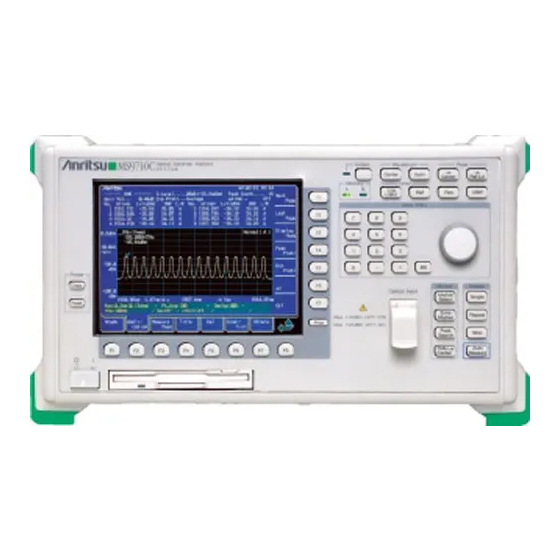
Anritsu MS9710C Operation Manual (269 pages)
Optical Spectrum Analyzer Remote Control
Brand:
Anritsu
| Category:
Measuring Instruments
| Size: 0 MB
Table of Contents
Table of Contents
7
Section 1 Introduction
10
Overview
11
MS9710C Remove Control Functions
11
Interface Port Application Selection Function
11
Examples of Setups Using GPIB/RS-232C
12
Section 2 How to Connect
14
Connecting Devices Using GPIB Cables
15
Setting Interface Conditions for the Connection Port
15
Confirming and Setting the Address
15
Connecting a Device Using an RS-232C Cable
16
RS-232C Interface Signal Connection Diagrams
17
Setting Interface Conditions for the Connection Port
18
Setting RS-232C Interface Conditions
18
Section 3 Standards
20
GPIB Standard
21
RS-232C Standard
21
Device Message List
22
IEEE 488.2 Common Commands and the Commands Supported by the MS9710C
24
Status Messages
25
MS9710C Device Message List
28
Section 4 Initial Setting
40
Initialization of Bus by IFC Statement
43
Initialization of Message Exchange by DCL and SDC Bus Commands
45
Initialization of Devices by ∗RST Command
47
Device States at Power-On
52
Section 5 Listner Input Formats
54
Summary of Listener Input Program Message Syntactical Notation
56
Separator, Terminator, and Space before Header
56
General Format of Program Command Message
58
General Format of Query Message
60
Program Message Functional Elements
61
Terminated Program
61
Message
61
Program Message
64
White Space
64
Program Message Unit
65
Command Message Unit>/<Query Message Unit
66
Command Program Header
67
Query Program Header
70
Program Header Separator
72
Program Data Separator
72
Program Data Format
73
Character Program Data
74
Decimal Numeric Program
75
Data
79
Suffix Program Data
79
Non-Decimal Numeric Program Data
82
String Program Data
83
Arbitrary Block Program
84
Expression Program Data
88
Section 6 Talker Output Format
90
And Talker Output Formats
90
Differences in Syntax between Listener Input Formats and Talker Output Formats
92
Response Message Functional Elements
93
Terminated Response Message
93
Response Message Terminator
94
Response Message
95
Response Message Unit
95
Separator
95
Response Message Unit
96
Response Header
97
Response Data Separator
97
Response Data
99
By Group Function
104
Section 8 Status Structure
120
IEEE 488.2 Standard Status Model
122
Status Byte (STB) Register
124
ESB and MAV Summary Message
124
Device Dependent Summary Message
125
Reading and Clearing the STB Register
126
Enabling the SRQ
129
Standard Event Status Register
131
Definition of Standard Event Status Register Bits
131
Details on Query Errors
132
Reading, Writing, and Clearing the Standard Event Status Register
133
Reading, Writing, and Clearing the Standard Event Status Enable Register
133
Extended Event Status Register
134
Definition of END Event Status Register Bits
135
Definition of ERROR Event Status Register Bits
136
Reading, Writing, and Clearing the Extended Event Status Register
137
Reading, Writing, and Clearing the Extended Event Status Enable Register
137
Queue Model
138
Section 9 Details on Device Messages
140
ALIN [Auto Alignment]
141
ANA [Analysis]
142
ANAR [Spectrum Analysis Result]
145
AP [Application]
146
APR [Application Result]
155
ARED [Acutual Resolution Data]
164
ARES [Actual Resolution]
164
ATT [Optical Attenuater]
164
AUT [Auto Measure]
165
AVS [Sweep Average]
165
AVT [Point Average]
166
BKL [Back Light]
166
BUZ [Buzzer ON/OFF]
167
CNT [Center Wavelength]
167
CPY [Copy]
168
CRCL [Condition Recall]
168
CSAV [Condition Save]
168
DATE [Date Set]
169
DBA [Memory Data A]
169
DBB [Memory Data B]
170
DCA [Data Condition Memory A]
170
DCB [Data Condition Memory B]
171
DEL [FD File Delete]
171
DMA [Memory Data A]
172
DMB [Memory Data B]
173
DMD [Display Mode]
174
DMK [∆ Marker]
175
DPS [Dip Search]
176
DQA [Memory Data A]
177
DQB [Memory Data B]
177
DRG [Dynamicrange Mode]
178
EMK [Marker Off]
178
ERR [Error]
178
ESE1 [Extended Event Status Enable Register1]
179
ESE2 [Extended Event Status Enable Register2]
179
ESE3 [Extended Event Status Enable Register3]
179
ESR1 [Extended Event Status Register1]
180
ESR2 [Extended Event Status Register2]
180
ESR3 [Extended Event Status Register3]
180
FED [Feed]
181
FMT [FD Format]
181
FOPT [FD File Option]
181
GCL [Graph Clear]
182
HEAD [Header]
182
ITM [Interval Time]
182
LCD [Display Color]
183
LLV [Linear Scale]
184
LOFS [Level Offset]
184
LOG [Log Scale]
185
LVS [Level Scale]
185
MDM [Modulation Mode]
185
MKA [Wavelength Marker A]
186
MKB [Wavelength Marker B]
186
MKC [Level Marker C]
187
MKD [Level Marker D]
188
MKV [Marker Value Wavelength/Frequency Select]
189
MOD [Measure Mode]
189
MPT [Sumpling (Measureing) Points]
190
MSL [Memory Select]
190
OPT [Light Output]
190
PKC [Peak → Center]
191
PKL [Peak → Level]
191
PKS [Peak Search]
192
PWR [Power Monitor]
193
RCAL [Resolution Calibration]
193
PWRR [Power Monitor Result]
194
RCL [FD File Recall]
194
RES [Resolution]
195
RLV [Reference Level Scale]
195
SAV [FD File Save]
196
SMT [Smooth]
196
SPC [Spectrum]
196
SPN [Span Wavelength]
197
SRT [Repeat Sweep]
197
SSI [Single Sweep]
197
SST [Sweep Stop]
198
STA [Start Wavelength]
198
STO [Stop Wavelength]
198
TDL [EXT-Trigger Delay Time]
199
TDSP [Time & Date Display On/Off]
199
TER [Title Erase]
199
TIME [Time Set]
200
TLSA [Measure Mode (Adjust to TLS)]
200
TLST [Measure Mode (TLS Tracking)]
201
TMC [TMKR → Center]
201
TMK [Trace Marker]
201
TRM [Terminater]
202
TSL [Trace Select]
203
TTL [Title]
203
VBW [Video Band Width]
204
WCAL [Wavelength Calibration]
204
WDP [Vacuum/Air Set]
205
WOFS [Wavelength Offset]
205
WSS [Setting Wavelength Start and Stop]
206
ZMK [Zone Marker]
206
Precautions on Creating a Program
208
Program Examples
209
Section 11 Labview Measuring Instrument
218
About Labview
219
Installation
219
Program Examples
220
List of Measuring Instrument Drivers
222
Description of Measuring Instrument Driver Functions
226
Common Parameters
226
Description of Functions
227
Appendix A Error Messages
250
A.1 System Errors (000 to 099)
251
A.3 Key Operation Errors (200 to 299)
252
A.4 Device Errors (300 to 499)
254
Appendix B Binary Data Transfer Formats
256
Appendix C Comparison Table of GPIB
258
Commands of Controller
258
Appendix F MS9710C and HP Optical Spectrum
262
Mand Compatibility Table
262
Appendix D Example of Program Used on
264
Appendix E MS9710C and MV02 (MS9703A)
264
Command Compatibility Table
264
Advertisement
Anritsu MS9710C Service Manual (93 pages)
Optical Spectrum Analyzer
Brand:
Anritsu
| Category:
Measuring Instruments
| Size: 1 MB
Table of Contents
About this Manual
7
Table of Contents
8
Section 1 Outline
11
Upgrading Software
12
Installing Optional Light Sources
12
Troubleshooting and Repairing Faults
13
Section 2 Name and Function of each Part
15
Part Names
16
Removing Covers
21
Removing Top Cover
21
Removing Left Side Cover
22
Removing Right Side Cover (See the above Figure.)
22
Removing Right Side Cover
22
Removing Rear-Panel Cover 1
23
Removing Rear-Panel Cover
23
Opening Printer Chassis
24
Removing Bottom Cover
25
Explanation of Modules
26
Control Module (A1 and A13)
26
Motor Drive (A2)
27
Front Panel (A3)
27
Measure CPU and Optical Module (A4 and A6)
27
Control Module (A1 and A13)
27
Interface (A5)
28
Optional White Light Module (A7)
28
Optional Lamp Module (A8)
28
Optional Reference Light Module (A9)
28
Optional Reference Module (A10)
28
Power (A11)
28
Motherboard (A12)
29
Power Unit (E1)
29
Fan (E2)
29
Fdd (E3)
29
Printer Driver (E4)
29
Printer (E5)
29
Lcd (H1)
29
Section 3 Maintenance Mode
31
Role of Maintenance Mode and Start Method
32
Role of Maintenance Mode
32
Starting Maintenance Mode
32
Maintenance Operations
33
Updating Software Version
33
Initializing Backup RAM
34
Initializing Timer
34
Adding Options
35
Setting Equipment Version Display
36
Other Special Functions
36
List of Function Keys
37
Section 4 Installing Optional Light Sources
39
Outline
40
White Light Source
40
Parts
40
Installing
43
Setting
45
Wavelength Reference Light Source
46
Parts
46
Installing
49
Settings
52
Section 5 Troubleshooting
53
General
55
Error Message at Initial Screen
55
Abnormal Data I/O
56
Abnormal Measurement
56
Abnormal Performance
57
Abnormal Light Source Option
57
Section 6 Repair
59
Removing and Testing each Module
60
Control Module
60
Motor Drive Module
61
Panel Module
62
Measure Cpu/Optical Module
64
Interface Module
66
White Light Module (Option)
67
Lamp Module (Option)
68
Reference Light Module (Option)
70
Reference Module (Option)
71
Power Module
73
Motherboard Module
74
Power Unit Module
75
Fan Module
77
FDD Module
77
Printer Driver Module
78
Printer Module
79
LCD Module
80
Exchange of Optical Connector Procedure
82
Factory Repair
86
Appendix A Software Update
87
Appendix B List of Options
89
Advertisement
Related Products
Anritsu ms9710b
Anritsu MS9740A
Anritsu MS9740B
Anritsu VNA Master MS2035B
Anritsu MS46322A-030
Anritsu MS2026A
Anritsu MS2718B
Anritsu MS27200A
Anritsu MS2840A-117
Anritsu VectorStar MS4642A
Anritsu Categories
Measuring Instruments
Test Equipment
Portable Generator
Control Unit
Thermometer
More Anritsu Manuals
Login
Sign In
OR
Sign in with Facebook
Sign in with Google
Upload manual
Upload from disk
Upload from URL