
Related Manuals for Woodward easYgen-300


Summary of Contents for Woodward easYgen-300
- Page 1 37218 easYgen-300 Genset Control Operation Manual Software Version 1.0xxx Manual 37218...
- Page 2 Provides other helpful information that does not fall under the warning or caution categories. Woodward Governor Company reserves the right to update any portion of this publication at any time. Information provided by Woo ward Governor Company is believed to be correct and reliable.
-
Page 3: Table Of Contents
Manual 37218 easYgen-300 Series - Genset Control Revision History Rev. Date Editor Change NEW 04-10-15 Release Content 1. G ..................8 HAPTER ENERAL NFORMATION Related Documents..........................8 Overview ..............................9 300 O .................11 HAPTER ERIES VERVIEW 3. E ............12 HAPTER LECTROSTATIC ISCHARGE WARENESS 4. - Page 4 Manual 37218 easYgen-300 Series - Genset Control 8. F ................... 44 HAPTER UNCTIONAL ESCRIPTION Overview............................... 44 Application Modes ..........................45 Application Mode {1 breaker open/close} – [320], [320X], [350], [350X] ........45 Application Mode {2 breakers open/close} – [350], [350X] ............
- Page 5 Manual 37218 easYgen-300 Series - Genset Control 11. E ....................88 HAPTER VENT OGGER GetEventLog Software ..........................88 Installing GetEventLog........................88 Starting GetEventLog .........................88 Resetting the Event Logger ......................89 12. T ....................90 HAPTER ECHNICAL 13. A ......................92 HAPTER CCURACY A. C ......................93 PPENDIX OMMON Alarm Classes ............................93...
- Page 6 Figure 5-2: Wiring diagram – easYgen320X........................... 16 Figure 5-3: Wiring diagram – easYgen350..........................17 Figure 5-4: Wiring diagram – easYgen350X........................... 18 Figure 6-1: easYgen-300 back view - terminal arrangement ....................19 Figure 6-2: Power supply................................. 20 Figure 6-3: Charging alternator input/output ........................... 20 Figure 6-4: Voltage measuring - generator 3Ph 4W ........................
- Page 7 Manual 37218 easYgen-300 Series - Genset Control Tables Table 1-1: Manual - overview..............................8 Table 2-1: easYgen series 300 product features........................11 Table 4-1: Housing - panel cut-out ............................13 Table 6-1: Power supply - terminal assignment........................20 Table 6-2: Charging alternator input/output - terminal assignment ..................20 Table 6-3: Voltage measuring principles ..........................
-
Page 8: Chapter 1. General Information
Manual 37218 easYgen-300 Series - Genset Control Chapter 1. General Information Related Documents ≡≡≡≡≡≡≡≡≡≡≡≡≡≡≡≡≡≡≡≡≡≡≡≡≡ Type English German easYgen-300 Series easYgen-300 – Manual this manual 37218 GR37218 Additional Manuals LeoPC1 – User Manual 37146 GR37146 PC program for configuration, parameter visualization, remote control, data logging, language upload, alarm and user management, and event recorder management. -
Page 9: Overview
Manual 37218 easYgen-300 Series - Genset Control Overview ≡≡≡≡≡≡≡≡≡≡≡≡≡≡≡≡≡≡≡≡≡≡≡≡≡ Figure 1-2: Functional overview © Woodward Page 9/114... - Page 10 Manual 37218 easYgen-300 Series - Genset Control The easYgen-300 Series generator set control ler provides the following funct ions: • Gen-set control • Engine and gen erator protection • Engine data measurement - including oil pressure and temperature, coolant temperature, battery voltage, speed, service hours, etc.
-
Page 11: Easygen Series 300 Overview
Table 2-1: easYgen series 300 product features NOTE So e parameters of the easYgen-300 series can only be configured using the Direct Configuration Ca- ble D PC (P/N 5417-557) and a notebook/PC with the software LeoPC1. These parameters are indicated... -
Page 12: Chapter 3. Electrostatic Discharge Awareness
To prevent damage to elect ronic comp onents caused by imprope r handlin g, rea d and obs erve the pre- cautions in Woodward manual 82715, Guide for Handling tection of Electro nic Controls , Printed Circuit Boards, and Module Page 12/114... -
Page 13: Chapter 4. Housing
Manual 37218 easYgen-300 Series - Genset Control Chapter 4. Housing Dimensions / Panel Cut-Out ≡≡≡≡≡≡≡≡≡≡≡≡≡≡≡≡≡≡≡≡≡≡≡≡≡ Figure 4-1: Housing - panel cut- Description Dimensi Tolerance Height Total 158 mm Panel cut-out 138 mm + 1.0 mm Housing dimension 136 mm Width... -
Page 14: Installation
Manual 37218 easYgen-300 Series - Genset Control Installation ≡≡≡≡≡≡≡≡≡≡≡≡≡≡≡≡≡≡≡≡≡≡≡≡≡ For installation into a door panel, proceed as follows: Panel cut-out Cut out the panel according to the dimensions in Figure 4-1. Remove terminals Loosen the wire connection terminal screws on the back of the unit and remove the wire connection terminal strips if required (1). -
Page 15: Chapter 5. Wiring Diagrams
Free programmable (relay 4) Fuel relay (relay 5) Crank (relay 6) Engine D+, 24 Vdc (charge alternator) D+, 12 Vdc (charge alternator) Subject to technical mocifications. 2004-09-21 | easYgen-300 Wiring Diagram eYg300ww-0439-ap.skf Figure 5-1: Wiring diagram – easYgen 320 © Woodward Page 15/114... -
Page 16: Figure 5-2: Wiring Diagram - Easygen320X
Crank (relay 6) Engine D+, 24 Vdc (charge alternator) D+, 12 Vdc (charge alternator) MPU + MPU - CAN-L CAN-H Subject to technical mocifications. 2004-09-21 | easYgen-300 Wiring Diagram eYg300ww-0439-ap.skf Figure 5-2: Wiring diagram – easYgen320X Page 16/114 © Woodward... -
Page 17: Figure 5-3: Wiring Diagram - Easygen350
Free programmable (relay 4) Fuel relay (relay 5) Crank (relay 6) Engine D+, 24 Vdc (charge alternator) D+, 12 Vdc (charge alternator) Subject to technical mocifications. 2004-09-21 | easYgen-300 Wiring Diagram eYg300ww-0439-ap.skf Figure 5-3: Wiring diagram – easYgen350 © Woodward Page 17/114... -
Page 18: Figure 5-4: Wiring Diagram - Easygen350X
Crank (relay 6) Engine D+, 24 Vdc (charge alternator) D+, 12 Vdc (charge alternator) MPU + MPU - CAN-L CAN-H Subject to technical mocifications. 2004-09-21 | easYgen-300 Wiring Diagram eYg300ww-0439-ap.skf Figure 5-4: Wiring diagram – easYgen350X Page 18/114 © Woodward... -
Page 19: Chapter 6. Connections
Manual 37218 easYgen-300 Series - Genset Control Chapter 6. Connections Terminal Arrangement ≡≡≡≡≡≡≡≡≡≡≡≡≡≡≡≡≡≡≡≡≡≡≡≡≡ 20 19 upper terminal strip configuration plug only [320X], [350X] lower terminal strip 21 22 35 36 Figure 6-1: ea sYgen-300 back view - terminal arrangement © Woodward... -
Page 20: Power Supply
Manual 37218 easYgen-300 Series - Genset Control Power supply ≡≡≡≡≡≡≡≡≡≡≡≡≡≡≡≡≡≡≡≡≡≡≡≡≡ 6.5 to 32.0 Vdc 6.5 to 32.0 Vdc Power supply 0 Vdc Figure 6-2: Power supply Terminal Description 0 Vdc reference potential 2.5 mm² 6.5 to 32.0 Vdc 2.5 mm²... -
Page 21: Voltage Measuring
Manual 37218 easYgen-300 Series - Genset Control ltage Measuring ≡≡≡≡≡≡≡≡≡≡≡≡≡≡≡≡≡ ≡≡≡≡≡≡≡≡ The easYgen 300 series allows the use of different voltage measuring methods for generator and mains voltage depending on the model. These are described in the following text. Measuring... -
Page 22: Voltage Measuring: Generator
Manual 37218 easYgen-300 Series - Genset Control Voltage Measuring: Generator Voltage Measuring: Generator 3Ph 4W, [320X], [350X] Generator voltage 3Ph 4W easYgen 320X & 350X Figure 6-4: Voltage measuring - generato r 3Ph Voltage Measuring: Generator h 3W [320X], [350X] Generator voltage 3Ph 3W easYgen 320X &... -
Page 23: Figure 6-7: Voltage Measuring - Generator 1Ph 2W
Manual 37218 easYgen-300 Series - Genset Control Voltage Measuring: Generator 1Ph 2W, [320], [320X], [350], [350X] Generator voltage 1Ph 2W eYg 320, 320X, 350 & 350X Figure 6-7: Voltage measuring - generator 1Ph 2W Terminal Description Generator voltage - phase L3 480 Vac 2.5 mm²... -
Page 24: Voltage Measuring: Mains, [350], [350X]
Manual 37218 easYgen-300 Series - Genset Control Voltage Measuring: Mains, [350], [35 Voltage Measuring: Mains 3Ph 4W Mains voltage 3Ph 4W easYgen 350 & 350X Figure 6-8: Voltage measuring - mains 3Ph 4W Voltage Measuring: Mains 3Ph 3W, [350X] Mains voltage 3Ph 3W... -
Page 25: Figure 6-11: Voltage Measuring - Mains 1Ph 2W
Manual 37218 easYgen-300 Series - Genset Control Voltage Measuring: Mains 1Ph 2W, [350X] Mains voltage 1Ph 2W easYgen 350X Figure 6-11: Voltage m easuring - mains 1Ph 2W Terminal Description Mains voltage - phase L3 480 Vac 2.5 mm² Mains voltage - phase L2 480 Vac 2.5 mm²... -
Page 26: Mpu (Pickup) [320X], [350X]
Manual 37218 easYgen-300 Series - Genset Control MPU ( pickup) [320X], [3 50X] ≡≡≡≡≡≡≡≡≡≡≡≡≡≡≡≡≡≡≡≡≡≡≡≡≡ Rotating shaft Sensor Pickup input Figure 6-12: MPU - principle overview Shield 24 V Pickup input < 1,0 V Figure 6-13: MPU input Terminal Description inductive/switching 2.5 mm²... -
Page 27: Discrete Inputs
Manual 37218 easYgen-300 Series - Genset Control Discrete Inputs ≡≡≡≡≡≡≡≡≡≡≡≡≡≡≡≡≡≡≡≡≡≡≡≡≡ Discrete Inputs: Bipolar Signals The discrete inputs are galvanically isolated allowing for a bipolar connection. The discrete inputs are able to handle positive or negative signals. NOTE All discrete inputs must use the same polarity, either positive or negative signals, due to the common ground. -
Page 28: Discrete Inputs: Operation Logic
Manual 37218 easYgen-300 Series - Genset Control Discrete Inputs: Negative Signal 6.5 to 32.0 Vdc Discrete input 1 Discrete input 2 Discrete input 3 Discrete input 4 Discrete input 5 Figure 6-16: Discrete inputs - alarm/control input - negative signal Description Term. -
Page 29: Relay Outputs
Manual 37218 easYgen-300 Series - Genset Control Relay Outputs ≡≡≡≡≡≡≡≡≡≡≡≡≡≡≡≡≡≡≡≡≡≡≡≡≡ The easYgen series 300 provides up to six (6) galvanically isolated relay outputs. Some relay outputs have fixed assignments an d cannot be configured. max. 250 Vac/dc Relay output external device... -
Page 30: Interfaces
2/7 Table 6-11: Interfaces - connection overview NOTE The DP C cable (P/N 5417-557) is intended for service operation only. Do not operate the easYgen-300 with the DPC plugged into the unit during regular operation. Page 30/114 © Woodward... -
Page 31: Can Bus - [320X], [350X]
Manual 37218 easYgen-300 Series - Genset Control CAN Bus - [320X], [350X] Wiring CAN-L CAN bus CAN-H Figure 6-20: Interfaces - CAN bus Terminal Description CAN-L 2.5 mm² CAN bus CAN-H 2.5 mm² Shielding Shield CAN-H Interface CAN-L CAN bus 0.01 uF... -
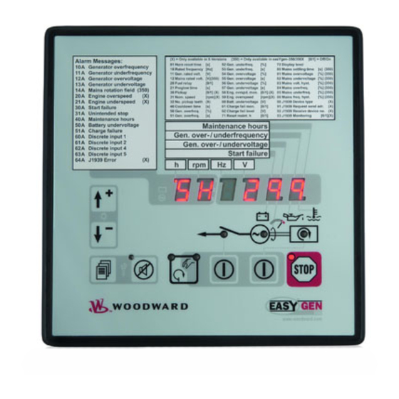
Page 32: Chapter 7. Operation And Navigation
Manual 37218 easYgen-300 Series - Genset Control Chapter 7. Operation and Navigation Figure 7-1: Front panel and display igure 7-1 illustrates the front panel/display which includes push-buttons, LEDs and the alphanumerical 7 seg- LED display. A short description of the front panel is given below. -
Page 33: Operation And Display
Manual 37218 easYgen-300 Series - Genset Control Operation and Display ≡≡≡≡≡≡≡≡≡≡≡≡≡≡≡≡≡≡≡≡≡≡≡≡≡ Purpose of the Status LEDs The easYgen has several status LEDs to indicate the operating state. The LEDs indicate the following conditions Mains voltage present (only easYgen 350 and 350X) -
Page 34: Configuring The Easygen
Refer to Alarm Messages on page 38 for th e description o the alarm messages. For customization of your easYgen-300 front using the paper strips, refer to Front Customization on page 97. Page 34/114 © Woodward... -
Page 35: Cycling Through The Displayed Operating Values
Manual 37218 easYgen-300 Series - Genset Control Cycling Thr ough the Displayed Operating Values If the easYgen is in normal o peration, the operator may advance through the different operatin g parameters u the Scroll button . The p arameters are displayed in the order shown below (some param... -
Page 36: Table 7-1: Display Of Operating Values
Manual 37218 easYgen-300 Series - Genset Control Parameter Display Applies to Mains voltage easYgen 350X Average of the phase-phase easYgen 350 voltages (two of the three easYgen 320X phase indicators are displayed easYgen 320 alternately) Mains voltage easYgen 350X (phase voltage) -
Page 37: J1939 Visualization [320X], [350X]
Manual 37218 easYgen-300 Series - Genset Control J1939 Visualization [320X], [350X] The easYgen 300 with th e X package is able to display standard J1939 messages, which are se t by the engi control to the easYgen via the CAN bus. The values are displayed on the unit and in LeoPC1. -
Page 38: Alarm Messages
65270 Table 7-2: J 1 939 me ssag In case of a defective s sor or a broken wire the easYgen-300 displays four dashes instead of the J193 9 value follo wing the re spective J1939 identifier. Figure 7-3: J1939... -
Page 39: Figure 7-4: Additional Alarm Display
Manual 37218 easYgen-300 Series - Genset Control Figure 7-4 shows t e additional alarm sta tes using the vertical segments of the last two digits of the seven- ent splay . The four top segmen are pre-assigned with the alarms shown in Figure 7-4, but are freely configurable via LeoPC1 for common alarms from a list of alarms located in Table 7-4. -
Page 40: Table 7-4: Alarm Messages
Manual 37218 easYgen-300 Series - Genset Control Alarm Alarm class Display Applies to 21 Engine underspeed F: Shutd 350X 320X 30 Start fail F: Shutdown 350X 320X 31 Unintended stop F: Shutdow 350X 320X 40 Maintenance hours B: Alarm 350X... -
Page 41: Configuration Displays
Manual 37218 easYgen-300 Series - Genset Control nfigurati on D isplays following param eters can be configured as de scribed under Configuring the easYgen on page 34: Parameter Range Display Applies to Time until horn 0 to 1000 s 350X... - Page 42 Manual 37218 easYgen-300 Series - Genset Control Parameter Range Display Applies to Generator un- 50.0 to 130.0 % 350X derfrequency [0.1 % interval] threshold 320X Generator 0.1 to 99.9 s 350X underfrequency [0.1 s interval] delay time 320X Generator ov 50.0 to 125.0 %...
-
Page 43: Table 7-5: Configuration Displays
Manual 37218 easYgen-300 Series - Genset Control Parameter Range Disp Applies to Display level 1, 2, 3 350X 320X Mains settling 0 to 9999 s 350X time [1 s interval] 320X Mains over- 50.0 to 1 30.0 % 350X voltage thresh- [0.1 % in... -
Page 44: Chapter 8. Functional Description
Manual 37218 easYgen-300 Series - Genset Control Chapter 8. Functional Description Overview ≡≡≡≡≡≡≡≡≡≡≡≡≡≡≡≡≡≡≡≡≡≡≡≡≡ Applica tion mode {1 breaker open/close} {2 breakers ope n/close } easYgen Version [320], [320X], [350], [350X] [350], [350X Operation Mode AUTO AUTO Operate the engine • Start engine by:... -
Page 45: Application Modes
Manual 37218 easYgen-300 Series - Genset Control Application Modes ≡≡≡≡≡≡≡≡≡≡≡≡≡≡≡≡≡≡≡≡≡≡≡≡≡ The most important features of th e application modes are illustrated in the following. Please note that the 2 reaker application mode is only possible with the easYgen versions [350], and [350X]. -
Page 46: Operating Modes
Manual 37218 easYgen-300 Series - Genset Control Operating Modes ≡≡≡≡≡≡≡≡≡≡≡≡≡≡≡≡≡≡≡≡≡≡≡≡≡ perating Mode STOP NOTE Selecting th e operating mode STOP is not the same as an EMERGENCY STOP. In some cases the easYgen wi ll perform additional logic functions, such as an engine cool down period, before the en- gine is stop ped. -
Page 47: Operating Mode Manual
Manual 37218 easYgen-300 Series - Genset Control Oper ating Mode MANUAL You find an overview about the butt ons, LEDs and the seven-segment dis play under Operation and igation on page 32. In the MANUAL operating mode (AUTO - MANUAL button... - Page 48 Manual 37218 easYgen-300 Series - Genset Control CB close sequence: Action Breaker control Press t he BREAKER CONTROL button Operati Open GCB The G CB close relay (relay 2) de-energizes to open the GCB – LED goes o Delay Breaker dela...
- Page 49 Manual 37218 easYgen-300 Series - Genset Control Engine start sequence: Action START Press the START - STOP button Delay Preglow time If diesel start logic is selected the relay will energize the glow plugs for the tim configured in the en...
- Page 50 Manual 37218 easYgen-300 Series - Genset Control Application Mode {1 breaker open/close} – [320], [320X], [350], [350X] The START - STOP button Starts the engine (if the engine is stopped, LED is not illuminated) Stops the engine (if the engine is running, LED...
-
Page 51: Automatic
Manual 37218 easYgen-300 Series - Genset Control Operating Mode AUTOMATIC In the A UTOMATIC op rating mode, all engine, GCB, and/or MCB functions are operated via the discrete inputs or automa tically by the control unit ( . a mains failur e). - Page 52 Manual 37218 easYgen-300 Series - Genset Control Detailed operation with 2 CBs in automatic mode (mains are not present) - [350], [350X] Preconditions: • Generator is stopped – LED is not illuminated • MCB is closed – LED is illuminated •...
- Page 53 Manual 37218 easYgen-300 Series - Genset Control AMF / Auto Mains Failure Operation - [350], [350X] The operation sequenc e for an AMF operation is similar to the above sequence with the differ ence that a remote start signal is not required for the engin e start and the engine monitoring delay time is not cons idered, i.e.
-
Page 54: Breaker Closure Limits
Manual 37218 easYgen-300 Series - Genset Control Detailed op eration with 1 CB in Automatic mode Preconditions: • Generator is stopped – LED is not illuminated • Unit is in Automatic mode – LED is illuminated Start sequence: Action Remote start... -
Page 55: Functional Description Of The Oil Pressure Input Di1
Manual 37218 easYgen-300 Series - Genset Control Functional Description of the Oil Pressure Input DI1 ≡ ≡≡≡≡≡≡≡≡≡≡≡≡≡≡≡≡≡≡≡≡≡≡≡≡≡≡≡≡≡≡≡≡≡≡≡≡≡≡≡≡≡≡≡≡≡ The easYgen 300 series is provided with an input for oil pressure. The function of this discrete input is described in the following. -
Page 56: Firing Speed Detection
Manual 37218 easYgen-300 Series - Genset Control Firing Speed Detection ≡≡≡≡≡≡≡≡≡≡≡≡≡≡≡≡≡≡≡≡≡≡≡≡≡≡≡≡≡≡≡≡≡≡≡≡≡≡≡≡≡≡≡≡≡ The firing speed is used for crank termination if the parameter "Crank termination by DI1" is not ena bled (refer Parameter "Crank termination by DI1" on page 55 if this parameter is enabled). When "Crank termination by DI1"... -
Page 57: Functional Description Of The Charging Alternator Input/Output
Manual 37218 easYgen-300 Series - Genset Control Functional Description of the Charging Alternator Input/Output ≡≡≡≡≡≡≡≡≡≡≡≡≡≡≡≡≡≡≡≡≡≡≡≡≡≡≡≡≡≡≡≡≡≡≡≡≡≡≡≡≡≡≡≡≡ The easYgen 300 series monitors the charging alternator operation with the following functionality. If the engine is started, the internal switch is closed simultaneously with the crank relay output, and the battery voltage is applied to the exciter winding D+ through the internal switch contacts. -
Page 58: Functional Description Of The 2 Nd Cb Close Delay Time
Functional Description of the 2 CB Close Delay Time ≡≡≡≡≡≡≡≡≡≡≡≡≡≡≡≡≡≡≡≡≡≡≡≡≡≡≡≡≡≡≡≡≡≡≡≡≡≡≡≡≡≡≡≡≡ The easYgen-300 series provides Delayed close GCB and Delayed close MCB (only [350], [350X]) signals in the list of configurable parameters (find more details about this under Relay Outputs on page 83) in order to meet... -
Page 59: Functional Description Of The Engine Released Signal
Manual 37218 easYgen-300 Series - Genset Control Functional Description of the Engine Released Signal ≡≡≡≡≡≡≡≡≡≡≡≡≡≡≡≡≡≡≡≡≡≡≡≡≡≡≡≡≡≡≡≡≡≡≡≡≡≡≡≡≡≡≡≡≡ The easYgen 300 series provides the engine released signal in the list of configurable parameters (find more de- tails about this under Relay Outputs on page 83). It is possible to use this signal for some special applications. Its functionality is described in the foll owing for an emergency power supply. -
Page 60: Chapter 9. Configuration
Manual 37218 easYgen-300 Series - Genset Control Chapter 9. Configuration Restoring Default Values ≡≡≡≡≡≡≡≡≡≡≡≡≡≡≡≡≡≡≡≡≡≡≡≡≡ he easYgen can be reset to factory settings easily. This may be comfortable for configuring the easYgen from nown state. NOTE The unit has to be in... -
Page 61: Configuration Using The Pc
If an extension of the data connection line is required, only the serial cable between DPC and notebook/PC may be extended. NOTE Unplug the DPC after configuration to ensure a safe operation! If the DPC remains plugged into the easYgen-300 unit, a safe operation of the unit can not be guaranteed. © Woodward Page 61/114... -
Page 62: Editing The Configuration File
Configuring the Flags ≡≡≡≡≡≡≡≡≡≡≡≡≡≡≡≡≡≡≡≡≡≡≡≡≡ The easYgen-300 series provides four configurable LED flags in the alphanumerical display to indicate alarms. One or more alarm messages can be assigned to each one of these flags (i.e. the respective flag will be illumi- nated if the configured alarm state(s) occur(s) in addition to the regular alarm indication). -
Page 63: Figure 9-2: Flag Configuration Default
Manual 37218 easYgen-300 Series - Genset Control The flag parameters are displayed in LeoPC 1 (refer to Configuration U sing the PC on page 61 and the LeoPC1 user manual 37146 for more information) un der System – Codes like sh own in Figure 9-2 in default state (alarm "Start fail"... -
Page 64: Chapter 10. Parameters
Manual 37218 easYgen-300 Series - Genset Control Chapter 10. Parameters llowing description o parameters is expanded to include all parameters that are acces sible through LeoPC. ll p ra me rs re a a ess ble via the front panel. -
Page 65: Measuring
Manual 37218 easYgen-300 Series - Genset Control Measuring ≡≡≡≡≡≡≡≡≡≡≡≡≡≡≡≡≡≡≡≡≡≡≡≡≡ Rated system frequency 50/60 Hz Rated system frequency Nennfrequenz im System The rated frequency of the system has to be configured here. [320] [320X] [350] [350X] The generator frequency monitoring as well as the mains failure limits refer to the value configured in this parameter. -
Page 66: Application
Manual 37218 easYgen-300 Series - Genset Control Application ≡≡≡≡≡≡≡≡≡≡≡≡≡≡≡≡≡≡≡≡≡≡≡≡≡ Ignore CB reply YES/NO Ignore CB reply Ignoriere Rückmeldung LS This param eter controls the function of the discrete input s DI4 and DI5. [320] [320X] [350] [350X] YES ..... The discrete inputs DI4 and DI5 are freely configurable. The pa- rameters of the discrete inputs can be accessed and configured via LeoPC1. -
Page 67: Engine
Manual 37218 easYgen-300 Series - Genset Control Engine ≡≡≡≡≡≡≡≡≡≡≡≡≡≡≡≡≡≡≡≡≡≡≡≡≡ Engine: Diesel Fuel relay close to stop / open to stop Fuel relay: close to stop Kraftstoffmagnet: Stopmag. close to stop .To stop the engine the stop solenoid is energized. Once sp... -
Page 68: Engine: Start/Stop Automatic
Manual 37218 easYgen-300 Series - Genset Control Engine: Start/Stop Automatic tarter time 1 to 10 s Starter time Einrückzeit Anlasser The maximum time during which the crank relay remains enabled. The starter re- [320] [320X] [350] [350X] lay de-energizes when the engine reaches ignition speed or the configured time expires. -
Page 69: Breaker
Manual 37218 easYgen-300 Series - Genset Control Breaker ≡≡≡≡≡≡≡≡≡≡≡≡≡≡≡≡≡≡≡≡≡≡≡≡≡ Transfer time GCB/M 0 to 99.99 s Transfer time GCBMCB Pasuenzeit GLSNLS Switching from generator supply to mains supply or from mains supply to gen- [320] [320X] [350] [350X] erator supply occurs automatically depending on the operating conditions. The time between the reply "power circuit breaker is open"... -
Page 70: Monitoring
Manual 37218 easYgen-300 Series - Genset Control Monit oring ≡≡≡≡≡≡≡≡≡≡≡≡≡≡≡≡≡≡≡ ≡≡≡≡≡≡ Time until horn reset 0 to 1,000 s Time until horn reset Zeit bis eset The alarm LED flashes and the centralized alarm (horn) is issued when a new B... -
Page 71: Monitoring: Generator Underfrequency
Manual 37218 easYgen-300 Series - Genset Control Monitoring: Generator Underfrequen Generator underfrequency monitoring fixed to ON Monitoring Überwachung The generator underfrequency monitoring is always enabled and cannot be dis- [320] [320X] [350] [350X] abled. Generator underfrequency li 50.0 to 130.0 %... -
Page 72: Monitoring: Generator Overvoltage
Manual 37218 easYgen-300 Series - Genset Control Monitoring: Generator Overvoltage Generator overvoltage monitoring fixed to ON Monitoring Überwachung The generator overvoltage monitoring is always enabled and cannot be disabled. [320] [320X] [350] [350X] Generator overvoltage limit 50.0 to 125.0 %... -
Page 73: Monitoring: Generator Undervoltage
Manual 37218 easYgen-300 Series - Genset Control Monitoring: Genera tor Undervoltage Generator undervoltage monitorin fixed to ON Monitoring Überwachung The generator undervoltage monitoring is always enabled and cannot be disabled. [320] [320X] [350] [350X] Generator undervoltage limit 50.0 to 125.0 %... -
Page 74: Monitoring: Mains
Manual 37218 easYgen-300 Series - Genset Control onitori ng: Mains ains phase rotation monitoring fixed to ON Monitoring Überwachung The mains phase rotation monitoring is always enabled and cannot be disabled. [320] [320X] [350] [350X] Mains phase rotation direction CW / CCW... -
Page 75: Figure 10-1: Voltage/Frequency Hysteresis
Manual 37218 easYgen-300 Series - Genset Control Emergency pow er: voltage hysteresis 0.0 to 50.0 % Voltage hysteresis Spannungshysterese This value refers to the Rated mains voltage (see page 65). [320] [320X] [350] [350X] This value is referred to for mains failure recognition and mains estimation. If the... -
Page 76: Monitoring: Engine Overspeed
Manual 37218 easYgen-300 Series - Genset Control Monitoring: Engine Overspeed Engine overspeed monitoring ON / OFF Monitoring Überwachung ON ....Overspeed monitoring of the engine speed is carried out according [320] [320X] [350] [350X] to the following parameters. OFF ..... No monitoring is carried out. -
Page 77: Monitoring: Engine Underspeed
Manual 37218 easYgen-300 Series - Genset Control Monitoring: Engine Underspee Engine underspeed monitoring fixed to ON Monitoring Überwachung The engine underspeed monitoring is always enabled and cannot be disabled. [320] [320X] [350] [350X] Engine underspeed limit fixed to 1 ,000 RPM... -
Page 78: Monitoring: Engine Start Fail
Manual 37218 easYgen-300 Series - Genset Control Monitoring: Engine Start Fail Engine start fail monitoring fixed to ON Monitoring Überwachung The engine start fail monitoring is always enabled and cannot be disabled. [320] [320X] [350] [350X] Engine number of start attempts... -
Page 79: Monitoring: Battery Undervoltage
Manual 37218 easYgen-300 Series - Genset Control Monitoring: Battery Undervoltage Battery undervoltage monitoring ixed to ON Monitoring Überwachung The battery undervoltage monitoring is always enabled and cannot be disabled. [320] [320X] [350] [350X] Battery undervoltage limit 8.0 to 42.0 V... -
Page 80: Monitoring: Battery Charge Voltage
Manual 37218 easYgen-300 Series - Genset Control Monitoring: Battery Ch arge Voltage Battery charge voltage moni toring ON / OFF Monitoring Überwachung ON ....Battery charge voltage monitoring is carried out according to the [320] [320X] [350] [350X] following parameters. -
Page 81: Monitoring: Interface
It may be possible to configure all classes of alarms in this parameter but only alarm classes B and F are implemented in the easYgen-300 series. Ensure that only class B or F is configured he J1939 interface monitoring s elf acknowledgement... -
Page 82: Discrete Inputs
Discrete Inputs ≡≡≡≡≡≡≡≡≡≡≡≡≡≡≡≡≡≡≡≡≡≡≡≡≡ The easYgen-300 series has 5 discrete inputs (DI1 to DI5). The discrete inputs 1 & 2 are pre-defined as alarm i puts for oil pressure (DI1) and coolant temperature (DI2). The discrete input 3 is a contr ol input for remote start. -
Page 83: Relay Outputs
Manual 37218 easYgen-300 Series - Genset Control lay Outpu ≡≡≡≡≡≡≡≡≡≡≡≡≡≡≡≡≡≡≡≡≡≡≡≡≡ e easYge n 300 series has 6 (or 4 for [320] & [320X]) relay outputs. The relay outputs 3 and 4 can be freely nfig ured with one signal o... -
Page 84: Counter
Manual 37218 easYgen-300 Series - Genset Control Counter ≡≡≡≡≡≡≡≡≡≡≡≡≡≡≡≡≡≡≡≡≡≡≡≡≡ Maintenance hours 0 to 9,999 h Maintenance hours Wartungsintervall Stunden To disabl e the maintenance counter "hours" confi gure "0". [320] [320X] [350] [350X] This parameter defines the remaining hours until the next maintenance call oc- curs. -
Page 85: Interfaces
Manual 37218 easYgen-300 Series - Genset Control Interfaces ≡≡≡≡≡≡≡≡≡≡≡≡≡≡≡≡≡≡≡≡≡≡≡≡≡ CAN Interface CAN baudrate 20/50/100/125/250/500/800/1000 kBd Baudrate Baudrate The CAN bus baudrate is configured here. [320] [320X] [350] [350X] NOTE The bau d rate is the same for all devices connected to the CAN bus regardless of the selected protocol. -
Page 86: System
Manual 37218 easYgen-300 Series - Genset Control System ≡≡≡≡≡≡≡≡≡≡≡≡≡≡≡≡≡≡≡≡≡≡≡≡≡ P arameter Access Level Display level 1 to 3 Display level Anzeigeebene The user may alter the number of configurable parameters that are displayed on [320] [320X] [350] [350X] the control unit front panel when the unit is in configuration mode. By selecting the highest level of access (level 3), all parameters will be displayed. -
Page 87: Versions
Manual 37218 easYgen-300 Series - Genset Control Versions NOTE The following parameters are not configurable. They may be viewed using LeoPC1 for information pur- poses only. Serial number (S/N) display only Serial number Seriennummer This is the serial number of the easYgen and identifies the control clearly. -
Page 88: Chapter 11. Event Logger
Manual 37218 easYgen-300 Series - Genset Control Chapter 11. Event Logger The event logger is a FIFO (First In/First Out) memory for logging alarm events and operation states of the unit. The capacity of the event logger is 15 entries. Additional event messages overwrite the oldest messages. Since the easYgen 300 units do not include a clock module, the operating hours are stored with each event logger entry as the timestamp. -
Page 89: Resetting The Event Logger
Manual 37218 easYgen-300 Series - Genset Control Figure 11-2: GetEventLog – event logger content The 15 latest events are displayed in chronological order and each entry is comp osed like this: "sign";"operating hour";"alarm/stat e" whereas "sign""+" indicates the occurrence and "-" indi... -
Page 90: Chapter 12. Technical Data
Manual 37218 easYgen-300 Series - Genset Control Chapter 12. Technical Data Name plate ----------------------------------------------------------------------------------------------------- Serial number (numerical) Serial number (Barcode) Date of production (YYMM) Item number Item revision number Details Technical data Type Unit name Type Extended description UL sign (Example for a typical name plate) Measuring values, voltages ----------------------------------------------------------------------------- /∆... - Page 91 Manual 37218 easYgen-300 Series - Genset Control Pre-exciter current output D + ----------------------------- ------------------------------------------------- Max. exciter current 12 Vdc (term inal 4) .......... 0.11 Adc 24 Vdc (term inal 3) .......... 0.11 Adc Note: The charging alternator D+ acts as an output for pre-exciting the charging alternator during engine start-up only.
-
Page 92: Chapter 13. Accuracy
Manual 37218 easYgen-300 Series - Genset Control Chapter 13. Accuracy Measuring value Display Accuracy Notes Frequency enerator 15.0 to 85.0 Hz 0.1 % Mains 40.0 to 85.0 Hz 0.1 % Voltage Generator 0 to 600 V Transformer ratio selectable Mains... -
Page 93: Appendix A. Common
Manual 37218 easYgen-300 Series - Genset Control Appendix A. Common Alarm Classes ≡≡≡≡≡≡≡≡≡≡≡≡≡≡≡≡≡≡≡≡≡≡≡≡≡ The easYgen 300 series provides only the alarm classes B & F: Alarm class Visible in the display LED "Alarm" Relay "Close GCB" Shut-down engine Engine blocked until &... -
Page 94: Conversion Factors
Manual 37218 easYgen-300 Series - Genset Control Conversion Factors ≡≡≡≡≡≡≡≡≡≡≡≡≡≡≡≡≡≡≡≡≡≡≡≡≡ Conversion factors: Temperature °C °F °F °C ° − ° Valu ° ° ° × ° ° ° Value ° ° Conversion factors: Pressure Value × Value Page 94/114 © Woodward... -
Page 95: Appendix B. J1939 Protocol Descriptions
Manual 37218 easYgen-300 Series - Genset Control Appendix B. J1939 Protocol Descriptions 939 Mea suring Value ≡≡≡≡≡ ≡≡≡≡≡≡≡≡ ≡≡≡≡≡≡≡≡≡ ≡≡≡ These J1939 measuring values are received by the easYgen a d visualized in LeoPC1 using direct configur ation. NOTE The values are displayed on the unit with less accuracy. Refer to J1939 Visualiza tion [320X], [350X] page 37 for more information. -
Page 96: Special Emr Messages
Manual 37218 easYgen-300 Series - Genset Control Special EMR messages Type Message acc. to EMR manual Display in LeoPC1 Engine stop information no stop Engine safety Type 1. Engine safety CAN message engine stop request Type 2: CAN message engine stop request... -
Page 97: Appendix C. Front Customization
Series - Genset Control Appendix C. Front Customization The easYgen-300 series is designed language-independent, but can be customized to your demands using paper strips. The left paper strip is intended for customization and may contain more detailed information about the dis- play. -
Page 98: Appendix D. Troubleshooting
The most common problems and their solutions are described in the troubleshooting table. If problems are encountered between the easYgen-300 and its wiring and the engine or other devices, refer to the respective man uals for solving the prob lem. - Page 99 Manual 37218 easYgen-300 Series - Genset Control Symptom Possible cause Possible solution Verify "Generator Circuit Breaker "Generator Circuit Breaker Measure the voltage between ter- If the circuit breaker is closed, Closed" LED is not lit, al- Closed" signal is miswired.
- Page 100 Manual 37218 easYgen-300 Series - Genset Control Symptom Possible cause Possible solution Verify Alarm "30A - Start fail" oc- Low fuel situation. Check, if enough Fuel is present to Fuel level is above fuel pick- curs. run the engine. up and fuel system is properly...
- Page 101 Manual 37218 easYgen-300 Series - Genset Control Symptom Possible cause Possible solution Verify Alarm "21A - Underspeed" Pickup Sensor is miswired to the Check whether the pickup sensor is The easYgen-300 requires 2 occurs, after engine has fired. easYgen-300. properly wired to terminals 37...
- Page 102 Manual 37218 easYgen-300 Series - Genset Control Symptom Possible cause Possible solution Verify CAN / J1939 Communication The parameter for enabling the Check for setting of Parameter 90 Parameter 90 "J1939 Device does not work. J1939 Communica tion is config- "J1939 Device Ty...
-
Page 103: Appendix E. List Of Parameters
Manual 37218 easYgen-300 Series - Genset Control Appendix E. List of Parameters nit number P/N ___ __________________________ Rev _______________________________ Version easYgen- ______________________________________________________________ Projec _____________________________________________________________________ Serial number S/N ________ _______ Date ______________________________ Parameter Setting range Defa ult va Customer setting MEASURING... - Page 104 Manual 37218 easYgen-300 Series - Genset Control Parameter Setting range Default value Customer setting EMERGENCY POWER (AMF) [350 On/Off ON/OFF [350X] [350] Mains fail delay time 0. 20 to 99.99 s 3.00 s [350X] [350] Mains settling time 0 to...
- Page 105 Manual 37218 easYgen-300 Series - Genset Control Parameter Setting range Default value Customer setting [3x0X] Delayed by engine speed Engine: Underspeed Monitoring [3x0X] Limit 1,000 RPM 1,000 RPM [3x0X] [3x0X] Delay 1. 0 s 1. 0 s [3x0X] Alarm class...
- Page 106 Manual 37218 easYgen-300 Series - Genset Control Parameter Setting range Default value Customer setting DISCRETE INPUTS Discrete input [DI1] oil pressure DI 1 operation N.C. N.C. DI 1 delay 0. s 0. s DI 1 alarm class DI 1 delayed by eng. speed...
- Page 107 Manual 37218 easYgen-300 Series - Genset Control Parameter Setting range Default value Customer setting SYSTEM Passwords Display level 1 to 3 Flag 1 gen. overfreq. 1 YES/NO Flag 1 gen. underfreq. 1 YES/NO Flag 1 gen. overvolt. 1 YES/NO Flag 1 gen. undervolt. 1 YES/NO Flag 1 mains rot.
- Page 108 Manual 37218 easYgen-300 Series - Genset Control Parameter Setting range Default value Customer setting SYSTEM Flag 3 gen. overfreq. 1 YES/NO Flag 3 gen. underfreq. 1 YES/NO Flag 3 gen. overvolt. 1 YES/NO Flag 3 gen. undervolt. 1 YES/NO Flag 3 mains rot. field alarm...
-
Page 109: Appendix F. Service Options
Product and Service Warranty (5-01-1205) that is in effect at the time the product is purchased from Woodward or the service is performed. If you are experiencing problems with installation or unsatisfactory per- formance of an installed system, the following options are available: •... -
Page 110: Packing A Control
Stuttgart [+49 (0) 711 789 54-0]. They will help expedite the processing of your order through our distributors or cal service facility. To expedite the repair process, contact Woodward in advance to obtain a Return Authoriza- tion Number, and arrange for issue of a purchase order for the unit(s) to be repaired. No work can be started until a purchase order is received. -
Page 111: How To Contact Woodward
+49 (0) 711 789 54-100 eMail: sales-stuttgart@woodward.com For assistance outside Germany, call one of the following international Woodward facilities to obtain the address and phone number of the facility nearest your location where you will be able to get information and service. Facility... -
Page 112: Engineering Services
Service engineering on-site support is available, depending on the product and location, from our facility Colorado, or from one of many worldwide Woodward offices or authorized distributors. Field engineers are experienced on both Woodward prod... -
Page 113: Technical Assistance
Manual 37218 easYgen-300 Series - Genset Control Technical Assistance ≡≡≡≡≡≡≡≡≡≡≡≡≡≡≡≡≡≡≡≡≡≡≡≡≡ you need to telephone for technical assistance, you will need to provide the following information. Please write down here before phoning: Contact our company ___________________________________________________ our name ______________________________________________________ hone number ____________________________________________________... - Page 114 Phone +49 (0) 711 789 54-0 • Fax +49 (0) 711 789 54-100 sales-stuttgart@woodward.com Homepage http://www.woodward.com/smart-power Woodward has company-owned plants, subsidiaries, and branches, as well as authorized distributors and other authorized service and sales facilities throughout the world. Complete address/phone/fax/e-mail information for all locations is available on our website (www.woodward.com).
Need help?
Do you have a question about the easYgen-300 and is the answer not in the manual?
Questions and answers