Table of Contents
Advertisement
Quick Links
Advertisement
Table of Contents

Related Manuals for Plockmatic BLM 35


Summary of Contents for Plockmatic BLM 35
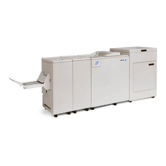
- Page 1 Plockmatic BLM 35/50 Production Booklet Maker Operator Manual Please read this manual carefully before you use this product and keep it handy for future reference. For safety, please follow the instructions in this manual. Doc no: X04107E Date: 26 June 2017...
- Page 2 Electromagnetic compliance This product complies with EU Standard EN 55032:2015, Class A. Operation of this equipment in a residential environment could cause radio interference. NOTE: The domestic environment is an environment where the use of broadcast radio and television receivers may be expected within a distance of 10m of the apparatus concerned.
- Page 3 Introduction This manual contains instructions on the operation and maintenance of this machine. To get maximum versatility from this machine all operators should carefully read and follow the instructions in this manual. Keep this manual in a handy place near the machine. Please read the Safety Information before using this machine.
- Page 4 Safety Information When using this machine, following safety precautions should always be followed. Safety during operation WARNING • To avoid hazardous situations like for instance electric shock or danger while exposed to moving, rotating or cutting devices, do not remove any covers, guards or screws other than those specified in this manual.
- Page 5 General safety, continued CAUTION • The machine and its peripherals must be installed and maintained by a customer service representative who has completed the training course on those models. • Always follow all warnings marked on, or supplied with, the equipment. •...
- Page 6 Page intentionally blank.
-
Page 7: Table Of Contents
TABLE OF CONTENTS What You Can Do With This Machine ................11 Guide to Components ...................... 13 Booklet Maker ..........................13 User Interface ..........................16 Control Panel............................16 Options ..........................19 Rotate Crease Trim Module ......................19 Booklet Maker ..........................24 Alive Logo.............................. - Page 8 BookFold ............................. 48 General..............................48 Selecting BookFold pressure setting ..................... 49 Crease ............................50 Crease Mode ............................50 Crease position ............................. 50 Fine-tuning booklet appearance ..................51 Set registration (fine adjustment) ......................51 Bleed Trimmer - Asymmetric Side Trim ....................52 Bleed Trimmer - Cover Adjust .......................
- Page 9 Cleaning of creaser tools (2x) ....................... 90 Adjustment of Bleed Trimmer registration angle (parallel cut)............... 91 Adjustment of Creaser registration angle ....................92 Best practices for the BLM 35/50 system............... 93 Limitations of the BLM 35/50 system ................94 8. Specification ................... 97 Machine Specifications ....................
- Page 10 Page intentionally blank.
-
Page 11: What You Can Do With This Machine
Trim Module (option) (option) Booklet Maker The Plockmatic BLM50 or the Plockmatic BLM35 Production Booklet Maker System consists of: Rotate Crease Trim Module (optional), also referred to as the RCT Module or the RCT Cover Feeder Module (optional), also referred to as the Cover Feeder or the CF... - Page 12 continued from previous page The set is then transported further into the Booklet Maker to the folding area where the set is folded into a booklet and delivered out to the belt stacker or a downstream module. After the Booklet Maker, an optional BookFold Module can be attached. The stapled and folded books will be fed into the BookFold Module where the spine of the booklets are flattened square.
-
Page 13: Guide To Components
Guide to Components Booklet Maker Top cover Cover for Hand Feed Latch handle Live Logo, only on 50 sheet option Belt Stacker Belt Stacker Cover Slot for optional Cover Feeder... - Page 14 Booklet Maker, continued Belt Stacker Connector Upstreams Communication Downstreams Communication Power Connection Printer interface NOTE: How to connect cables, plugs and jumpers is described at the end of this manual.
- Page 15 Booklet Maker, continued Parts that are important for setup, adjustments, troubleshooting or maintenance are high- lighted below. Hand feeding paper guides Compiler area Staple cartridges (incl. stapler heads) Main power switch Set thickness sensor Control panel Fold roller guide Staple cartridge ejection lever...
-
Page 16: User Interface
User Interface The Plockmatic BLM50 or BLM35 Production Booklet Maker System is controlled from a panel located on the Booklet Maker. The control panel will allow you to set up, adjust and operate the complete system. An optional “Alive logo” makes the state of system visible from a distance. - Page 17 Guided Start Guided Start is a function that takes you through all the basic settings the Booklet Maker System needs for booklet production in eight easy steps. See “Guided Start” in section 2 “Making Booklets” for details. The Jobs Screen Pressing the [Open Jobs] button in the Start screen opens the Open saved Job screen.
- Page 18 The Please wait screen While the machine sometimes needs time to perform changes in settings, the Please wait screen will be shown. Power save mode When the Booklet Maker System is in a ready state, it will enter power save mode after 20 minutes of inactivity.
-
Page 19: Options
Options Rotate Crease Trim Module Top cover Side door... - Page 20 Rotate Crease Trim Module, continued Connections bracket Exit slot Trim waste transport Waste container Cable protector NOTE How to connect cables, plugs and jumpers is described at the end of this manual.
- Page 21 Rotate Crease Trim Module, continued Parts that are important for setup, adjustments, troubleshooting or maintenance are high- lighted below. Exit section “D” Bleed trimmer circular knives Infeed Section “A” Main switch Counter...
- Page 22 Rotate Crease Trim Module, continued Waste chute(s) Creaser registration adjustment Bleed trimmer registration adjustment Latch handle, slide...
- Page 23 Rotate Crease Trim Module, continued Creaser tools Jam clearance baffle, fine registra- tion, section “C” Jam clearance baffle, coarse regis- tration, section “B” Rotator...
-
Page 24: Booklet Maker
Booklet Maker Alive Logo Alive Logo With a BLM50 upgrade kit installed, the three stripes below the user interface will signal status as follows: Not illuminated - System in power save mode or switched off. Steady blue - System is on and ready. Alternating blue/yellow - Soft stop (staples low, cover low, stacker full, waste bin full). -
Page 25: Cover Feeder
Cover Feeder Parts that are important for setup, adjustments, troubleshooting or maintenance are high- lighted below. Loading capacity mark Front side guide Rear side guide Paper orientation indicator Feed roller assembly Air nozzle (2x) Paper separator pad Jam clearance baffle... -
Page 26: Bookfold Module
BookFold Module Top cover Base Connections Cable protector NOTE: How to connect cables, plugs and jumpers is described at the end of this manual. - Page 27 BookFold Module, continued Parts that are important for setup, adjustments, troubleshooting or maintenance are high- lighted below. NOTE: Upper feed belt on operator side cannot be lifted fully BookFold Module, top view, non operator side upper feed belts lifted up Upper feed belt release latch Lower feed belts Upper feed belts...
-
Page 28: Trimmer
Trimmer Top cover Trim bin Base Connections Cable protector NOTE: How to connect cables, plugs and jumpers is described at the end of this manual. - Page 29 Trimmer, continued Parts that are important for setup, adjustments, troubleshooting or maintenance are high- lighted below. Trimmer, top view Set counter Infeed roller shaft Exit drive lifting lever Trimmer fan Trimmer stop Transport belt Exit drive release Upper trim knife Exit compressing brackets...
-
Page 30: Bst4000-1 Belt Stacker Module
The BST4000-1 High Capacity Belt Stacker Module is an option available for the Plockmatic BLM50 or BLM35 Production Booklet Maker System. The stacker can be configured in a straight line after the booklet maker system or at a 90 degree angle. -
Page 31: Bst4000-1 Principle Of Operation
BST4000-1 Control Panel BST4000-1 Belt Stacker Module, continued Power switch (on/off) Power switch (on/off) Belt speed selector Belt speed selector Run-out button (full speed) Run-out button (full speed) BST4000-1 Principle of Operation The belt is triggered by a signal from the Booklet Maker and will run for a set time. The belt speed can be adjusted in order to optimize the stacking function for various BST4000-1 Principle of Operation materials. - Page 32 Page intentionally blank.
-
Page 33: Basics
1. Basics Turning On / Off the Main Power RCT, Booklet Maker, BookFold Module, Trimmer & BST Module Make sure that the Booklet Maker, RCT module (optional) and BST power cords are plugged into the wall outlet. NOTE: BookFold (optional) and/or Trim (optional) Modules are both powered from the Booklet Maker. -
Page 34: Change Staple Cartridges And Check Stapler
Change staple cartridges and Check Stapler The staple cartridges contains approximately 5000 staples each. Each cartridge includes all wearable parts. The cartridges may need to be removed either for replacement or for jam clearance. Change left/right staple cartridge(s) The Booklet Maker will indicate “Replace left/ right/left and right staple cartridges”... -
Page 35: Check Left/Right Stapler
Check left/right stapler If the Booklet Maker indicates “Check right/left/ right and left stapler”, it means that there is a jam in the indicated stapler. Remove the stapler cartridge as described above. Open the Booklet Maker top cover. Remove either or both staple cartridge(s) as described above. -
Page 36: Emptying The Trim Waste Bin
Emptying the trim waste bin Remove the trim waste bin by lifting it and pulling it out. Trim bin... -
Page 37: Belt Stacker
Setting up Belt Stacker BST4000-1 Belt Stacker The Stacker can be used in either right-angled or in-line configuration with the Booklet Maker. In-line mode is preferred if running heavy and large booklets. Setting up Belt Stacker for right-angled mode Setting up Belt Stacker for Right-Angled Mode Follow these steps to correctly set up the Stacker Move the inner Side Guide [A] as Move the inner Side Guide [A]... -
Page 38: Setting Up Belt Stacker For Straight Mode
Setting up Belt Stacker for Straight Mode Setting up Belt Stacker for straight mode Adjust Side Guides to their Adjust Side Guides to their outermost position by loosening outermost position by loosening knobs [A]. knobs [A]. Adjust the stacking with belt speed selector [B]. -
Page 39: Making Booklets
2. Making Booklets Guided Start Guided Start is a function that takes you through all the basic settings the Booklet Maker System needs to start booklet production in a few easy steps. Customizing settings and fine adjustments are described later in this chapter. Guided Start, step by step Guided Start Press the [Guided Start] button to... - Page 40 Guided Start 3/8 Choose either of two suggested formats (except for B4 which only has one suggested format). When Face Trim is set to Auto, a minimum trim, based on the information from Set Thickness Sensor, is calculated. To set the trim manually, follow “Finished Booklet size”...
- Page 41 Guided Start 7/8 Select whether the booklets should have a creased cover or not. This feature is used to avoid high area coverage toner cracking on the spine on booklets containing less than 6 sheets. Press the corresponding button. After you are done, press the [Finish] button to conclude the Guided Start.
-
Page 42: Changing Settings
Changing settings General procedure Settings can changed in one of two ways. “Temporary”, which means that the changes will remain until a new job is loaded or “Permanent”, which means that the changes will be stored as a job. This job can later be recalled. Procedure for temporary changes: From the Settings for Booklet Production screen, select the option you wish to alter and make your selection. -
Page 43: Auto Sheet Size
AUTO sheet size AUTO means that the Booklet Maker will adjust to the paper size information sent from the printer. Auto Rotate will be turned on and a finished booklet size will be chosen from a predefined list i.e. the [Finished Booklet Size] button will be greyed out. No other settings will be affected. Custom input sheet size From the Input sheet size screen, press any of the Custom size buttons and then press the... -
Page 44: Custom Booklet Size
Custom booklet size To set the trim manually, press [Custom Booklet Size] and then [Edit]. To adjust the amount of face trim, press the number on the [Length] button and type in the desired length of the booklet, decimals included. Also, the [plus] and [minus] buttons can be used to change the numbers. -
Page 45: Customizing Settings
Customizing settings Staple Selecting stapling On or Off From the Settings for Booklet Production screen, press the [Staple] button. Select On or Off by pressing the corresponding button and save setting by pressing the green [check] button. Adjusting staple position From the Settings for Booklet Production screen, press the [Staple] button. -
Page 46: Fold Position
Fold position Adjusting fold position From the Settings for Booklet Production screen, press the [Fold position] button. The position of the fold can be changed up to 3 mm (0.12”) on either side of the center of the set. Press the [+] button move position closer to the lead edge and press the [-] button move position closer to the trail edge. -
Page 47: Cover
Cover From the Settings for Booklet Production screen, press the [Cover] button. Press the [Yes] button and confirm by pressing the green [check] button. Air Separation You may want to increase the Air flow when running thick, heavy covers. From the Cover screen, press the [Air separation] button. -
Page 48: Purge Cover
Purge Cover he Purge mode is used when you want to completely empty the Cover Feeder from covers. Remove all cover sheets from the bin. Press the [Purge Cover] button and confirm by pressing the green [check] button. The pre-fed cover sheet will now be fed into the Booklet Maker to the stapling area, but will not be stapled. -
Page 49: Selecting Bookfold Pressure Setting
The table below shows highest supported BookFold pressure settings on BLM35 and BLM50 Pro- duction Booklet Maker systems. NOTE: The following table indicates maximum BookFold pressure setting that can be used on the Production Booklet Maker systems without slowing the printer down. Number of sheets SRA3 8.5x11"... -
Page 50: Crease
Crease The Crease function makes it possible to crease the cover sheet of the booklet in order to avoid toner cracking or flaking at the fold. Crease Mode From the Settings for Booklet Production screen, press the [Crease] button. Press the corresponding button to choose [On Fine], [On Coarse] or [OFF]. -
Page 51: Fine-Tuning Booklet Appearance
Fine-tuning booklet appearance Set registration (fine adjustment) You can fine-tune the booklet quality by adjust- ing the joggers in the booklet maker. From the Settings for Booklet Production screen, press the [Finished Booklet Size] button. From the Finished Booklet size screen, press the [Set registration (fine adjustment)] button. -
Page 52: Bleed Trimmer - Asymmetric Side Trim
Bleed Trimmer - Asymmetric Side Trim From the Finished Booklet size screen, press the [Asymetric Side Trim] button. Choose Asymmetric Side Trim if you want to offset the bleed trim. Move using the buttons and press the green [check] button to save setting. -
Page 53: Hand-Feeding
Hand-feeding The Booklet maker can be operated in two modes. On-line mode, when used together with the printer, or off-line mode, working as a stand-alone unit. Hand feed mode Setup the Booklet Maker to the correct paper size. Open the Hand Feed Cover [B]. Adjust the hand feeding paper guides [A] to the correct paper size. - Page 54 Page intentionally blank.
-
Page 55: Tools
3. Tools The Tools screen From the Start screen or the Settings for Booklet Production screen, press the [Tools] button to get to the General System Settings screen. Select the setting you want to change by pressing the corresponding button. Press the green [check] button to save your changes. -
Page 56: Software Version
Software version Select module by pressing the corresponding button to display the software version. Press [Exit] button to go back to the Settings screen. Paper path light This function is for service purposes. To turn the paper path light on, press [ON 5 min] button and save by pressing the [OK] button. -
Page 57: Service Mode
Service mode This function is for authorized service personnel only and is password protected. Fold delay With this feature, the set will stay under pres- sure between the fold rollers for an extended time to provide a flatter fold. This only applies to sheet sizes shorter than 400mm or 15.8”... -
Page 58: Auto Rotate
Auto Rotate If your system includes the optional RCT mod- ule, you can select whether you want Auto Rotate function to be ON or OFF by pressing the corresponding button. It is recommended to keep this ON. When turned on, the Rotator will automatically rotate all sheet sizes sent from the printer in long edge feed, enabling higher printer produc- tivity. -
Page 59: Jobs
4. Jobs Handling jobs The Booklet Maker has a maximum storage capacity of 20 different jobs. To make temporary changes in the actual job settings or temporary changes of a stored job, see section 2, “Making Booklets.” From the Start screen, press the [Jobs] button to be able to store, change or delete jobs. Saving a Job To store a job, press from the Settings for... -
Page 60: Opening And Handling Stored Jobs
Opening and handling stored Jobs To access already stored jobs, press from the Start Screen. Open (load) any stored job by pressing the job and confirm by pressing the green [check] mark. Delete any stored job by pressing the job but- ton, the waste bin symbol and then confirm by pressing the [Yes] button. -
Page 61: Clearing Misfeed(S)
5. Clearing Misfeed(s) Clearing misfeed(s) General If a misfeed condition should occur, it is indicated on the Booklet Maker display. The message “Clear Misfeed(s)”, an error code and the location of the misfeed is displayed. See examples below. Misfeeds in the Rotate Crease Trim Module are indicated by the error code RCT-XXX. -
Page 62: Rct Module
RCT Module Clearing misfeed(s) Infeed “A” area and exit “D” area Open the RCT top cover. Lift up baffles “A” and “D” if needed. Remove any misfeed(s). Lower baffles “A” and “D” to normal position Misfeed(s) in the trimmer area are rolled out by rotating the rubber surfaced pinch roller [A]. -
Page 63: Registration And Creaser Area
Registration and creaser area Open the slide door [A]. Unlatch and pull out the slide [B]. Open baffles “B” and “C” if needed. Remove any misfeed(s). Close baffles “B” and “C”. Push in and latch the slide. Always remove any residual waste from waste channel and waste [C] belt before closing the slide door. -
Page 64: Booklet Maker
Booklet Maker Clearing misfeed(s) Inside the Booklet Maker To clear a misfeed indicated in Area B1 Open the top cover. Remove misfed sheets. Close the top cover. To clear a misfeed indicated in Area B2 Open the top cover. Close top cover. If system does not purge, open top cover and remove misfed sheets manually. -
Page 65: Clearing Misfeed In Infeed Area
Clearing misfeed(s), continued Clearing misfeed in infeed area Open the top cover. Lift the paper guide [A] as shown in picture. Remove misfed sheets. Close top cover. -
Page 66: Clearing Misfeed In Folder Area
Clearing misfeed(s), continued Clearing misfeed in folder area Open the top cover. Open the fold roller paper guide [A] by pushing (arrow 1), lifting (arrow 2) and pivoting (arrow 3) to access any misfed or jammed sheets/booklets between the lower and upper pair of fold rollers. -
Page 67: Cover Feeder
Cover Feeder Clearing misfeed(s) in vertical transport area Open the top cover [A]. Lift the jam clearance baffle [B]. Remove the misfed sheet. Put the jam clearance baffle back in normal position. NOTE: In case of a cover feeding jam/error, it is difficult to remove a stuck cover due to the very strong separation nip. -
Page 68: Bookfold Module
BookFold Module Clearing misfeed(s) Inside the BookFold Module Open the top cover. Lift up upper feed belts (A) to access jammed/misfed booklets. NOTE: Press the green dots (B) (only one visible in picture) on the latches to release. Remove the jammed/misfed booklets. Place the upper feed belts in normal position. -
Page 69: Trimmer
Trimmer Clearing misfeed(s) The upper trimmer blade on the trimmer is protected by a knife protection plate that moves away during the cutting stroke. WARNING Never put fingers or other body parts between the upper and lower trimmer knives. Clearing misfeed in input area Raise the rightmost side of the infeed roller shaft assembly (A). -
Page 70: Clearing Misfeed In Exit Area
Clearing misfeed(s), continued Clearing misfeed in exit area Lift the exit compressing brackets and transport belts [B] at the green dot. Secure using the latch [C]. Not clearly visible in picture Remove the misfed sheets from the exit area. After the misfed sheets are removed, release the latch [C] and place the exit compressing brackets in operating position. -
Page 71: Belt Stacker
Belt Stacker Clearing misfeed(s) Clearing misfeed on belt stacker Lift the belt stacker exit cover (A). Remove jammed/misfed booklets. Place belt stacker exit cover back in operating position. - Page 72 Page intentionally blank.
-
Page 73: Troubleshooting
6. Troubleshooting Fault codes General When there is a misfeed or fault condition in the Booklet Maker system, a code and/or a message will be displayed on the UI. Table and fault code descriptions below will guide you troubleshooting. If frequent input jams are experienced please check paper curl and de-curler adjustments in printer operator guide. -
Page 74: Booklet Maker Fault Codes
Booklet Maker fault codes Booklet Maker Code / message Explanation / action BM-001 - BM-169 Possible fault in Indicates that there might be an internal communication area, please power off and power on to error. Power off and on the system. If problem persists, recover! contact customer support. -
Page 75: Cover Feeder Fault Codes
Cover Feeder fault codes Cover Feeder Code / message Explanation / action CF-001 - CF-012 Possible fault in Indicates that there might be an internal communication area, please power off and power on to error. Power off and on the system. If problem persists, recover! contact customer support. -
Page 76: Bookfold Module Fault Codes
Cover Feeder fault codes, continued Cover Feeder, continued Code / message Explanation / action Cover stack is low, please add covers! Indicates that the Cover Feeder is almost out of Covers. There are two ways to continue operation. 1. Loading more cover sheets: Load more cover sheets according to section 2, “Making Booklets”... -
Page 77: Trimmer Fault Codes
Trimmer fault codes Trimmer Code / message Explanation / action TR-001 - TR-153 Possible fault in Indicates that there might be an internal communication area, please power off and power on to error. Power off and on the system. If problem persists, recover! contact customer support. -
Page 78: General Fault Codes
General fault codes Clear Misfeed(s) In general, fault codes indicate a misfeed condition. When a misfeed occurs, a code, the message “Clear misfeed(s)” and the jam area will be displayed. See section 5, “Clearing Misfeeds”, for how to clear a misfeed. -
Page 79: Remarks
7. REMARKS Do’s And Don’ts • Always follow all warnings marked on, or supplied with, the equipment. • Always exercise care in moving or relocating the equipment. • CAUTION Unplug the power cord from the wall outlet and machine before you move or relocate the equipment. -
Page 80: Where To Put Your Machine
Where to put Your Machine Machine environment • Always locate the equipment on a solid support surface with adequate strength for the weight of the machine. • Always keep magnets and all devices with strong magnetic fields away from the machine. -
Page 81: Access To Machine
RCT + BLM 35/50 + BF50 + FTR50 + Stacker = 2910 mm / 114.6”. • RCT + BLM 35/50 + BF50 + FTR50 + BST4000-1 Stacker (straight) = 4430 mm / 174.4”. • RCT + BLM 35/50 + BF50 + FTR50 + BST4000-1 Stacker (angled) = 3140 mm / 123.6”. -
Page 82: Maintaining Your Machines
Maintaining Your Machines Never attempt any maintenance function that is not specifically described in this documentation. Cover Feeder Cleaning feed rollers and paper separator pad The Feed rollers need to be cleaned regularly when in use, and if the unit has not been used for a period of time. -
Page 83: Bookfold Module
BookFold Module Cleaning feed belts The feed belts need to be cleaned regularly when in use, and if the unit has not been used for a period of time. How often this should be done, depends on the paper type and print quality. -
Page 84: Pressure Springs
BookFold Module, continued Pressure springs If feed errors occur, check that the pressure on the upper feed belts is set to the default position. The pressure springs should always be at its upper position where the pressure is equal to its highest value. Non operator side spring in upper position (default position) operator side spring in lower position... -
Page 85: Rct Module
RCT Module The feed rollers and paper path need to be cleaned regularly when in use, and if the unit has not been used for a period of time. How often this should be done depends on the paper type and print quality. An increasing number of misfeeds is one indication of the need to clean the feed roller, paper path and/or the sensors. -
Page 86: Cleaning The Fixing Rollers (3X)
Cleaning the paper path transportation nip rollers (12x), continued Nip rollers Nip rollers (2x) Nip rollers Cleaning the fixing rollers (3x) Also clean the idling rollers WARNING Do not place your fingers inside the knife guards. Doing so may result in injury. Knife guards Fixing rollers continued on next... -
Page 87: Cleaning The Registration Cross Roller (4X) & Friction Tires (4X)
Cleaning the fixing rollers (3x), continued Fixing rollers Cleaning the registration cross roller (4x) & friction tires (4X) Cleaning friction tires Registration cross rollers... -
Page 88: Cleaning The Rotator Rollers (2X)
Cleaning the rotator rollers (2x) Also clean the idler rollers Rotator rollers Cleaning the paper path sensors (5x) WARNING Do not place your fingers inside the knife guards. Doing so may result in injury. Infeed sensor Exit sensor Knife guards continued on next page... - Page 89 Cleaning the paper path sensors (5x), continued Rotator sensor Registration sensor...
-
Page 90: Cleaning Of Creaser Tools (2X)
Cleaning the paper path sensors (5x), continued Creaser sensor Cleaning of creaser tools (2x) After a period of time toner and paper dust may leave residuals in the grooves of the tool. These grooves must be cleaned periodically to maintain creasing performance. Grooves on both sides of the tool... -
Page 91: Adjustment Of Bleed Trimmer Registration Angle (Parallel Cut)
Adjustment of Bleed Trimmer registration angle (parallel cut) Adjustment of Bleed Trimmer registration angle (trimmer cut parallel to registration (operator side) edge) Turn adjustment screw [A] in desired direction. Change in adjustment is reflected on the reference scale [B]. Process direction Turn the adjustment screw clockwise to remedy this mis-... -
Page 92: Adjustment Of Creaser Registration Angle
Adjustment of Creaser registration angle Adjustment of Creaser registration angle Loosen the star shaped knob [A]. Turn the knurled eccentric adjuster [B] to move reference mark in the desired direction. Tighten the star shaped knob [A] again. Lower the opera- Process direction tor side side of the creaser to remedy... -
Page 93: Best Practices For The Blm 35/50 System
• If a JOB is cancelled on the printer there might be an incomplete set inside the BLM 35/50 system. This set has to be manually removed from the system by opening and closing the top cover of the Booklet Maker. This will purge the set. -
Page 94: Limitations Of The Blm 35/50 System
The BLM 35/50 Production Booklet Maker systems are suited for customers whose booklet making needs will not exceed a yearly average of 30,000 booklets per month. • If sheets entering the BLM 35/50 is not uniform and square the booklet quality will vary accord- ingly. •... - Page 95 Limitations of the BLM 35/50 system, cont. • Sheets may show marks from the “registration rollers” in the RCT module, as shown in the im- age below. These marks are more commonly seen on silk/coated paper and on darker images.
- Page 96 Limitations of the BLM 35/50 system, cont. • Staple leg offset outside the 1,0mm specification can occur on thicker sets. To check if the unit performs within specification produce a book made from 4 sheets of 80 gsm plain paper.
-
Page 97: Specification
8. Specification Machine Specifications Rotate Crease Trim Module (option) Specifications Remarks Speed Same as BLM35/50 Booklet Maker Standard Paper Sizes Same as BLM35/50 Booklet Maker Paper Size Minimum (Out) Same as BLM35/50 Booklet Maker Paper Size Maximum (Out) Same as BLM35/50 Booklet Maker Paper Width Maximum (In) 330mm 5mm bleed trim will auto-... -
Page 98: Booklet Maker
Noise emission 62dB Complete system Plockmatic use open source code in parts of this product *The Belt Stacker, installed after Booklet Maker, BookFold Module or Trimmer, adds 420 - 630mm / 16.5” - 24.8” to system length. **Cable protector adds 50mm / 2” to depth. -
Page 99: Cover Feeder Module
Cover Feeder Module Specifications Remarks Maximum Speed Same as BLM35/50 Booklet Maker A3/11x17” or bigger paper sizes, need two sheet sets as inlet at least Standard Paper Sizes Same as BLM35/50 Booklet Maker Paper Weight (Minimum) 64gsm / 16lb Bond Paper Weight (Maximum) 250gsm / 67lb Bond Cover Feeder Capacity... -
Page 100: Bookfold Module
BookFold Module Specifications Remarks Speed Same as BLM35/50 Booklet Maker Appr. 6 - 30 sheet booklet (80gsm / 20lb Bond) Standard Paper Sizes Same as BLM35/50 Booklet Maker Custom sizes are available Paper Weight (Minimum) Same as BLM35/50 Booklet Maker Paper Weight (Maximum) Same as BLM35/50 Booklet Maker Input / Output Sheets... -
Page 101: System Set Size Guide
System Set Size Guide NOTE: The following tables are guidelines designed to give an indication of how many sheets a specific application can have at a given media weight. On some coated media staples may not penetrate the set resulting in a faulty staple. If problem persists, consider changing media. - Page 102 Declaration of Conformity EU DECLARATION OF CONFORMITY ......N0004233 (A.2) Manufacturer ..Plockmatic International AB, Telefonvägen 30, S-126 26 Hägersten, Sweden This Declaration of Conformity is issued under the sole responsibility of the manufacturer Object of the Declaration Type/Model F102-012...
- Page 103 EU DECLARATION OF CONFORMITY ......D0000356 (I.3) Manufacturer ..Plockmatic International AB, Telefonvägen 30, S-126 26 Hägersten, Sweden This declaration of conformity is issued under the sole responsibility of the manufacturer Object of the Declaration Type/Model PL4700, F680 Name BST4000, BST4000-1, F680, Y980, BST6200, F656, PLBS...
- Page 104 EU DECLARATION OF CONFORMITY ......D0001499 (D.4) Manufacturer ..Plockmatic International AB, Telefonvägen 30, S-126 26 Hägersten, Sweden This Declaration of Conformity is issued under the sole responsibility of the manufacturer Object of the Declaration Type/Model F122-001 F122-002 F134-001 F135-001...
-
Page 105: Cables, Plugs And Jumpers
Cables, plugs and jumpers Schematical description of how to connect communication cables, termination plugs and interlock jumpers on all possible system configurations. BLM35/50 Wiring Overview 102-110119 2016-04-21 11:11 T♀ T♂ STACKER T♀ T♂ STACKER T♀ T♂ STACKER JUMPER T♀ T♂ STACKER T♂... -
Page 106: Index
Cover 46 Cover Feeder 25, 35, 67 Cover Feeder fault codes 75 Crease 50 Paper path light 56 Crease Mode 50 Plockmatic Cover Feeder 99 Crease position 50 Power connection 80 Custom booklet size 44 Pressure springs 84 Customizing settings 45... - Page 107 Sheet feeder 57 Software version 56 Specification 97 BookFold Module 26 BookFold Module, clearing misfeeds 68 BookFold Module fault codes 76 BookFold Module, maintaining 83 BookFold Module 100 BookFold offset 58 Stacker full detection 55 Staple 45 System Set Size Guide 101 Tools 55 Trimmer 28, 69 Trimmer fault codes 77...
Need help?
Do you have a question about the BLM 35 and is the answer not in the manual?
Questions and answers