
Related Manuals for Plockmatic BM 60


Summary of Contents for Plockmatic BM 60
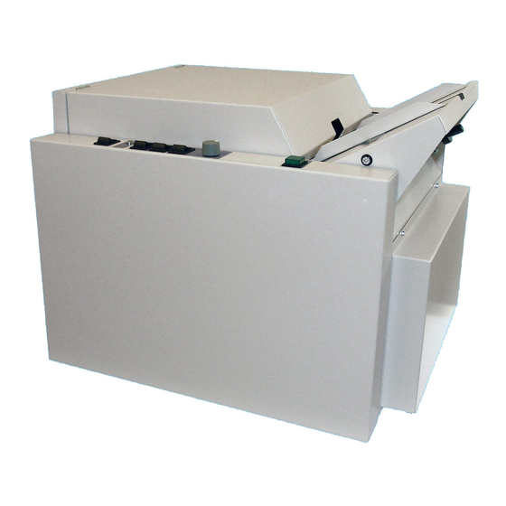
- Page 1 Plockmatic BM 60/61 Bookletmaker Service Manual Provided By http://www.MyBinding.com http://www.MyBindingBlog.com...
- Page 2 Stapler/Folder Model 60/61 Service manual OCTOBER 1994...
- Page 3 i Contents T08011 TJ PAGE INTRODUCTION OCTOBER -94 COVER REMOVE INSTRUCTION (CRI) CRI 1.1 Front and rear cover OCTOBER -94 CRI 1.2 Infeed and outfeed covers OCTOBER -94 REPAIRS/ADJUSTMENTS (REP) REP 2.1 Parallelity Fold knife - Anvil bar OCTOBER -94 REP 2.2 Adjustment of Side guides Model 60 OCTOBER -94...
- Page 4 Model 60/61. PLOCKMATIC CHISEL POINT STAPLES The staples that should be used in the Model 60/61 are PLOCKMATIC chisel point staples, part number 800001. When using PLOCKMATIC staples functional disorders are avoided and the life length of the stapler heads are radically increased.
- Page 5 CRI 1.1 Front and rear cover T08010 TJ FRONT COVER REMOVAL 1. Loosen the two screws (1). 2. Pull out the lower end and lift up to remove. CAUTION: Lift carefully when removing front cover to prevent damaging the wire harness to front panel.
- Page 6 CRI 1.2 Infeed and outfeed cover T08010 TJ UPPER/LOWER INFEED COVER REMOVAL 1. Remove the two screws (1). 2. Pull out the upper end of Lower infeed cover and open cover to horizontal position. 3. Remove the screws (2) and remove the upper infeed cover. INSTALLATION 1.
- Page 7 REP 2.1 Parallelity Fold knife - Anvil bar T08008 TJ PURPOSE The purpose is to align the Anvil bar with the Fold knife to obtain a correct staple position. 1. Switch off the main power switch and disconnect the power cord. 2.
- Page 8 REP 2.2 Adjustment of Side guides Model 60 T08008 TJ PURPOSE Side guides needs to have the correct position in order to transport the set straight to the fold stop. 1. Switch off the main power switch and disconnect the power cord. 2.
- Page 9 REP 2.3 Adjustment of Side guides Model 61 T08009 TJ PURPOSE The Side guides needs to be exactly parallel in order to transport the set straight to the Fold stop. 1. Switch off the main power switch and disconnect the power cord. 2.
- Page 10 REP 2.4 Adjustment of side jogger movement Model 61 T08009 TJ PURPOSE On the Model 61 the side jogging is performed with the rear jogging rail. The jogging stroke is essential to the jogging performance and the transport of stets to the fold area. 1.
- Page 11 REP 2.5 Parallelity Staple stop - Anvils T08009 TJ PURPOSE The purpose is to obtain the correct staple position. 1. Switch off the main power switch and disconnect the power cord. 2. Empty Staple magazines. 3. Insert tool B according to the drawing and crank hand wheel to position upper edge of tool at Anvils.
- Page 12 REP 2.6 Parallelity Fold stop - Fold knife T08009 TJ PURPOSE The purpose is to obtain the correct folding position. 1. Switch off the main power switch and disconnect the power cord. 2. Remove Outfeed cover, CRI 1.2. 3. Move Fold knife to top position by turning the shaft on rear side of fold knife motor manually. 4.
- Page 13 REP 2.7 Positioning staples on fold T08009 TJ PURPOSE The distance between the fold stop and the fold knife should be equal to the distance between the fold knife and the staple outlet. Regardless of where the fold is positioned the staples should always be on the fold.
- Page 14 REP 2.8 Adjustment stapler position to Anvil T08009 TJ PURPOSE By checking the staples on a stapled set you can easely determine if the staple outlet on the stapler head is positioned on top of the slot in the anvil. 1.
- Page 15 REP 2.9 Adjustment stapler pressure T08009 TJ PURPOSE It is possible to staple through 22 sheets of paper without adjusting the stapler pressure. The stapler pressure should increase when thick sets are stapled. To make this possible a piece of spring steel is mounted underneath the stapling bracket. If stapler pressure is incorrect adjusted, staples will be loose when stapling two sheets.
- Page 16 REP 2.10 Home position Stapler motor M1 T08009 TJ PURPOSE Switch SW7 stops the Stapler motor at home position. There are two springs that holds the Stapler yoke in top position when Stapler motor is in home position. 1. Switch off the main power switch and disconnect the power cord. 2.
- Page 17 REP 2.11 Home position Knife motor M2 T08009 TJ PURPOSE Switch SW8 stops the Knife motor at home position. 1. Remove Front and Infeed cover, CRI 1.1 and 1.2. 2. Select folding on front panel. 3. Run one set of paper trough and check that the Fold knife stops below the paper path according to the drawing.
- Page 18 REP 2.12 Adjustment of Eject Idler roller T08009 TJ PURPOSE The upper Idler roller has to be positioned at the correct height in order for the Eject motor feed wheel to feed the set to the Fold stop. 1. Switch off the main power switch and disconnect the power cord. 2.
- Page 19 REP 2.13 Adjustment of Eject motor M4 T08009 TJ PURPOSE There should be a clearance between the Idler roller and the Eject feed wheel when Solenoid SOL1 is activated. If Idler roller and Feed wheel are touching there could be a problem to feed sets with large sizes (A3/11"x17").
- Page 20 REP 2.14 Aligning Eject rollers T08009 TJ PURPOSE This adjustment is more essential on the Model 61, when the set is fed to the Fold stop on a Model the inner Side jogger rail will not guide the set as on a Model 60. 1.
- Page 21 REP 2.15 Removal of lower Fold rollers T08009 TJ REMOVE 1. Switch off the main power switch and disconnect the power cord. 2. Remove Front cover, CRI 1.1. 3. Remove the springs (1), use a screwdriver to compress the springs when removing. 4.
- Page 22 REP 2.16 Fold pressure, top Fold rollers T08009 TJ PURPOSE There are two springs on each side of the top Fold rollers, one is stiff and the other is softer. When running two to five sheets the Fold rollers will only use the soft springs, when running up to twenty sheets all of the springs will be compressed.
- Page 23 REP 2.17 Removal of Infeed Motor M6 assembly, Model 61 T08009 TJ PURPOSE By removing the infeed motor assembly you will have an easy access to the infeed motor and infeed roller. 1. Switch off the main power switch and disconnect the power cord. 2.
- Page 24 REP 2.18 Removal of Stapler head T08009 TJ REMOVAL 1. Switch off the main power switch and disconnect the power cord. 2. Remove the Stapler head by removing the pin 1 trough the hole 2. NOTE. Older machines does not have the hole 2 in the stapler bracket. On these machines the screws 3 has to be removed in order to remove the stapler head.
- Page 25 EDI 3.1 Trimming of Circuit board PCB 60-1 T08009 TJ PURPOSE The trimmers on the circuit board can be adjusted in order to increase or decrease the different functions described below. If exchanging a circuit board position of the trimmers has to checked. SETTING OF TRIMMERS 9 O’clock...
- Page 30 FIP 4.1 Fault isolating procedure Model 61 T08012 TJ Observed fault P ossible cause F ault isolating/repair No machine initialisation. Power supply not connected. Check voltage in power cord. Main fuse F3 defective. Check fuse at power receptacle. Secondary fuses F1 & F2 Check fuses at circuit board defective.
- Page 31 FIP 4.1 Fault isolating procedure Model 61 T08012 TJ Observed fault P ossible cause F ault isolating/repair Stapler motor M1 Fuse F2 defective. Check fuse F2 at circuit inoperative. PCB PL 60. Main circuit board PCB PL60 Check for app. 34 VDC at defective.
- Page 32 FIP 4.1 Fault isolating procedure Model 61 T08012 TJ Observed fault P ossible cause F ault isolating/repair Fold knife motor M2 Home position switch SW8 Check function of home cycles continuously. defective. position switch SW8, see REP 2.11. Main circuit board PL60 Replace PCB PL60.
- Page 33 FIP 4.1 Fault isolating procedure Model 61 T08012 TJ Observed fault P ossible cause F ault isolating/repair False jam indication Main circuit board PL60 Check for app. 24 VDC at from Model 61. defective. connector J1 between pin 10 and common ground. Circuit board PL61 Check for app.
- Page 34 FIP 4.2 Fault isolating procedure Model 60 T08012 TJ Observed fault P ossible cause F ault isolating/repair No machine initialisation. Power supply not connected. Check voltage in power cord. Main fuse F3 defective. Check fuse at power receptacle. Secondary fuses F1 & F2 Check fuses at circuit board defective.
- Page 35 FIP 4.2 Fault isolating procedure Model 60 T08012 TJ Observed fault P ossible cause F ault isolating/repair Stapler motor M1 Home position switch SW7 Check function of home cycles continuously. defective. position switch SW7, see REP 2.10. Main circuit board PCB PL60 Replace PCB PL60.
- Page 36 FIP 4.2 Fault isolating procedure Model 60 T08012 TJ Observed fault P ossible cause F ault isolating/repair Belt stacker motor M5 Main circuit board PCB 60 Check for 24 VDC at inoperative. defective. connector J6 between pin 1 & 2. Belt stacker motor M5 Check for 24 VDC at defective.
- Page 37 MAI 5.1 Preventive Maintenance Preventive Maintenance Bookletmaker Model 60 / 61 Service interval: 80 000 Note: All INSTRUCTIONS are referring to the Stapler folder Model 60 / 61 Service Manual. The REFERENCE column is referring to the Spare parts list of Model 60 / 61 revision date November 1994.
- Page 38 v i t u l f f I . e t I c i t . ) x e t I c i l e t I e l l s i l l e l t e l y t i t e l y t i .
Need help?
Do you have a question about the BM 60 and is the answer not in the manual?
Questions and answers