
Related Manuals for Thrane&Thrane TT-3020C


Summary of Contents for Thrane&Thrane TT-3020C
- Page 1 ® VMS Capsat Transceiver TT-3020C, TT-3022C, TT-3022D and TT-3028CM Configuration Manual...
- Page 4 Thrane & Thrane ® VMS Capsat Transceiver TT-3020C, TT-3022C, TT-3022D and TT-3028CM Configuration Manual Copyright © Thrane & Thrane A/S ALL RIGHTS RESERVED...
- Page 5 Information in this document is subject to change without notice and does not represent a commitment on the part of Thrane & Thrane A/S. © 2000 Thrane & Thrane A/S . All right reserved. Printed in Den- mark. Document Number TT98 -112168-B. Release Date: 9.
-
Page 7: Table Of Contents
2.1.2 First part of Positioning Report ..........2.3 2.1.3 Second Part of Positioning Report........2.5 Initial setup of transceiver ................3-1 TT-3020C SOLAS Transceiver ............3-1 3.1.1 Making a SOLAS Fishery Transceiver ........3-1 3.1.2 Ocean Registration ..............3-2 TT-3028CM Dual Mode Fishery Transceiver ........3-3 3.2.1... - Page 8 Table of Contents 4.1.8 Nice power down support ............4-8 4.1.9 Disable Send LED on position report T X......4-11 4.1.10 Stop button initiates position report........4-11 4.1.11 Disable position report infos..........4-13 4.1.12 Password on da-command ..........4-13 4.1.13 Only 1 packet per position report ........4-14 4.1.14 Mask out speed and course ..........4-14 4.1.15...
- Page 9 Table of Contents 9-Nov-00 Page iii...
- Page 11 Figure 3 API header of DNID file ................2.2 Figure 4 First Part of Position Rep ort ...............2.3 Figure 5 Second Part of Position Report ..............2.5 Figure 6 TT-3020C Maritime Capsat Transceiver ..........3-1 Figure 7 TT-3020C Maritime Capsat Transceiver ..........3-3 Figure 8TT-3022D Fishery Capsat Transceiver.............3-5 Figure 9 TT-3022C Land Mobile Transceiver............3-6...
- Page 12 Table of Figures This page is intentionally left blank Page vi 9-Nov-00...
- Page 13 Table of Tables Table of Tables Table 1 Position report format 2 ................4-4 Table 2 Position report format 3 ................4-5 Table 3 Default Macro Encoded Messages ............4-19 Table 4 Password Protected Commands ............4-25 Table 5 Sleep Mode Command ................4-32 Table 6 Possible zone shapes ................4-34 Table 7 T&T Remote Configuration ................5-1 Table 8 T&T Poll Command List................5-3 Table 9 Connection between entry number and parameters.
- Page 14 Table of Tables This page is intentionally left blank Page viii 9-Nov-00...
-
Page 15: Introduction
Thrane fishery transceivers and land mobile transceiver for use in Vessel /Vehicle Monitoring Systems. The manual provides informa- tion for both the TT-3020C SOLAS GMDSS Transceiver, the TT- 3028CM Dual Mode SOLAS GMDSS Transceiver, the TT-3022D Non-SOLAS Fishery Transceiver and for the TT-3022C Land Mobile Transceiver. -
Page 16: Figure 1 System Overview
T h r a n e & T h r a n e P o w e r L o g i n S e n d Mail T T - 3 0 2 2 C LES312 TT-3022D, TT-3020C, TT-3028CM, TT-3022C LES204 Figure 2 LES, DNID and member number Page 1-2 9-Nov-00... -
Page 17: Short Feature Description
Short feature description Introduction The member number has a similar meaning as the return address on an envelope. The member number is used by the ves - s el/vehicle surveillance centre to identify the transceiver that transmitted the position report. When a position report is received by the Land Earth Station (LES) a DNID file is created from the packets received in the VMS DNID mailbox. - Page 18 Introduction Short feature description • Configurable one or two packets report depending on the need for speed and course information. • 4 different formats for date and time information • Remote configuration from VMS centre of key features in the transceiver.
-
Page 19: Restriction To The Solas Fishery
Some of the features described in this manual are in conflict with the SOLAS GMDSS requirements. Therefore thes e features are not implemented in the TT-3020C SOLAS Fishery Transceiver or in the TT-3028CM Dual Mode SOLAS GMDSS Transceiver. A short list of the missing features are listed in the following. A more comprehensive description of the feature is given in th e rele- vant sections of this manual. - Page 20 Introduction Short feature description This page is intentionally left blank Page 1-6 9-Nov-00...
-
Page 21: Les Interface
DNID Common Format LES Interface LES Interface This manual does not discuss the interface between the Vessel Monitoring Centre and the Inmarsat-C Land Earth Station . However a description of the DNID file format is discussed in section 2.1 as this should give a good hand -on feeling of the actual information that can be passed between the Vessel Monitoring Unit and the Vessel Monitoring Centre. -
Page 22: Api Header Format
LES Interface DNID Common Format 2.1.1 API Header Format 1 byte Indication of header start (EOH) ‘T’ 3 by tes ASCII values for string "T&T" i.e. byte values 54H,26H,54H ‘&’ ‘T’ 1 byte Type of API header (01 for DNID header) 1 byte The length of this header in bytes... -
Page 23: First Part Of Positioning Report
Cat (2 bits) The Category is set to 01B (Maritime) in all Position Reports gen- erated by the TT-3020C SOLAS Fishery, the TT-3028CM Dual Mode SOLAS GMDSS Transceiver, the TT-3022 D Non SOLAS Fis hery transceiver and the TT-3022C Land Mobile Transceiver if confi g- ured for VMS . - Page 24 LES Interface DNID Common Format Hemisphere (1 bit) A North/South flag. Set to 0 for North or 1 for South. Degrees (7 bits) The degrees of Latitude, North or South. 1 ° being 60 minutes. Minutes (6 bits) The integer part of the Minutes of latitude. 1 minute being 1 nautical mile - 1852 meters Fractional part (5 bits) The fractional part of the Minutes of latitude in units of 0.04 of a...
-
Page 25: Second Part Of Positioning Report
DNID Common Format LES Interface The integer part of the Minutes of longitude. Fractional part (5 bits) The fractional part of the Minutes of longitude in units of 0.04 of a Minute. 2.1.2.3 Macro Encoded Message (MEM) (7 bits) A Macro Encoded Message (MEM) is a pre-defined message rep- resented by a unique 7 bit code. - Page 26 LES Interface DNID Common Format The format of the speed and course field are described in the fo l- lowing. 2.1.3.1 Speed (1 byte) Speed is coded as a one byte unsigned binary number with a res olution of 0.2 knots. If no valid data is available at the MES, the field should be set to "FFH".
-
Page 27: Initial Setup Of Transceiver
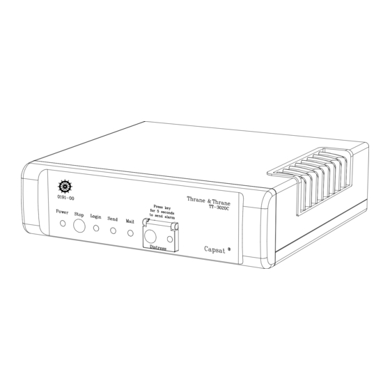
V3.24 or above is approved for both GMDSS and fishery surveillance. Figure 6 TT-3020C Maritime Capsat Transceiver When receiving the transceiver the TT-3020C is default set to SO- LAS Maritime behaviour i.e. no fishery surveillance is enabled. Some configurations are necessary before setting the transceiver on-air to fulfil the VMS requirements. -
Page 28: Ocean Registration
The transceiver will automatically reboot when changing tran s - ceiver type and after power-up identify itself as a SOLAS Fishery transceiver. TT-3020C SOLAS Fishery does not allow external position to set the position of t h e transceiver and therefore NMEA input is dis - abled. -
Page 29: Tt-3028Cm Dual Mode Fishery Transceiver
V3.24 or above is approved fo r both GMDSS and fishery surveillance. Figure 7 TT-3020C Maritime Capsat Transceiver When receiving the transceiver the TT-3028CM is default set to SOLAS Maritime behaviour i.e. no fis hery surveillance is enabled. -
Page 30: Ocean Registration
Initial setup of transceiver TT-3028CM Dual Mode Fishery Transceiver MES into SOLAS Fishery transceiver changes the transceiver into a SOLAS Fishery transceiver. Please notice that once the transceiver has been changed to a SOLAS Fishery it is no longer possible to change it back to a normal SOLAS Maritime transceiver. -
Page 31: Tt-3022D Fishery Transceiver
TT-3022D Fishery Transceiver Initial setup of transceiver TT-3022D Fishery Transceiver The TT-3022D is an Inmarsat-C transceiver for Non-SOLAS appli- cations. All software version can be used for fishery surveillance but this manual describes feature available in V3.27 and above. When receiving the transceiver the TT-3022D is default set without fishery surveillance. -
Page 32: Tt-3022C Landmobile Transceiver
Initial setup of transceiver TT-3022C Landmobile Transceiver TT-3022C Landmobile Transceiver The TT-3022C is a Inmarsat-C transceiver approved for Landmo- bile applications. When the transceiver has installed software ve r- sion V3.27 or above, it is approved for vehicle surveillance(VMS). Figure 9 TT-3022C Land Mobile Transceiver When receiving the transceiver the TT-3022C is default set to no r- mal landmobile behaviour i.e. -
Page 33: Ocean Registration
TT-3022C Landmobile Trans ceiver Initial setup of transceiver 3.4.2 Ocean Registration When the transceiver is configured for vehicle surveillance the transceiver will automatically login to the ocean region with the best signal (if not already logged in). Using the transceiver te rminal command "SET -O"... - Page 34 Initial setup of transceiver TT-3022C Landmobile Transceiver This page is intentionally left blank Page 3-8 9-Nov-00...
-
Page 35: Transceiver Configuration
Configuring the VMS behaviour Transceiver Configuration Transceiver Configuration This chapter provides specific information enabling you to config- ure the VMS functionality on one of the Thrane & Thrane Inmarsat- C transceivers with a minimal effort. The transceivers can be configured to a wide range of different VMS functionality’s. -
Page 36: Quit
Transceiver Configuration Configuring the VMS behaviour Fishery configuration Field Current setting(s) 0 : Quit 1 : Set all values to default 10 : Date and time format : Default 20 : Antenna Blocked/Disconn followed by normal position report : no 21 : Retransmit fail reports : no 22 : Blocked GPS detection... -
Page 37: Set All Values To Default
Configuring the VMS behaviour Transceiver Configuration The Quit command is executed by entering 0 in the fishery com- mand entry. 4.1.2 Set all values to default This entry sets the configuration of the transceiver to default VMS behaviour. The default values are described in each entry d escrip- tion. - Page 38 Transceiver Configuration Configuring the VMS behaviour Additional date of position information is coded as: [Additional date of position]::= [Month][Year[not used] Month Year 4 bits: full month information. Month 1-12 Year not used 6 bits: 00 - 63: i.e. gives year 1997 - 2060 year added to 1997 Figure 11 Position report format 1...
- Page 39 Configuring the VMS behaviour Transceiver Configuration S(1 bit) Spare Year(7 bit) 00 - 99: i.e. gives year 1998 – 2097 Month(4 bit) 1-12: full month information Day(5 bit) 1-31: day of the month (same field as in normal A ttribute) Hour(5 bit) 0-23: hour of the day (same field as in normal Attribute)
-
Page 40: Antenna Blocked/Disconnected Followed By Normal Position Report
Transceiver Configuration Configuring the VMS behaviour 4.1.4 Antenna Blocked/Disconnected followed by normal position report If this entry is set to Yes every antenna blocked and antenna di s - connected position report is followed by a normal position report that includes the current position. Position First report includes position... -
Page 41: Blocked Gps Detection
Configuring the VMS behaviour Transceiver Configuration 4.1.6 Blocked GPS detection If this entry is set to Yes blockage detection on the GPS signal is done parallel to the blockage detection of the Inmarsat NCS TDM signal. If the GPS has no fix for 4½ minutes an antenna blocked position report will transmitted when the signal becomes OK again. -
Page 42: Nice Power Down Support
Transceiver Configuration Configuring the VMS behaviour then • the positioning reporting program using the connection will be changed to the short reporting interval configured in Reporting intervals The change in position is checked every 5 minutes. Position Interval changed because vessel has moved 400m from harbor... - Page 43 Configuring the VMS behaviour Transceiver Configuration If set to Yes the sleep mode functionality (see section 4.5 ) of the transceiver can be used to configured the transceiver for nice power down. Nice power down is used when it is necessary to separate "supply power removed abruptly"...
- Page 44 Transceiver Configuration Configuring the VMS behaviour Mode Report" ~1-5 min after transceiver is switched off and "Leave Sleep Mode Report" when transceiver is switched on again. The " Enter Sleep Mode Report " includes position at the time of transceiver is switched off. The " Leave Sleep Mode Report "...
-
Page 45: Disable Send Led On Position Report Tx
Configuring the VMS behaviour Transceiver Configuration 4.1.9 Disable Send LED on position report TX Please notice that this command is not supported in the TT- 3020C SOLAS Fishery Transceiver nor in the TT-3028CM Dual Mode SOLAS Fishery transceiver. This entry is used to configure that the transceiver does not light up the Send LED when transmitting position reports. -
Page 46: Figure 14 In-Port Button
Transceiver Configuration Configuring the VMS behaviour When pressing the Stop button less than 4 seconds the button has normal functionality i.e. acknowledging messages. 4.1.10.2 Set transceiver In-Port mode If the entry is set to Yes/in-port mode then the stop button has the same functionality as described in section 4.1.10.1 however: •... -
Page 47: Disable Position Report Infos
Configuring the VMS behaviour Transceiver Configuration 4.1.11 Disable position report infos. If this entry is set to Yes the transceiver will not display any INFO messages related to VMS position reporting. It is recommended that this entry is configured to Yes if information regarding VMS should be kept hidden from the operator. -
Page 48: Only 1 Packet Per Position Report
Transceiver Configuration Configuring the VMS behaviour If the Hide remote connections entry is set to No then this entry could be set to Yes because then only VMS DNIDs are hidden from the operator. Additional DNIDs downloaded by other authorities are shown to the operator and therefore a protection of these DNID can be a c- complished by removing the possibility of sending data report to these DNIDs. -
Page 49: Disable Gps First Fix Beep
Configuring the VMS behaviour Transceiver Configuration This entry can also be configured remotely. This feature is only useful where local regulations prohibits the a uthorities from ge tting this information from the vessel/vehicle. The feature is configured by entering 32 in the fishery command entry. -
Page 50: Use Vms Dnid For Special Reports
Transceiver Configuration Configuring the VMS behav iour The feature is configured by entering 34 in the fishery command entry. 4.1.17 Use VMS DNID for special reports If this entry is set to Yes then Only the account on the LES for the (DNID, LES) pair described in 4.1.25 VMS DNID and 4.1.25 VMS LES will receive the special position reports transmitted by the transceiver. -
Page 51: Hide Remote Connections
Configuring the VMS behaviour Transceiver Configuration transceiver. This setting is not recommended due to the fact that remote configured Inmarsat PU interval program can only be set- up for one ocean region at a time. The special reports are all position reports i.e.: •... -
Page 52: Keep Inactive Connections
Transceiver Configuration Configuring the VMS behaviour The feature is configured by entering 36 in the fishery command entry. 4.1.19 Keep inactive connections When a connection has no DNID in the ocean region where the transceiver is logged in, the connection is inactive. Inactive connec- tions are normally removed, but setting this option to yes will pr e- vent the removal. -
Page 53: Number Of Positions In Storage Queue
Table 3 Default Macro Encoded Messages Please notice that Macro Encode Messages 6 + 7 + 8 and 9 are unavailable in the TT-3020C/TT-3028CM SOLAS Fishery Trans - ceivers due to the fact that Sleep Mode not is implemented in the SOLAS Transceivers. -
Page 54: Position Report Packet 2 - Bit Mask
Transceiver Configuration Configuring the VMS behaviour When the Inmarsat-C signal is blocked for approximately 11½ minutes (80 Inmarsat TDM frames) and the GPS signal is still pr e- sent the transceiver will go into a mode where it stores positions in non-volatile memory. -
Page 55: Reporting Intervals
Currently the TT-3606E Mes - sage Terminal does not support this option. A Message Terminal used for the TT-3020C/TT-3028CM SOLAS Fishery Transceiver must be approved by Inmarsat and therefore only very few Message Terminals are suited to fit this transceiver. -
Page 56: Reporting Interval Change Distance
Transceiver Configuration Configuring the VMS behaviour The reporting intervals configuration are used together with the fo l- lowing items: Long to short report interval change (please see sec- tion 4.1.7), Set transceiver In-Port mode (please see section 4.1.10.2) and in Number of positions in storage queue (please see section 4.1.21). -
Page 57: Number Of Active Dnid In Transceiver
Transceiver Configuration The VMS DNID and VMS LES entry can not be configured remotely unless the fishery configuration “ ' A' in provider downloads VMS DNID ” (page 4-15) is set to Yes but it is recommended that fixed VMS DNID, LES pairs are used and that the fishery con figuration entry “'A' in provider downloads VMS DNID”... - Page 58 Transceiver Configuration Password protection it is possible for anyone to change the behaviour of the transceiver. The transceiver allows passwords up to 8 characters. The terminal command "SET -D N" is used to enter a new pas s - word. When password protection is applied some features cannot be accessed more unless the password is known.
-
Page 59: Table 4 Password Protected Commands
FI 35 = No connection Display a local connection PG -D FI 35 = No Login (TT-3022D) always Scan (TT-3022D) NC -S always Login (TT-3020C/TT-3028CM) Never protected Scan (TT-3020C/TT-3028CM) NC -S Never protected Zone Always Table 4 Password Protected Commands 9-Nov-00 Page 4-25... -
Page 60: Automatic Ocean Region Shift
Transceiver Configuration Automatic ocean region shift Automatic ocean region shift Please notice that this command is not supported in the TT- 3020C SOLAS Fishery Transceiver nor in the TT-3028CM Dual Mode SOLAS Fishery transceiver. The transceiver can be configured to perform automatic ocean re- gion shift depending on either position or signal strength. -
Page 61: Reduced Transmission Mode
Transceiver Configuration Reduced transmission mode The transceiver can be configured to run in reduced mode where the number of transmitted position reports are limited - and con- sequently the airtime costs are reduced. By using the reduced transmission mode this can be accomplished without reducing the efficiency of the surveillance. -
Page 62: Figure 15 Reduced Transmission Mode
Transmission Mode Report" Figure 15 Reduced Transmission Mode Please note that the sleep mode functionality in mode 2 of “Re- duced transmission mode” cannot be used in the TT-3020C/TT- 3028CM SOLAS Fishery Transceiver. The following example illustrates the used of reduced mode. -
Page 63: Figure 17 Position, Speed And Course Shown Graphically
Reduced transmission mode Transceiver Configuration A fishery vessel that sails at sea or a vehicle on the road returns its position, speed and course at regular intervals. The positions from a vessel/vehicle shown in Figure 17 indicates that the ves - sel/vehicle has moved as shown in Figure 18. -
Page 64: Sleep Mode
Transceiver Configuration Sleep mode The number of position report is reduced because the ves - sel/vehicle at the time of interval reporting checks whether or not it is still inside the radius of reduced mode as configured in the fis h- ery configuration entry “Reporting interval change distance”... -
Page 65: Setting Up Sleep Mode Operation
Sleep mode Transceiver Configuration Power Switch - namely abruptly removing the power supply from the transceiver. No matter the configuration the ON/OFF button S1 - Main Power Switch - on the rear panel of the transceiver will always have same effect as cutting the main po wer supply i.e. -
Page 66: Table 5 Sleep Mode Command
Transceiver Configuration Sleep mode Option Description Detail Show sleep mode status. Set-up sleep Where: <T1>, mode operation. T1: 0 - 24, Duration in hours the <HH>, transceiver sleeps between wake ups. <MM>, If T1=0, then there are no periodic wake <T2>... -
Page 67: Surveillance Zones
Surveillance zones Transceiver Configuration it has prepared the next wakeup time and this can eas ily take up to 1 minute if the transceiver is not engaged in other traffic. • Transceiver will wake up 1 minute after going to sleep and transmit an "Enter Sleep Mode Report". -
Page 68: Figure 21 Zone Example
Transceiver Configuration Surveillance zones Zone Shape Limits type Circle Min radius 1 km Max radius 65535 km (40000 km) Polygon with 3 positions Max angle between sides = 180° Polygon with 4 positions Max angle between sides = 180° Polygon with 5 positions Max angle between sides = 180°... -
Page 69: Setting Up Surveillance Zones
Surveillance zones Transceiver Configuration If an invalid shape or invalid data is programmed the entire zone is ignored. When zones overlap the zone with the highest priority (lowest number) will determine the reporting interval. 4.6.1 Setting up surveillance zones Purpose: Control surveillance zones. - Page 70 Transceiver Configuration Surveillance zones Octagon -o "zonenumber","radius" Add/Change the zone radius. "radius" = "1" - "65535" -p "zonenumber","positionnumber"," lat deg","lat min","lat dsec","hemNS","lon deg","lon min","lon dsec","hemEW" Add/Change a position in a zone. "positionnumber" = "1" - "8" "lat de g" = "0" - "90" "lat min"...
-
Page 71: Remote Configuration Of The Transceiver Via Poll
VMS Configuration Remote configuration of the transceiver via poll Remote configuration the transceiver via poll VMS Configuration The following poll to sub-address 1 is defined by T&T: Poll command Command Meaning number name 6CH (108) T&T Remote This poll is used to configure the configuration transceiver remotely Table 7 T&T Remote Configuration... - Page 72 Remote configuration of the transceiver via poll VMS Configuration Zero field (1 byte) Value 00H. Command array [Command array] ::= [Packet Descriptor ][AckRef ][Type dependent fields [Checksum ]...[Packet Descriptor ] [AckRef ][Type dependent fields ][Checksum Packet Descriptor The packet descriptor field has the same format as the Inmarsat packet descriptor, short and medium packet descriptor are sup- ported.
-
Page 73: Table 8 T&T Poll Command List
VMS Configuration Remote configuration of the transceiver via poll Medium (2 bit) Value 2 (10 binary) Type (6 bit) This field contains the command type that must be executed in the transceiver. Please refer to 0 Length (8 bit) Number of bytes from the end of the [Length] field that is a part of this command. -
Page 74: Figure 22 Poll Command Checksum Calculation
Remote configuration of the transceiver via poll VMS Configuration Checksum (16 bit) The [AckRef] and [Type dependent fields] are included in chec k- sum calculation. Checksum is calculated in the following way (same way as the checksum for normal Inmarsat packets ).: Figure 22 Poll Command Checksum Calculation Page 5-4 9-Nov-00... -
Page 75: Fishery Configuration (Fi Command) Poll
Fishery Configuration (FI command) Poll Remote configuration of the transceiver via poll Fishery Configuration (FI command) Poll Type dependent fields [Type dependent fields] ::= [Entry No][Parameters] Entry No (1 byte) First parameter of the FI command. This is the entry of FI configura- tion what is normally entered in “Enter field number >”. - Page 76 Remote configuration of the transceiver via poll Fishery Configuration (FI command) Poll Entry Description Parameter( s ) Date and time format Value: 0,1,2 or 3 Size: 1 byte Antenna Blocked/Disconn Value: 0 or 1 Size: 1 byte followed by normal position report Retransmit fail reports Value: 0 or 1...
-
Page 77: Zone Configuration Poll
Zone Configuration Poll Remote configuration of the transceiver via poll Reporting intervals (long, Value: 2 intervals ranged from 1 to short in minutes) 9437. Each interval has the size of 2 bytes and must be specified with LSB followed by MSB. Size: 4 bytes Reporting interval change Value: A distance ranged from 15... -
Page 78: Table 10 Connection Between Zone Type And Zone Data
Remote configuration of the transceiver via poll Zone Configuration Poll Zone Description Zone data type No zone <No zone data> Circle [Pos][Radius] Polygon with 3 [Pos ] [Pos ] [Pos sides Polygon with 4 [Pos ] [Pos ] [Pos ] [Pos sides Polygon with 5 [Pos... -
Page 79: Vms Set-Up Acknowledgement
VMS Set-up Acknowledgement Remote configuration of the transceiver via poll Minutes (6 bit) The integer part of the Minutes of latitude. Fractional part (5 bit) The fractional part of the Minutes of latitude in units of 0.04 of a Minute. Longitude (20) [Longitude] ::= [Hemisphere][ Degrees] [Minutes][ Fractional part] Hemisphere (1 bit) - Page 80 Remote configuration of the transceiver via poll VMS Set-up Acknowledgement [Acknowledgement data report] ::= [P][C][Type][DNID][LES ID] [Member no][Category][Sub-Category][Command][Seqno][Spare][Data] Type (6 bit) Value 04H Category (2 bit) Value 02H Sub-Category (6 bit) Value 00H Command (1 byte) Set to same value as the poll command being acknowledged. For Remote configuration poll this field has the value 6CH.
- Page 81 VMS Set-up Acknowledgement Remote configuration of the transceiver via poll Result code Description 0000H No description of the outcome of the poll is included 0004H Missing poll data A new result code 6C is added Result code Description 006CH Remote configuration acknowledge- ment is found in Extended result field [Extended result field for remote configuration poll] ::= [Result...
-
Page 82: Fishery Set-Up Poll Example
Remote configuration of the transceiver via poll Fishery Set-up Poll Example This is the command number identifying the command in the co n- figuration poll. Up to 27 (Result, Command No) pairs can be in- cluded in the response. Fishery Set-up Poll Example The following example shows poll illustrated in Figure 23 send from the LES using T&T PSTN/PSDN dialup interface. -
Page 83: Figure 23 Example Of Remote Poll Configuration
Fishery Set-up Poll Example Remote configuration of the transceiver via poll Remote configuration poll Remote configuration respons (Inmarsat packet descriptor and checksum not shown) (Inmarsat signalling packet descriptor and checksum not shown) Packet 1 DNID MES ID LES ID LES ID Member no Sub adr (01H) Cat. -
Page 84: Vms Connection For Multiple Ocean Regions
Remote configuration of the transceiver via poll VMS connection for multiple ocean regions 31 : Only 1 packet per position report : Yes 32 : Mask out speed and course : No ↵ > po -z 1 i 12345 n 1 491234567 108 0 0 0 1 [00] [05] [05] [1F] [01] [8D] [4E] [05] [06] [20] [00] [88] [52] The value enclosed in brackets ([]) is the hexadecimal value of the byte send to the LES interface. -
Page 85: Figure 24 Open Connection Poll
VMS connection for multiple ocean regions Remote configuration of the transceiver via poll Spare (8 bit) Number of LES, DNID pairs to be linked to this connection (8 bit) LES id. #1 (8 bit) DNID #1 (16 bit) Member #1 (8 bit) Figure 24 Open Connection Poll The LES id is given in Inmarsat-C compressed format (The 2 MSB... -
Page 86: Table 11 Positive Open Connection Acknowledgement
Remote configuration of the transceiver via poll VMS connection for multiple ocean regions connection is modified to contain all (LES id, DNID) pairs included in the poll. 1 0 0 0 0 0 0 0 Command ( 8 bit) Sequence Number (8 bit) Spare (16 bit) Result code = 1 (16 bit) -
Page 87: Sleep Mode Set-Up Poll
Sleep mode Set-up Poll Remote configuration of the transceiver via poll Sleep mode Set-up Poll The command type is 6AH. The poll must be addressed to sub - address 1. The purpose of this poll is to allow remote setting up of sleep mode. -
Page 88: Reduced Transmission Mode Set-Up Poll
Remote configuration of the transceiver via poll Reduced transmission mode set-up poll 30h (T2, Fix time wake up duration = 48 minutes) The acknowledge report will be: 1 0 0 0 0 0 0 0 Command ( 8 bit) Sequence Number (8 bit) Spare (16 bit) Result code (16 bit) -
Page 89: Figure 28 Reduced Mode Acknowledge Report
Reduced transmission mode set-up poll Remote configuration of the transceiver via poll Example of Reduced transmission set-up poll: poll 1 i 12345 n 1 491234567 107 67 <P8> <P9> 1+ followed by one of three bytes: 32h. The acknowledgement report will be: 1 0 0 0 0 0 0 0 Command ( 8 bit) Sequence Number (8 bit) - Page 90 Remote configuration of the transceiver via poll Reduced transmission mode set-up poll This page is intentional left blank Page 5-20 9-Nov-00...
-
Page 91: Development Tips
Reduced transmission mode set-up poll Development tips Development tips This appendix includes some development tips in some cases not specific for a special type of fishery transceiver in other cases very specific for either the TT -3020C, the TT-3028CM or the TT-3022D Fishery transceiver. - Page 92 Development tips Reduced transmission mode s e t-up poll is not allowed to install any of the Fishery Transceivers without a Message terminal. • In TT-3022D setting up the routing to printer only and having terminal command “SE -Z PRINTER=OFF” will result in mes - sages being receive but send directly to the garbage can.
-
Page 93: Index
Index Index Antenna blockage ...................... 1-3 Antenna blocked......................4-6 API headers......................... 2.1 Automatic ocean region shift .................4-26 Checksum ........................5-4 Data packets ....................... 1-3 Date format......................1-4, 4-3 Default.......................... 4-3 DNID ..........................1-1 active ....................4-23 format....................2.1 DNID file........................1-3 EGC reception....................4-20, 6-2 FI command........................ - Page 94 Index Inactive connections....................4-18 Info messages ......................4-13 Land Earth Stations ....................1-1 LES ..........................1-1 Interface....................2.1 Macro codes ....................... 1-4 Main power switch ....................4-31 Manual position report ..................1-4, 4-11 MEM codes........................4-18 Member numbers ...................... 1-1 Mini-M phone ......................3-3 nc ..........................4-1 Channel....................
- Page 95 Send LED ........................4-11 Sleep mode.......................1-4, 4-30 Configuring ..................4-31 SOLAS.......................... 1-5 Special reports ......................4-16 Stop button ........................4-11 Storing of positions ..................1-4, 4-19 Surveillance zones....................4-33 Time format......................1-4, 4-3 Tips ..........................6-1 TT-3022C........................3-6 TT-3020C........................3-1 TT-3022D........................3-5 TT-3028CM........................3-3 9-Nov-00 Page 7-3...
- Page 96 Index Vessel surveillance centre..................1-1 DNID ..............4-15, 4-16, 4-22, 4-23 LES.....................4-22 VMS Data Network Id....................1-1 X.25..........................1-3 Zones .........................4-33 Page 7-4 9-Nov-00...
Need help?
Do you have a question about the TT-3020C and is the answer not in the manual?
Questions and answers