Table of Contents
Advertisement
Auf diesem Inmarsat C Terminal
läuft die Capsat Simulationssoftware
für die LRC (Long Range Certificat) Prüfung
Anmerkungen im Dokument in Teletype Schrift durch
http://funk-an-bord.de
http://funk-an-bord.de
Capsat Transceiver
Installation Manual
I
© Copyright Thrane & Thrane A/S. May 1995
Tobaksvejen 23, DK-2860 Soeborg. Denmark
-- Page 1 of 42 --
TT-3020B
Maritime
a
t ra s
Inmarsat-C Network
t lla
tt-3020b_instalman_S2.pdf
Materialien zur LRC Prüfung
T
a
i e
for the
a
Version 2.20
Advertisement
Table of Contents

Subscribe to Our Youtube Channel
Related Manuals for Thrane&Thrane TT-3020B


Summary of Contents for Thrane&Thrane TT-3020B
- Page 1 Auf diesem Inmarsat C Terminal läuft die Capsat Simulationssoftware für die LRC (Long Range Certificat) Prüfung Anmerkungen im Dokument in Teletype Schrift durch http://funk-an-bord.de TT-3020B Maritime Capsat Transceiver t ra s for the Inmarsat-C Network Installation Manual t lla Version 2.20 tt-3020b_instalman_S2.pdf...
-
Page 2: Table Of Contents
2.4.4 Antenna cable 12 2.4.5 Mounting considerations 13 2.4.5.1 TT-3001B-opt. 001 Maritime Antenna 13 2.4.6 Safety Distance for Antenna Units 15 2.5 TT-3020B Capsat Transceiver 16 2.5.1 Mounting bracket 16 2.5.2 Communication port 16 2.5.2.1 Baudrate and protocol settings 16 2.5.2.2 X4 Connector interface 17... - Page 3 T Thrane & Thrane T T T-3020B C p a Capsat Transceiver Installation Manual 2.6 TT-3606A Message Terminal (optional) 26 Entfernt, da PC 2.6.1 Communication port 26 2.6.2 Printer port 26 2.6.3 VDU Interface 27 2.6.3.1 TT-3602D SVGA Monitor 27 2.6.3.2 TT-3680M DC to DC Converter (70Watt) 28 2.6.4 TT-3601A keyboard 28 2.7 TT-3680A/B Power Supply (optional) 29...
-
Page 4: Introduction
Introduction This manual provides instructions for installing, configuring and testing of a TT-3000 Integrated Capsat System that includes a model TT-3020B Capsat Transceiver. The various Capsat Systems available from Thrane & Thrane are decribed in the manual Integrated Capsat Systems. Please consult this manual if your uncertain what kind of system you will be installing. -
Page 5: Equipment Installation
Contents of the shipment should be as listed in the packing list below. If the contents are incomplete, if there is mechanical damage or defect, or if the TT-3020B Capsat Transceiver does not work properly, notify your dealer. -
Page 6: Packing List
Ma u 2.1.2 Packing list Your Transceiver unit comes in a box with the following parts: Part number t Item Part Name 403022-001 TT-3020B Capsat Transceiver 52-200145-048 HCF 1876 screw, pozi, Fitting the angle or distance mushroom, 4x8mm mountings 33-200192-120... -
Page 7: Storage
Table 1: Packing list. 2.1.3 Storage The TT-3020B may be stored or shipped in temperatures within the limits -40° C to +80° C. It is advisable to protect the TT-3020B from extreme temperature variation which can cause excessive condensation. It is recommended that the TT-3020B is unpacked immediately on delivery. -
Page 8: Technical Specifications
& h T T T-3020B C p a Capsat Transceiver Installation Manual Ma u 2.2 Technical specifications Model TT-3020B General Specifications Meets or exceeds all INMARSAT specifications for the Inmarsat-C Network and GMDSS requirements. Transmit Frequency 1626.5 to 1646.5 MHz. - Page 9 T Thrane & Thrane T T T-3020B C p a Capsat Transceiver Installation Manual Maritime Antenna Inmarsat-C/GPS omnidirectional TT-3001B Opt. 001 antenna, RHC polarized. G/T: -23 dB/K EIRP: 14 dBW ± 2dB at 5° elevation. Temperature: -35°C to55°C operating, -40°C to 80°C storage. Dimensions (H x G): 237 mm x 150 mm conical ex.
-
Page 10: Power Requirements
Table 3: Capsat System component power requirements. 2.3.1 AC mains operation As the TT-3020B Capsat Transceiver is designed to work on floating DC ranging from 10.5 - 32 Volt, an AC/DC converter is needed in case the Transceiver is subject to work in AC environments. -
Page 11: Power Connector
DC-supply the Transceiver will switch on. This makes it possible for other equipment to perform remote power control of the TT-3020B. The remote power control can be triggered by an external relay or solid state switch. -
Page 12: Fuses
Read the safety summary at the front of this manual before installing or operating the TT-3020B Transceiver. As a guide-line, please note the fuse location of the following equipment: Equipment... - Page 13 T Thrane & Thrane T T T-3020B C p a Capsat Transceiver Installation Manual Each unit shall have its own individual low-inductance earth connection. The use of a common busbar for grounding is not recommended as this can lead to unwanted common-mode coupling effects.
-
Page 14: Tt-3001 Antennas
Thrane & Thrane ra e & h T T T-3020B C p a Capsat Transceiver Installation Manual Ma u 2.4 TT-3001 Antennas Figure 1: Maritime antenna. 2.4.1 Antenna types Your Integrated Capsat System has been delivered with a TT-3001B Option 001 Maritime Antenna. -
Page 15: Mounting Bracket
11N-50-7-35 81 - 100 SA12272, 15.0 mm 11N-50-12-35C Table 6: TT-3020B Capsat Transceiver Antenna Cable types All antenna cables types are double shielded. The antenna cable may run together with radar or navigator cables. Separate cable ditch is not required. -
Page 16: Mounting Considerations
Thrane & Thrane ra e & h T T T-3020B C p a Capsat Transceiver Installation Manual Ma u If you install your system in a permanent location, we recommend that you, after the installation of the antenna, wrap the connector with the enclosed self-bonding tape, disabling water from penetrating the connection. - Page 17 T Thrane & Thrane T T T-3020B C p a Capsat Transceiver Installation Manual If an obstruction such as a pole or a funnel is unavoidable, the following guidelines apply: The distance to the obstruction should large enough, so that the obstruction only covers 3 degrees.
-
Page 18: Safety Distance For Antenna Units
Thrane & Thrane ra e & h T T T-3020B C p a Capsat Transceiver Installation Manual Ma u 2.4.6 Safety Distance for Antenna Units The safety levels for the Thrane & Thrane INMARSAT-C Antenna Units are based on the ANSI standard C95.1-1982 "American National Standard Safety Levels With Respect to Human Exposure to Radio Frequency Electromagnetic Fields, 300 kHz to 100 GHz"... -
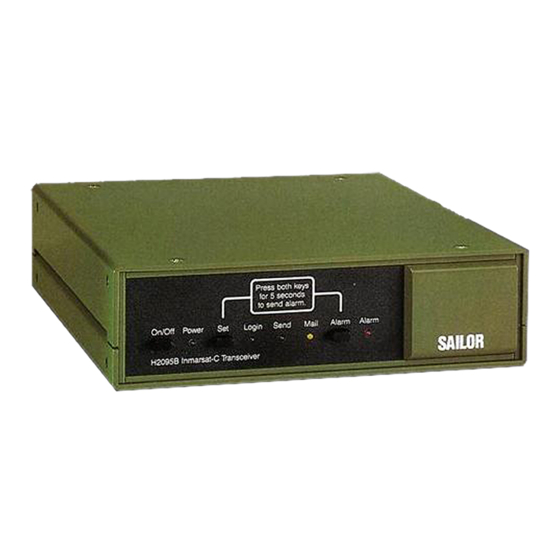
Page 19: Tt-3020B Capsat Transceiver
TT-3606A Message Terminal or the TT-3210A Radiotelex Modem, stacked mounting may be achieved using mounting bracket 41-100742. It is strongly recommended not to stack mount the TT-3020B Capsat Transceiver with the TT-3680A Power Supply because of the heat generation from this unit. -
Page 20: X4 Connector Interface
Please refer to chapter section 3.3 to alter the baudrate and the protocol settings by means of Automatic Baud Rate Recognition. Alternatively these settings may be customer defined. 2.5.2.2 X4 Connector interface The TT-3020B uses the the following signals (marked with a ü in the Used column): Name Signal description 9-Pin... -
Page 21: Tt-3606A Message Terminal
TT-3606A solution. As the TT-3020B rely on the CTS and DTR hardware handshake signals it is very important that the PC you use is IBM hardware compatible with respect to the serial communications interface. -
Page 22: Flow Control
TT-3020B and the peripheral to control data flow by means XON XOFF. ENQ/ACK cannot be used. 2.5.3 T-Bus Connector The T-Bus port X X 5 on the back panel of the TT-3020B Transceiver can be used for either Thrane & Thrane T-Bus communication ²... -
Page 23: Changing Port X5 To Input Nmea 0183 Data
2.5.3.1 Changing port X5 to input NMEA 0183 data If the TT-3020B will be used with a navigator using the NMEA standard, you must follow the below instructions to ensure proper operation: Turn off the TT-3020B . -
Page 24: Switch Settings
Button Button Button Figure 7: TT-3020B CPU Board, No. TT 37-102819, showing the DIP Switch array. Most of the DIP switches inside the TT-3020B Capsat Transceiver are reserved for future use. Page 1 30MAY95 http://funk-an-bord.de -- Page 24 of 42 --... -
Page 25: Jumper Configurations
Capsat Transceiver Installation Manual 2.5.5 Jumper configurations Much of the flexibility of your TT-3020B Capsat Transceiver is due to the extensive use of operator programmable configuration parameters, enabling the user to adjust the TT-3020B to his specific application needs. Most of the configuration parameters are contained in a single integrated circuit, a non- volatile EEPROM. -
Page 26: Nmea 0183 Navigational Interface
Thrane & Thrane ra e & h T T T-3020B C p a Capsat Transceiver Installation Manual Ma u 2.5.7 NMEA 0183 Navigational Interface The following Navigators will provide suitable NMEA 0183 strings to the Capsat Transceiver. AP Navigator Professional APN5 GPS AP Navigator MK6 Raytheon Raystar 920 Furuno GP500 GPS... -
Page 27: Nmea 0183 Transmission
T Thrane & Thrane T T T-3020B C p a Capsat Transceiver Installation Manual 2.5.7.2 NMEA 0183 Transmission When you have a built-in GPS it is possible configure the Transceiver to send out NMEA 0183 navigational data so that devices connected to the Transceiver via the T-Bus connector will benefit from the GPS information. - Page 28 Thrane & Thrane ra e & h T T T-3020B C p a Capsat Transceiver Installation Manual Ma u $GPVTG,139.,T,139.,M,02.0,N,00.0,K $GPGLL,5544.45,N,01228.68,E,, $GPGGA,,5544.45,N,01228.68,E,0,00,1,0,M,,M,, An empty GLL string is sent out when there is no built-in GPS or before the GPS module has been started by the Transceiver.
-
Page 29: Tt-3042B Remote Alarm
The TT-3042B can all the same be used to print out SafetyNet EGC messages, via the built-in thermal printer and indicate reception of EGC messages in general. The TT-3020B Transceiver can accomodate up to 8 Remote Alarms at the same time, but each alarm must have it's own unique T-Bus address in the range 0-7. - Page 30 Thrane & Thrane ra e & h T T T-3020B C p a Capsat Transceiver Installation Manual Ma u The GPS module is installed from the factory and you need not perform any installtion to use it. If you have ordered your Capsat Transceiver without a built-in GPS and you later need to install a GPS module, then you should contact your dealer to obtain the Technical Reference Manual for instuctions on how to accomplish this.
-
Page 31: General Interconnect Information
You can find the other Integrated Capsat System available from Thrane & Thrane in the Integrated Capsat Systems manual. An Integrated Capsat System is delivered with all necessary interconnecting cables. TT-3000C Capsat System Cabling TT-3001B Opt 001 Antenna TT-3020B 61-100921, 0 25m Transceiver 403020-941, 5m 37-102282, 0 25m 37-101436, 0 2m 88-360400-002, 2m... -
Page 32: System Generation
System Generation 3.1 Introduction The System Generation is a special mode that the TT-3020B Capsat Transceiver can enter when powered ON. This mode allows you to change the general operation of the equipment before you start using it for communications. -
Page 33: Terminal Preparation
T T T-3020B C p a Capsat Transceiver Installation Manual 3.2 Terminal preparation Alteration of the TT-3020B Capsat Transceiver parameters may be accomplished by means of: TT-3606A Message Terminal. ² IBM compatible PC running DOS version 2.00 or later, with a communication ²... -
Page 34: Entering The System Generation
10 seconds or at least until you can hear the connected printer being initialized. Now hit the ENTER key and watch the TT-3020B System Generation menu appear on your screen. If this does not happen, repeat steps 1 and 2. -
Page 35: Entering Your Mobile Type And Number
T Thrane & Thrane T T T-3020B C p a Capsat Transceiver Installation Manual 3.4.1 Entering your mobile type and number For ease of operation and general information when you operate your Capsat system, you should consider to enter the mobile number. Just type in the Inmarsat-C 9 digit number that you have received from your PTT authorities. - Page 36 Thrane & Thrane ra e & h T T T-3020B C p a Capsat Transceiver Installation Manual Ma u Mobile number : (unknown) Mobile type : Illegal Select Mobile Type: 0 Illegal 1 Landmobile 2 Maritime Enter number > 2 Please use the Set function on the Capsat Transceiver Note that this can only be done once, as you cannot set the Mobile Number back to the unknown state.
-
Page 37: Leaving The System Generation
The following procedure will bring the Transceiver back to it's normal mode of operation. Select menu entry 0 (zero) Quit, to leave the System Generation. The TT-3020B will ask you to use the S t Set function and hit the ENTER key. -
Page 38: Commissioning Of The Equipment
The commissioning procedure is just a the very first Link Test (or Performance Verification Test in Inmarsat terminology) that the Transceiver performs. The Link Test automatically verifies that the TT-3020B Capsat Transceiver is capable of both receiving and transmitting information according to Inmarsat-C specifications. No other tests are required. -
Page 39: The First Login (Commissioning)
Distress Test. ² The TT-3020B will ask you to perform a manual Distress Test but if you ignore the request the Transceiver will automatically send the Distress Test after 2 minutes. In the end of the test the Transceiver will receive the link test results. -
Page 40: Details Of A Link Test
After a while you will see a message on your screen and on your printer saying: Link Test started and when the MAIL indicator on the TT-3020B frontpanel starts flashing, the receive test has commenced. A test message is then received from the LES by the Transceiver. -
Page 41: Commissioned Status
Though your TT-3020B Transceiver is not commissioned, it is fully capable of receiving messages. You are not denied permission to transmit messages by means of the TT-3020B Capsat Transceiver when your equipment is uncommissioned, but the LES will not forward your messages to their destinations, and a non-delivery notification is returned to you. - Page 42 Thrane & Thrane ra e & h T T T-3020B C p a Capsat Transceiver Installation Manual Ma u —N— N— Index navigator, 20 NMEA 0183 communication, 19 — — O— omnidirectional antenna unit, 12 —P— — — —A— power connector, 8 power requirements, 7 AC mains operation, 7 printer port, 31...
Need help?
Do you have a question about the TT-3020B and is the answer not in the manual?
Questions and answers