Table of Contents
Advertisement
Advertisement
Table of Contents

Related Manuals for Thrane&Thrane SAILOR 6249


Summary of Contents for Thrane&Thrane SAILOR 6249
- Page 1 INSTALLATION MANUAL SAILOR 6249 VHF Survival Craft...
- Page 3 SAILOR 6249 VHF Survival Craft Installation manual Document number: 98-133942-A Release date: October 28, 2011...
- Page 4 Disclaimer Any responsibility or liability for loss or damage in connection with the use of this product and the accompanying documentation is disclaimed by Thrane & Thrane. The information in this manual is provided for information purposes only, is subject to change without notice and may contain errors or inaccuracies.
- Page 5 Thrane & Thrane assumes no liability for the customer's failure to comply with these requirements. Ground the equipment To minimise shock hazard, the SAILOR 6249 VHF Survival Craft unit must be connected to an electrical ground and the cable instructions must be followed. RF exposure hazards and instructions Your Thrane &...
-
Page 6: Record Of Revisions
SAILOR 6249 VHF Survival Craft is designed for installation by a skilled service person. Training information The SAILOR 6249 VHF Survival Craft is designed for occupational use only and is also classified as such. It must be operated by licensed personnel only. It must only be used in the course of employment by individuals aware of both the hazards as well as the way to minimize those hazards The radio is thus NOT intended for use in an uncontrolled environment by general public. - Page 7 Warning Your Thrane & Thrane radio set generates electromagnetic RF (radio frequency) energy when it is transmitting. To ensure that you and those around you are not exposed to excessive amounts of that energy (beyond FCC allowable limits for occupational use) and thus to avoid health hazards from excessive exposure to RF energy, FCC OET bulletin 65 establishes an Maximum Permissible Exposure (MPE) radius of 200 cm for the maximum power of your radio (25W selected) with an half wave omni-directional antenna having a maximum gain of 3 dB (5.2dBi).
-
Page 8: Related Documents
• Service & maintenance contains support information including lists of accessories and a troubleshooting guide. • Appendices with Technical specifications and System configurations. Related documents Title and description Document number SAILOR 6249 VHF Survival Craft, Installation guide 98-133943 SAILOR 6249 VHF Survival Craft User manual 98-133865 Emergency call sheet 98-133795... -
Page 9: Table Of Contents
Troubleshooting guide ..............4-2 Warranty and returning units for repair ..........4-4 Appendix A Technical specifications Transceiver unit SAILOR 6249 VHF Survival Craft ......A-1 SAILOR 6090 Power Converter 24—12 V ........... A-3 Appendix B System configurations System configuration examples ............B-1 Cable requirements .................B-24... - Page 10 Table of contents viii 98-133942-A...
- Page 11 Figure 2-3: Mounting with the mounting bracket..............2-5 Figure 2-4: Drilling plan for the mounting bracket..............2-5 Figure 2-5: SAILOR 6249 VHF Survival Craft Dimension for flush mount ........2-6 Figure 2-6: Cutout for flush mount..................2-6 Figure 2-7: Flush mount ......................2-7 Figure 2-8: SAILOR 6090 Power Converter, dimensions ............2-8...
- Page 12 List of figures Figure B-17: System configuration: CAN bus, 3 SAILOR 6204 CSMs, in bridge wings ....B-19 Figure B-18: System configuration: CAN bus, 4 SAILOR 6204 CSMs, in bridge wings ....B-20 Figure B-19: System configuration: CAN bus, 3 SAILOR 6204 CSMs ........B-21 Figure B-20: System configuration: CAN bus, 4 SAILOR 6204 CSMs ........B-22 Figure B-21:...
- Page 13 List of tables Table Preface-1:Related documents ....................-vi Table 1-1: Accessories available.................... 1-4 Table 2-1: Compass safe distance..................2-3 Table 2-2: Pin allocation, connector at the front panel ............2-9 Table 2-3: Pin allocation, ACC connector................2-11 Table 2-4: Pin allocation, AUX connector ................2-12 Table 2-5: Pin allocation, CTRL connector ................
- Page 14 List of tables 98-133942-A...
-
Page 15: Chapter 1 Introduction
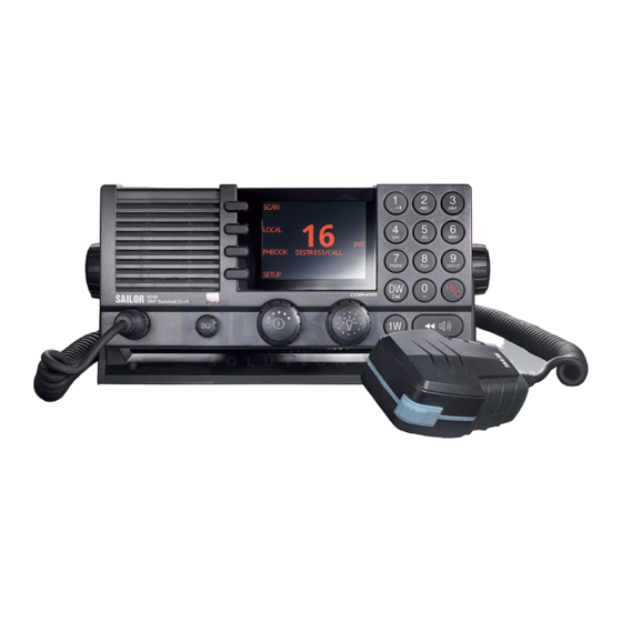
Chapter 1 Introduction VHF radio SAILOR 6249 VHF Survival Craft is designed for use in survival crafts. It is approved to MED and waterproof to the IPx8 and IPx6 standard. As part of the required safety equipment, use the SAILOR 6249 VHF Survival Craft in an emergency situation. - Page 16 VHF radio 1.1.1 Controls on the front plate 1. Loudspeaker. 2. Four soft keys with function title in the display. 3. Large display. 4. Keys 0 to 9 to enter numbers or text. 5. DW button to toggle the watch function. 6.
- Page 17 VHF radio 1.1.2 SAILOR 6249 VHF Survival Craft display The picture shows the display after start-up. The display holds various fields of information, depending on the currently selected function. SCAN PHBOOK 1. Functions you can select with the soft keys.
-
Page 18: Accessories Available
5m connection cable for bulkhead mount: Use cables this cable in installations where the SAILOR 6202 Hand Microphone is not connected directly to the SAILOR 6249 VHF Survival Craft, but located in a different position (part number: 406204-940). SAILOR 6270... -
Page 19: Figure 1-1: System Configuration, Example
Accessories available 1.2.1 System configuration — example The SAILOR 6249 VHF Survival Craft can be customized to suit your installation. The following illustration is one example of a system. For further configuration examples see Appendix B, System configurations. RX/TX Aerial... - Page 20 Accessories available Chapter 1: Introduction 98-133942-A...
-
Page 21: Chapter 2 Installation
• Connectors • VHF antenna installation • Accessories Unpacking and initial inspection The following items are included in the delivery of a SAILOR 6249 VHF Survival Craft: • SAILOR 6249 VHF Survival Craft • SAILOR 6202 Hand microphone • User manual •... -
Page 22: Installing The Vhf Radio
Provide space enough to access the front panel connectors and for installing a cradle for the speaking device. Provide at least 120 mm space at the back of the SAILOR 6249 VHF Survival Craft radio to allow free air circulation and for cable access. -
Page 23: Figure 2-1: Desktop Mounting
SAILOR 6208 Control Unit Connection Box 0.45 m Table 2-1: Compass safe distance 2.2.1 SAILOR 6249 VHF Survival Craft with U mounting bracket The mounting bracket and two knobs are included in the delivery. Desktop mounting Figure 2-1: Desktop mounting... -
Page 24: Figure 2-2: Overhead Mounting
Installing the VHF radio Overhead mounting Figure 2-2: Overhead mounting Mounting with U mounting bracket To mount the VHF radio as tabletop, do as follows: 1. Find a suitable location for the VHF radio. Check that the space is wide/deep enough to accommodate the VHF radio. -
Page 25: Figure 2-3: Mounting With The Mounting Bracket
Installing the VHF radio 4. The display of the VHF radio should be at an angle of approximately 90° to your line of sight when operating it. Figure 2-3: Mounting with the mounting bracket 4 x M4 or hole for self-tapping ø3.9 23.5mm 200mm... -
Page 26: Figure 2-5: Sailor 6249 Vhf Survival Craft Dimension For Flush Mount
You can mount the VHF radio to a flat surface, e.g. an instrument panel. The flush mount installation kit is included in the delivery. Figure 2-5: SAILOR 6249 VHF Survival Craft Dimension for flush mount R2.5mm x 4 Flush mount template... -
Page 27: Figure 2-7: Flush Mount
Installing the VHF radio 5. Ensure that the flush mount gasket is placed correctly on the VHF radio. 6. Before mounting the VHF radio be aware that the surface is plane and rigid. If the surface is not plane and/or rigid (stiff) remove the gasket and seal with silicone sealant between the VHF radio and the surface. -
Page 28: Figure 2-8: Sailor 6090 Power Converter, Dimensions
Installing the VHF radio 2.2.3 SAILOR 6090 Power Converter Figure 2-8: SAILOR 6090 Power Converter, dimensions Remove jumper for remote on/off from VHF Ground 24V DC 12V DC 99-132778 Figure 2-9: Connecting the SAILOR 6090 Power Converter Chapter 2: Installation 98-133942-A... -
Page 29: Connectors
Connectors Connectors 2.3.1 Connector at the front panel for handmicrophone Use the connector at the front of the SAILOR 6249 VHF Survival Craft to connect a SAILOR 6202 Handmicrophone. Connector type: Circular connector, 10pin, male. Panel lock, 10 pin male Connection cable with plug, part number 406209-941. -
Page 30: Figure 2-10: Connections At The Rear Panel
Connectors 2.3.2 Connectors at the rear panel Figure 2-10: Connections at the rear panel 1. ACC connector for accessories 2. AUX connector for VDR, external speaker 3. Power connector PWR FUSE with fuse 10 A mini ATO 4. Ground stud for grounding 5. -
Page 31: Table 2-3: Pin Allocation, Acc Connector
Connectors 2.3.3 ACC connector Use the connector marked ACC to connect a SAILOR 6201 Handset. You may also connect a waterproof SAILOR 6203 Handset or SAILOR 6202 Handmicrophone. Connector type: Circular connector, 10pin, male. Panel lock, 10 pin male Connection cable with plug, part number 406209-941. Pin assignment: Connector front view on the VHF radio. -
Page 32: Table 2-4: Pin Allocation, Aux Connector
Connectors 2.3.4 AUX connector This connector is used to connect VDR external speaker. Connector type: Circular connector, 12pin. Connection cable with plug, part number 406208-941. Pin assignment: Connector front view on the VHF radio: Description Wire color Shield (GND) Brown Lo Power Forced control Blue —... -
Page 33: Table 2-5: Pin Allocation, Ctrl Connector
Connectors 2.3.5 CTRL connector This connector is used to connect a SAILOR 6204 Control Speaker Microphone or SAILOR 6208 Connection Box. Connector type: Circular connector, 12pin. Connection cable with plug, part number 406208-941. Pin assignment: Connector front view on the VHF radio: Description Wire color GND for cable screen... -
Page 34: Table 2-6: Pin Allocation, Lan Connector
To help extract the fuse you can order a fuse puller in the ESHOP at http://extranet.thrane.com/. Pin-out The figure and table below show the connector outline, pin assignments and wire color in the power cable delivered with the SAILOR 6249 VHF Survival Craft. Pin function Wire color DC+ (10.8 - 15,6 V DC) - Page 35 Important The ground stud is located on the rear panel and is used to connect a ground wire for grounding the SAILOR 6249 VHF Survival Craft. To connect the SAILOR 6249 VHF Survival Craft to ship ground, do as follows: 1.
-
Page 36: Vhf Antenna Installation
VHF antenna installation VHF antenna installation The SAILOR 6249 VHF Survival Craft must be installed with one antenna for VHF RX/TX communication. You can install all commonly available 50 Ohm antennas covering the appropriate frequency range and providing a VSWR less than 1.5 over this range. -
Page 37: Accessories
Accessories Accessories 2.5.1 Part numbers for accessories The following accessories are available for the SAILOR 6249 VHF Survival Craft: Part number Accessories available 406202A SAILOR 6202 Hand Microphone 406207A SAILOR 6207 Connection Box with Cable 406209-941 406208A SAILOR 6208 Connection Box with Cable 406208-941... -
Page 38: Figure 2-11: Sailor 6207 Connection Box For Parallel Handsets, Mounting
Accessories 2.5.2 Connection box SAILOR 6207 The SAILOR 6207 Connection Box is used to connect further SAILOR 6201 Handsets. For wiring and cabling details see System configuration examples on page B-1. Figure 2-11: SAILOR 6207 Connection Box for parallel handsets, mounting >... -
Page 39: Figure 2-13: Sailor 6208 Control Unit Connection Box, Mounting
Accessories 2.5.3 Connection box SAILOR 6208 The SAILOR 6208 Connection Box is used to connect SAILOR 6204 Control Speaker microphones and other auxiliary equipment. For wiring and cabling details see System configuration examples on page B-1. Figure 2-13: SAILOR 6208 Control Unit Connection Box, mounting CAN bus termination Jumper for CAN bus termination. -
Page 40: Figure 2-15: Sailor 6208 Control Unit Connection Box, Diagram
Accessories Terminate the last SAILOR 6208 on the CAN bus (furthest away from the transceiver). Figure 2-15: SAILOR 6208 Control Unit Connection Box, diagram 2-20 Chapter 2: Installation 98-133942-A... -
Page 41: Chapter 3 First-Time Power Up
= softer, until muted). When muted, is shown in the display. • To adjust the volume of the handset earpiece see the SAILOR 6249 VHF Survival Craft User manual. 3.1.2 Working channel and changing settings Use the selector knob to browse and select: •... - Page 42 General use and navigation Chapter 3: First-time power up 98-133942-A...
-
Page 43: Chapter 4 Service & Maintenance
4.2.1 Preventive maintenance Maintenance of the SAILOR 6249 VHF Survival Craft can be reduced to a maintenance check at each visit of the service staff. Inspect the radio for mechanical damages, salt deposits, corrosion and any foreign material. Due to its robust construction and ruggedness the radio has a long lifetime. -
Page 44: Troubleshooting Guide
Troubleshooting guide Troubleshooting guide Action Symptom Remedy The radio The display Check if power is present. will not is empty. Check fuse which is placed in the power turn on connector. Check performance of power supply if connected to one. The loud- Check the antenna installation. -
Page 45: Figure 4-1: Fuse In The Power Connector
Troubleshooting guide 4.3.1 Replacing the fuse in the power connector One fuse is installed in the power connector. If the fuse is blown, do as follows: 1. Track down why the fuse was blown and solve the problem. 2. Take out the old fuse. 3. -
Page 46: Warranty And Returning Units For Repair
Should you need to send the product for repair, please read the below information before packing the product. The shipping carton has been carefully designed to protect the SAILOR 6249 VHF Survival Craft and its accessories during shipment. This carton and its associated packing material should be used when repacking for shipment. -
Page 47: Appendix A Technical Specifications
Appendix A Technical specifications Transceiver unit SAILOR 6249 VHF Survival Craft Item Specification Weight SAILOR 6249 VHF < 1.50 kg (3.3 lbs) approximately Survival Craft Box weight 3.8 kg (8.4 lbs) approximately, including SAILOR 6249 VHF Survival SAILOR 6202 Hand Microphone and wall... -
Page 48: Transceiver Unit Sailor 6249 Vhf Survival Craft
Transceiver unit SAILOR 6249 VHF Survival Craft Item Specification Frequency range TX: 156,000 MHz — 157,425 MHz, RX: 156,000 MHz — 163.425 MHz Channel spacing 25 kHz, all international maritime channels Number of P channels The radio may be programmed with up to 100 private channels in all channel modes. -
Page 49: Sailor 6090 Power Converter 24-12 V
SAILOR 6090 Power Converter 24—12 V Item Specification S/N ratio Better than 43 dB Spurious emissions Below 2 nW Spurious response More than 74 dB rejection Intermodulation response More than 73 dB Co-channel rejection Better than —10 dB Adjacent channel selectivity More than 74 dB Blocking level More than 94 dBV... - Page 50 SAILOR 6090 Power Converter 24—12 V Appendix A: Technical specifications 98-133942-A...
-
Page 51: Appendix B System Configurations
The following list shows system configurations, with additional handsets, alarm panels, connection boxes and cable information. The SAILOR 6249 VHF Survival Craft has been tested by Thrane & Thrane Important with the following equipment not covered by the approval certificate: •... -
Page 52: System Configuration Examples
System configuration examples 9. How to install a CAN bus and a SAILOR 6204 CSM close to the VHF 10. How to install a CAN bus with a SAILOR 6204 CSM not close to the VHF radio 11. How to install a CAN bus with a SAILOR 6204 CSM far from the VHF radio 12. -
Page 53: Figure B-1: System Configuration, Dc Power Supply 6090
System configuration examples B.1.1 How to connect a DC Power Supply 6090 RX/TX SAILOR 6249 SAILOR 6202 Remove jumper for remote on/off from VHF Remote on/off 12VDC -Vout (Blue) +Vout (Red) Ground 24VDC Screen/grou -Vin +Vin Figure B-1: System configuration, DC Power Supply 6090... -
Page 54: Figure B-2: System Configuration, Ac Power Supply N163S
System configuration examples B.1.2 How to connect an AC Power Supply N163S RX/TX SAILOR 6249 SAILOR 6202 12VDC Alarm connection for AC failure 24VDC to SAILOR 6090 24VDC 24VDC from Battery Earth/ground SAILOR N163S Neutral Power Supply Line 24VDC 110VAC/230VAC... -
Page 55: Figure B-3: System Configuration, Dc Power Supply N420
System configuration examples B.1.3 How to connect a DC Power Supply N420 RX/TX SAILOR 6202 SAILOR 6249 12VDC 12VDC Output On/off 24VDC Input 24VDC Figure B-3: System configuration, DC Power Supply N420 98-133942-A Appendix B: System configurations... -
Page 56: Figure B-4: System Configuration, Sailor 6201, Vdr, Loudspeaker And Aux Oc
Grey RX/TX Pink - battery Black Ext. Speaker - Orange Ext.speaker + Violet VDR + Cyan VDR - SAILOR 6202 SAILOR 6249 SAILOR 6201/03 SAILOR 6270 External loudspeaker Connection box Connection box SAILOR 6207 SAILOR 6208 12VDC +24VDC 24VDC AUX OC... -
Page 57: Figure B-5: System Configuration, Sailor 6270 External Loudspeaker
System configuration examples B.1.5 How to install a SAILOR 6270 External Loudspeaker RX/TX Black Ext. Speaker+ Orange Ext. Speaker - SAILOR 6202 SAILOR 6249 Connection box SAILOR 6208 12VDC 24VDC SAILOR N163S Power Supply SAILOR 6270 110VAC/230VAC 24VDC External loudspeaker... -
Page 58: Figure B-6: System Configuration, 2 Sailor 6201 Handsets
System configuration examples B.1.6 How to install 2 extra SAILOR 6201 Handsets RX/TX Cable 6 may be extended to max 100m. SAILOR SAILOR SAILOR 6201/03 6201/03 6201/03 SAILOR 6207 SAILOR 6249 Connection box 12VDC 24VDC MIC+ Yellow Grey HOOK/PTT Pink +Batt -Batt... -
Page 59: Figure B-7: System Configuration, Extra Sailor 6201 Handset In Sailor 6207
System configuration examples B.1.7 How to install an extra SAILOR 6201 Handset in SAILOR 6207 RX/TX Cable 6 may be extended to max 100m. SAILOR SAILOR 6201/03 SAILOR 6249 6201/03 SAILOR 6207 Connection box 12VDC 24VDC MIC+ Yellow Grey HOOK/PTT... -
Page 60: Figure B-8: System Configuration, Sailor 6202 Hand Mic. And Sailor 6201 Handset
Black -Batt Screen Screen None of the cable screens must touch any mechanical parts. SAILOR 6201/03 SAILOR 6202 SAILOR 6249 Connection box SAILOR 6207 12VDC 24VDC SAILOR N163S Power Supply 24VDC 110VAC/230VAC Figure B-8: System configuration, SAILOR 6202 Hand Mic. and SAILOR 6201 Handset... -
Page 61: Figure B-9: System Configuration, Can Bus, Sailor 6204 Csm, Close To The Vhf Radio
B.1.9 How to install a CAN bus and a SAILOR 6204 CSM close to the VHF SAILOR 6204 Control Speaker Microphone (without DSC) RX/TX SAILOR 6201/03 SAILOR 6249 12VDC CTRL 24VDC SAILOR N163S Power Supply 110VAC/230VAC 24VDC Figure B-9: System configuration, CAN bus, SAILOR 6204 CSM, close to the VHF radio... -
Page 62: Figure B-10: System Configuration, Can Bus, Sailor 6204 Csm, Not Close To The Vhf Radio
How to install a CAN bus with a SAILOR 6204 CSM not close to the VHF radio SAILOR 6204 Control Speaker Microphone (without DSC) RX/TX SAILOR 6201/03 SAILOR 6208 Connection box SAILOR 6249 CTRL 12VDC Place jumper for termination Brown/Drain Shield/GND Blue -battery White +battery... -
Page 63: Figure B-11: System Configuration, Can Bus, Sailor 6204 Csm, Far From The Vhf Radio
How to install a CAN bus with a SAILOR 6204 CSM far from the VHF radio SAILOR 6204 Control Speaker Microphone RX/TX (without DSC) SAILOR 6201/03 SAILOR 6208 SAILOR 6208 Connection box Connection box SAILOR 6249 CTRL 12VDC <100m Place jumper for Remove jumper termination Shield/GND Brown/Drain Brown/Drain Shield/GND -battery... -
Page 64: Figure B-12: System Configuration, Can Bus, 2 Sailor 6204 Csms, Close To Vhf Radio
SAILOR 6204 Control Control Speaker Microphone Speaker Microphone (without DSC) (without DSC) RX/TX SAILOR 6201/03 SAILOR 6208 SAILOR 6208 Connection box Connection box SAILOR 6249 CTRL 12VDC <100m Place jumper for termination Remove jumper Shield/GND Brown/Drain Brown/Drain Shield/GND -battery Blue Blue... -
Page 65: Figure B-13: System Configuration, Can Bus, 2 Sailor 6204 Csms, Far From Vhf Radio
+battery +battery -battery -battery RX/TX -battery -battery SAILOR 6201 SAILOR 6208 SAILOR 6208 SAILOR 6208 Connection box Connection box Connection box SAILOR 6249 12VDC CTRL <50m <50m Remove jumper Place jumper for termination Brown/Drain Brown/Drain Shield/GND Shield/GND Blue Blue -battery... -
Page 66: Figure B-14: System Configuration: Can Bus, 2 Sailor 6204 Csms, Close To Each Other
SAILOR 6204 Control Control Speaker Microphone Speaker Microphone RX/TX (without DSC) (without DSC) SAILOR 6201/03 SAILOR 6208 SAILOR 6208 Connection box Connection box SAILOR 6249 CTRL 12VDC <50m Place jumper for termination Remove jumper Brown/Drain Brown/Drain Shield/GND Shield/GND Blue Blue -battery... -
Page 67: Figure B-15: System Configuration: Can Bus, 2 Sailor 6204 Csms, Close Vhf, Small Bridge
SAILOR 6204 SAILOR 6204 Control Control Speaker Microphone Speaker Microphone RX/TX (without DSC) (without DSC) SAILOR 6201/03 SAILOR 6208 Connection box SAILOR 6249 CTRL 12VDC Place jumper for termination Brown/Drain Shield/GND Blue -battery White +battery Green +battery Yellow... -
Page 68: Figure B-16: System Configuration: Can Bus, 2 Sailor 6204 Csms, In Bridge Wings
System configuration examples B.1.16 How to install a CAN bus with 2 CSMs in bridge wings SAILOR 6201/03 SAILOR 6249 SAILOR 6204 SAILOR 6204 Control Control Speaker Microphone Speaker Microphone (without DSC) (without DSC) CTRL 12VDC SAILOR 6208 SAILOR 6208... -
Page 69: Figure B-17: System Configuration: Can Bus, 3 Sailor 6204 Csms, In Bridge Wings
System configuration examples B.1.17 How to install a CAN bus with 3 CSMs in bridge wings SAILOR 6249 SAILOR 6201/03 SAILOR 6204 SAILOR 6204 Control Control Speaker Microphone Speaker Microphone (without DSC) (without DSC) CTRL SAILOR 6208 SAILOR 6208 SAILOR 6208... -
Page 70: Figure B-18: System Configuration: Can Bus, 4 Sailor 6204 Csms, In Bridge Wings
System configuration examples B.1.18 How to install a CAN bus with 4 CSMs in bridge wings SAILOR 6249 SAILOR 6201/03 SAILOR 6204 SAILOR 6204 Control Control Speaker Microphone Speaker Microphone (without DSC) (without DSC) CTRL SAILOR 6208 SAILOR 6208 SAILOR 6208... -
Page 71: Figure B-19: System Configuration: Can Bus, 3 Sailor 6204 Csms
RX+ telephony out Orange SAILOR 6208 RX- telephony out (without DSC) Violet TX+ telephony in Cyan Connection box TX- telephony in SAILOR 6201/03 SAILOR 6249 +battery +battery SAILOR 6208 +battery +battery Connection box -battery -battery -battery -battery Costumer supplied terminals... -
Page 72: Figure B-20: System Configuration: Can Bus, 4 Sailor 6204 Csms
RX- telephony out Violet TX+ telephony in Cyan TX- telephony in SAILOR 6204 Control Speaker Microphone SAILOR 6208 (without DSC) Connection box SAILOR 6201/03 SAILOR 6249 +battery +battery +battery +battery SAILOR 6208 Connection box -battery -battery -battery -battery Costumer supplied terminals... -
Page 73: Figure B-21: System Configuration: Installation Of Lan
System configuration examples B.1.21 How to install LAN RX/TX Cable 6 may be extended up to max 100m. SAILOR SAILOR 6201/03 SAILOR 6249 6201/03 SAILOR 6207 Connection box 12VDC 24VDC MIC+ Yellow Grey HOOK/PTT Pink +Batt -Batt Black Screen Orange... -
Page 74: Cable Requirements
Cable requirements Cable requirements The following cable information relates to the cable numbers in the system configuration drawings on the previous pages. Cable Part number Description Specification Remarks Antenna cable RG214 or better Handset cable 1 m, spiraled Part of handset TT-37-131344 Power cable 1.5 m power cable... - Page 75 Cable requirements Cable Part number Description Specification Remarks 406204-940 As cable (12). Plug for 12-pole LTW cable with Extension cable with CTRL is removed and screen LTW bulk mount plug wires connected to connection box Not a T&T Extension cable for 4 leads, screened wires part.
-
Page 76: Table B-2: Cable Specifications For Cable 2
Cable requirements Cable 2 (Handset, cable included) SAILOR 6249 VHF Survival Signal Craft Front connector Signal description designation LTW 10-pin, circular male Pin 1 Pin 2 Pin 3 Pin 4 Pin 5 MIC+ Microphone signal Pin 6 Earpiece Earpiece signal... -
Page 77: Table B-4: Cable Specifications For Cable 5
Cable 5 (Cable for SAILOR 6207 Connection Box) Cable type: 10-wire screened cable. Part number: 406209-941 The cable screen must not touch any metal part of the connection box due to galvanic separation. SAILOR 6249 SAILOR VHF Survival SAILOR 6207 Cable pin... -
Page 78: Table B-5: Cable Specifications For Cable 8 (Aux
Cable 6 Connection cable for bulkhead mount, 5 m. Part number: 406209-940 Same pin configuration as cable 5. Cable 7 2-wire screened cable. Cable 8 (AUX) Part number: 406208-941 SAILOR 6249 VHF Survival Cable SAILOR SAILOR SAILOR Ships cable Craft... -
Page 79: Table B-6: Cable Specifications For Cable 8 (Ctrl
Cable requirements CAN cable (Cable 8 - CTRL) Part number: 406208-941 SAILOR 6249 VHF Survival Cable SAILOR SAILOR SAILOR Ships cable Craft 6208 6208 6208 Signal 6 twisted CTRL 406208- Conn. Box Conn. Box Conn. Box Signal description designation pairs... -
Page 80: Table B-7: Pin Allocation, Lan Connector
Cable requirements Cable 11 LAN connection. Ethernet cable with screen and RJ45 shielded plugs. Pin number Pin function Wire color white/orange orange white/green Not connected blue Not connected white/blue green Not connected white/brown Not connected brown Table B-7: Pin allocation, LAN connector Cable 16 The CAN bus cable must be of a paired and twisted type designed for the purpose. - Page 81 Cable requirements Cable 17: CAN cable for bulk head installation. Same cable as cable 12, but the plug is removed and the wires are connected to the connection box. Same pin configuration as cable 8. See Cable specifications for cable 8 (CTRL) on page B-29.
- Page 82 Cable requirements B-32 Appendix B: System configurations 98-133942-A...
-
Page 83: Glossary
Glossary Glossary Accessories Controller-Area Network. A message based protocol designed to allow microcontrollers and devices to communicate with each other within a vehicle without a host computer. CTRL Control Local Area Network LTW Technology is a professional designer and manufacturer of waterproof connectors. - Page 84 Glossary Glossary-2 98-133942-A...
-
Page 85: Index
Index Index ACC connector, 2-11 delivery, items included, 2-1 action line, display, 1-3 display, 1-3 adjust document number, this manual, -i speaker volume, 3-1 ANT connector, 2-15 error messages, 4-1 backlight, 1-1 browse channels, 3-1 flush mount, 2-6 frequency range, VHF, A-2 front plate, controls, 1-2 cable fuse... - Page 86 Index knob squelch control, 1-2 selector, 1-2 support, 4-1 volume, 1-2 system configuration example, 1-5 louder, volume, 3-1 technical data, A-1 temperature operational, A-1, A-3 storage, A-1, A-3 manual, document number, -i mounting, 2-2 flush mount, 2-6 with mounting bracket, 2-4 UTC time, 1-3 power fuse, 4-3...
- Page 88 98-133942-A info@thrane.com thrane.com •...
Need help?
Do you have a question about the SAILOR 6249 and is the answer not in the manual?
Questions and answers