Sign In
Upload
Manuals
Brands
Thrane&Thrane Manuals
Transceiver
TT-3020C
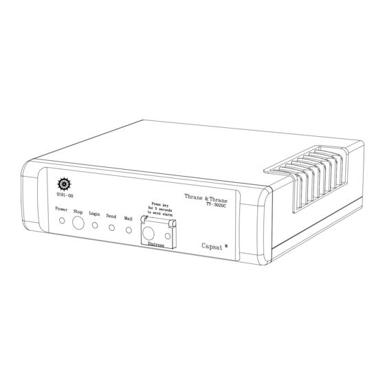
Thrane&Thrane TT-3020C Manuals
Manuals and User Guides for Thrane&Thrane TT-3020C. We have
3
Thrane&Thrane TT-3020C manuals available for free PDF download: Installation Manual, Configuration Manual
Thrane&Thrane TT-3020C Installation Manual (109 pages)
Built-in GPS
Brand:
Thrane&Thrane
| Category:
Transceiver
| Size: 0 MB
Table of Contents
Table of Contents
7
1 Introduction
13
Initial Inspection
13
Figure 1 TT-3020C Maritime Capsat Transceiver
13
Storage
14
Repackaging for Shipment
14
2 Installation - TT-3020C
17
Technical Specifications
17
Table 1 TT-3020C Technical Specifications
18
Compass Safe Distance
19
Table 2 Inmarsat-C Protocol Support
19
Power Requirements
20
Fuse
20
Functional Description
20
On/Off Features
20
Table 3 TT-3020C Power Requirements
20
Front Indicators and Buttons
21
Table 4 TT-3020C Capsat Transceiver ON/OFF Overview
21
Connectors
23
Power Connector
23
Figure 2TT-3020C Capsat Transceiver Rear Panel
23
Table 5 TT-3020C Capsat Transceiver DC Power Connector Pin Assignment
24
DTE Communication Port
25
Table 6 Automatic Baudrate Settings
25
Table 7 TT-3020C X3 Pin Assignment
26
I/O Connector
27
Table 8 TT-3020C X4 Pin Assignment
28
Printer Port
31
Table 9 Printer Port (X5) Pin Assignment
32
Grounding
33
Built-In GPS (Optional)
33
GPS Specifications
34
Mounting Bracket
34
Table 10 GPS Specifications
34
Figure 3 TT-3020C Capsat Transceiver Mounting Plate
35
Figure 4 Front Panel of the TT-3020C Capsat Transceiver with Mounting Bracket
35
3 System Installation
37
Power Requirements
37
Fuses
38
Table 11 Capsat System Component Power Requirements
38
Compass Safe Distance
39
Table 12 Capsat System Fuses
39
Table 13 Compass Safe Distance
40
Antennas
41
TT-3005M Maritime Antenna
41
Figure 5 TT-3005M Maritime Antenna
41
Table 14 TT-3005M Technical Specifications
43
Table 15 TT-3020C Capsat Transceiver Antenna Cable Types
44
Figure 6 TT-3005M 1'' Tube Mounting
45
TT-3005A Maritime Antenna
46
Figure 7 TT-3005A Maritime Antenna
46
Table 16 TT-3005A Technical Specifications
48
Table 17 TT-3020C Capsat Transceiver Antenna Cable Types
49
Figure 8 TT-3005A 1.5'' Tube Mounting
50
TT-3001B Maritime Antenna
51
Figure 9 TT-3001B Opt. 001 Maritime Antenna
51
Table 18 TT-3001B Opt. 001 Technical Specifications
52
Table 19 TT-3020C Capsat Transceiver Antenna Cable Types (N - TNC)
53
Antenna Mounting Considerations
54
Figure 10 TT-3001B-Opt. 001 1.5'' Tube Mounting
54
Figure 11 Inmarsat-C Antenna Mounting
56
Safety Distance for Antenna Units
57
Figure 12 Inmarsat-C Antenna Mounting Near Pole or Funnel
57
Table 20 Radiated Intensity
58
TT-3606E Message Terminal
59
Connectors
59
Figure 13 TT-3606E Message Terminal
59
Figure 14 TT-3606E Rear Connectors
60
Table 21 TT-3606E Power Connector
60
TT-3601E Keyboard
61
Specifications
62
Table 22 TT-3606E Message Terminal Specifications
62
Mounting
63
Figure 15 Mounting Holes for TT-3606E
63
Figure 16 TT-3606E Mounting Bracket
64
TT-3680B Power Supply
65
Mounting
65
Figure 17 TT-3680B - 200W Power Supply
65
Figure 18 Mounting Holes for TT-3680B
66
TT-3608A Hard Copy Printer
67
Figure 19 TT-3608A Hard Copy Printer
67
Figure 20 TT-3608A Paper Roll Stand
68
Mounting Plate
68
Roll Paper Stand
68
Figure 21 Mounting Holes for TT-3608A
70
Mounting
70
TT-3608G Printer Unit
71
Figure 22 TT-3608G Remote Printer Unit
71
Configuration
72
Table 23 TT-3608G DIP Switch Settings
73
Connectors
74
Installation
74
Table 24 TT-3608G Power Connector
74
Cable
75
Table 25 TT-3608G I/O Connector
75
Specifications
77
Table 26 TT-3608G Technical Specifications
77
TT-3042C Remote Alarm/Distress Box (Optional)
78
Figure 23 TT-3042C Remote Alarm/Distress Box
78
Table 27 TT-3042C and Satellite Communication Unit Inter-Connection
79
Table 28 TT-3042C Technical Specifications
80
Figure 24 TT-3042C Outline Drawing
81
Mounting
81
Figure 25 TT-3042C Outline Drawing with Console Bracket
82
Figure 26 TT-3042C Mounting Stencil
83
TT-3042D Remote Alarm / Printer Unit
84
Figure 27 TT-3042D Remote Alarm Distress Box / Local Printer
84
Configuration
85
Table 29 TT-3042D DIP Switch Settings
87
Connectors
88
Installation
88
Table 30 TT-3042D Power Connector
88
Cable
89
Table 31 TT-3042D I/O Connector
89
Specifications
91
Table 32 TT-3042D Technical Specifications
91
Distress Button Test
92
3.10.1 TT-3020C Transceiver
92
3.10.2 TT-3042C Remote Alarm/Distress Box
93
3.10.3 TT-3042D Remote Alarm Distress Box
93
General Interconnect Information
94
Figure 28 Interconnection Diagram
95
4 System Generation
97
Terminal Mode
97
TT-3606E Message Terminal
97
Computerised Equipment/Handheld Terminals
97
Initialise System Parameters
98
Entering Your Mobile Number
98
Altering Baudrate and Protocol Settings
99
Antenna Voltage Settings
100
Table 33 Antenna Voltage Configuration
100
5 Commissioning
103
Introduction
103
The First Login
103
Link Test
104
Details of a Link Test
104
6 Index
107
Advertisement
Thrane&Thrane TT-3020C Configuration Manual (96 pages)
VMS Capsat Transceiver
Brand:
Thrane&Thrane
| Category:
Transceiver
| Size: 0 MB
Table of Contents
Table of Contents
7
1 Introduction
15
An Introduction to Terms
15
Figure 1 System Overview
16
Figure 2 LES, DNID and Member Number
16
Short Feature Description
17
Restriction to the SOLAS Fishery
19
2 LES Interface
21
DNID Common Format
21
API Header Format
22
Figure 3 API Header of DNID File
22
First Part of Positioning Report
23
Figure 4 First Part of Position Report
23
Second Part of Positioning Report
25
Figure 5 Second Part of Position Report
25
3 Initial Setup of Transceiver
27
TT-3020C SOLAS Transceiver
27
Making a SOLAS Fishery Transceiver
27
Figure 6 TT-3020C Maritime Capsat Transceiver
27
Ocean Registration
28
TT-3028CM Dual Mode Fishery Transceiver
29
Making a SOLAS Fishery Transceiver
29
Figure 7 TT-3020C Maritime Capsat Transceiver
29
Ocean Registration
30
TT-3022D Fishery Transceiver
31
Ocean Registration
31
Figure 8TT-3022D Fishery Capsat Transceiver
31
TT-3022C Landmobile Transceiver
32
Making a Landmobile Vehicle Surveillance Transceiver
32
Figure 9 TT-3022C Land Mobile Transceiver
32
Ocean Registration
33
4 Transceiver Configuration
35
Configuring the VMS Behaviour
35
Quit
36
Figure 10 Fishery Configuration Menu (Fi)
36
Set All Values to Default
37
Date and Time Format
37
Antenna Blocked/Disconnected Followed by Normal Position Report
40
Retransmit Fail Reports
40
Figure 12 Antenna Blocked/Disconnected Reports
40
Blocked GPS Detection
41
Long to Short Report Interval Change
41
Nice Power down Support
42
Figure 13 Automatic Change of Reporting Interval
42
Disable Send LED on Position Report TX
45
Stop Button Initiates Position Report
45
Figure 14 In-Port Button
46
Disable Position Report Infos
47
Password on Da-Command
47
Only 1 Packet Per Position Report
48
Mask out Speed and Course
48
Disable GPS First Fix Beep
49
A' in Provider Downloads VMS DNID
49
Use VMS DNID for Special Reports
50
Hide Remote Connections
51
Keep Inactive Connections
52
MEM Code Translation Table
52
Number of Positions in Storage Queue
53
Table 3 Default Macro Encoded Messages
53
Position Report Packet 2 - Bit Mask
54
Reporting Intervals
55
Reporting Interval Change Distance
56
VMS DNID and VMS LES
56
Number of Active DNID in Transceiver
57
Password Protection
57
Table 4 Password Protected Commands
59
Automatic Ocean Region Shift
60
Reduced Transmission Mode
61
Figure 15 Reduced Transmission Mode
62
Figure 17 Position, Speed and Course Shown Graphically
63
Figure 18 Vessel/Vehicle Track
63
Figure 19 Reports from MES in Reduced Mode
63
Sleep Mode
64
Figure 20 Radius Used to Check for Reduced Transmission
64
Setting up Sleep Mode Operation
65
Table 5 Sleep Mode Command
66
Surveillance Zones
67
Figure 21 Zone Example
68
Table 6 Possible Zone Shapes
68
Setting up Surveillance Zones
69
5 Remote Configuration of the Transceiver Via Poll
71
VMS Configuration
71
Table 7 T&T Remote Configuration
71
Table 8 T&T Poll Command List
73
Figure 22 Poll Command Checksum Calculation
74
Fishery Configuration (FI Command) Poll
75
Zone Configuration Poll
77
Table 9 Connection between Entry Number and Parameters
77
Table 10 Connection between Zone Type and Zone Data
78
VMS Set-Up Acknowledgement
79
Fishery Set-Up Poll Example
82
Figure 23 Example of Remote Poll Configuration
83
VMS Connection for Multiple Ocean Regions
84
Figure 24 Open Connection Poll
85
Table 11 Positive Open Connection Acknowledgement
86
Table 12 Negative Open Connection Acknowledgement
86
Sleep Mode Set-Up Poll
87
Figure 25Sleep Mode Set-Up Poll
87
Reduced Transmission Mode Set-Up Poll
88
Figure 26 Sleep Mode Acknowledge Report
88
Figure 27 Reduced Mode Set-Up Poll
88
Figure 28 Reduced Mode Acknowledge Report
89
6 Development Tips
91
7 Index
93
Thrane&Thrane TT-3020C Installation Manual (20 pages)
Brand:
Thrane&Thrane
| Category:
Transceiver
| Size: 0 MB
Table of Contents
Table of Contents
5
Introduction
11
Initial Inspection
11
Storage
12
Repackaging for Shipment
12
Installation - TT-3020C
15
Technical Specifications
15
Compass Safe Distance
17
Power Requirements
18
Fuse
18
Functional Description
18
On/Off Features
18
Front Indicators and Buttons
19
Advertisement
Advertisement
Related Products
Thrane&Thrane TT-3020B
Thrane&Thrane tt-3022d
Thrane & Thrane TT-3028CM
Thrane&Thrane TT-3022C
Thrane&Thrane TT-3026L easyTrack
Thrane&Thrane TT-3734A
Thrane&Thrane TT-5053A
Thrane&Thrane TT-3055B
Thrane&Thrane TT-3057A
Thrane&Thrane TT-3080A
Thrane&Thrane Categories
Antenna
Touch terminals
Transceiver
Marine GPS System
Marine Equipment
More Thrane&Thrane Manuals
Login
Sign In
OR
Sign in with Facebook
Sign in with Google
Upload manual
Upload from disk
Upload from URL